
Abstract
This paper investigates research on the dynamic mechanical and energy consumption models during the polyethylene tube retrieval for a self-propelled hard hose traveler. Moreover, the drive parameter design methodology of a traveler is refined to address the irrigation challenges faced by existing sprinklers in sloping fields and fragmented farmland. First, the sprinkler’s electric-drive carrier parameters are designed based on established mechanical theory models of the polyethylene tube deployment. The carrier employs two planetary reduction gearboxes with a transmission ratio of 40 and six batteries with a voltage of 12 V and a capacity of 200 A h. Secondly, the dynamic changes in tensile force and energy consumption are studied by establishing mechanical and energy consumption models for retrieving polyethylene tubes. Then, the drive parameters for the reel truck are designed. The tensile force required for its rotation increases because the polyethylene tube winds longer onto the reel. Moreover, the tensile force and total energy consumption required for retrieving the polyethylene tube decrease. The force required for reel no-load rotation is 49.98 N. When the friction coefficient between the polyethylene tube and soil is 1.0, the tensile force and energy consumption required for sliding are maximized, to 2356.70 N and 52.06 × 10⁻³ kW h, respectively. The reel truck selects a reduction gearbox with a transmission ratio of 25 and an efficiency of 85%, along with a three-phase asynchronous motor with a power of 750 W, a speed of 1400 r min−1, and a voltage of 220 V. This research will enable in-depth analysis of mechanical and energy consumption characteristics across different operational stages of the polyethylene tube, facilitate structural optimization, and provide technical support for irrigation in sloped and fragmented farmlands.
Keywords
Introduction
Irrigated agriculture has always been the cornerstone for ensuring national food security. 1 Water-saving irrigation equipment is evolving toward automated control and strong adaptability due to the development of the economy and society.2–4 Due to the high proportion of sloping land, the fragmentation of basic farmland in China, and poor regularization,5,6 the applicability of existing mature sprinkler irrigation machines is insufficient to meet the needs of large-scale farming. The traditional hard hose traveler is a type of sprinkler that continuously moves and operates through a water turbine drive, and it is relatively suitable for use in plain farmland in China.2,7–10 However, its applicability in sloping and fragmented farmland, as well as the level of automatic control, must be enhanced.
This paper introduces a self-propelled hard hose traveler to address the irrigation issues associated with the aforementioned types and patches of farmland. The traveler boasts advantages such as cross-country climbing ability and maneuverability, primarily achieving multi-directional or continuous slope irrigation using an electric-driven carrier to mount the sprinkler. The hose traveler also incorporates another drive device (electric motor) on the hose reel cart to retrieve the waterless polyethylene tube, 11 enhancing the applicability of the traditional hard hose traveler in farmland. Additionally, the electric-driven carrier can serve as a mobile platform for fruit and vegetable management,12,13 harvesting,14,15 and transportation16,17 within greenhouses, enabling composite functional applications of the sprinkler irrigation machine and reducing the overall investment cost for multiple types of agricultural machinery. Therefore, designing the driving parameters for the self-propelled hard-hose traveler is particularly crucial.
The driving parameters of this sprinkler irrigation machine are influenced by the mechanical changes in the rotation of the reel and the sliding of the polyethylene tube. There is limited literature on the mechanical changes in reel rotation and polyethylene tube sliding, with research primarily focusing on reel torque and polyethylene tube sliding energy consumption. Previous research has been conducted on the driving energy consumption, 18 irrigation energy consumption, 19 and tube head loss 20 of traditional hard hose traveler. For example, Oakes and Rochester 21 investigated the distribution of various energy consumptions in the total energy consumption, Biolan et al. 22 proposed a computational model for optimizing the performance of water turbines, and Rochester and Flood 23 presented an expression for the additional head loss caused by tube bends. However, none of these studies addressed the reel torque and the energy consumption associated with the sliding of the polyethylene tube. Li 24 analyzed the polyethylene tube retrieval status of the traditional hard hose traveler through calculation methods. The author derived the torque variation curve with load (i.e. the length of the polyethylene tube). Wang 25 and Xu 26 investigated the power loss and transmission efficiency of the JP50-180 reel through load simulation tests. The authors concluded that load mass and retrieval speed are the main factors affecting power consumption during reel retrieval. Zhang et al. 27 conducted research through theoretical calculations. The author pointed out that the energy consumption of reel rotation is influenced by the length of the polyethylene tube and the friction coefficient between mechanical components. Ge 28 established an energy consumption calculation model for the sprinkler cart, polyethylene tube, and reel based on the traditional hard hose traveler. The author explored the impact of the polyethylene tube length and diameter on energy consumption but did not combine this with experimental analysis. The above literature has explored the mechanics, torque, and energy consumption of the traditional hard hose traveler operation mode. However, the same investigations primarily focus on retracting the polyethylene tube onto the reel, without separately investigating the mechanics and energy consumption of the reel rotation and polyethylene tube sliding. Moreover, the above literature does not consider the impact of soil surface roughness on the friction between the polyethylene tube and the soil. Lastly, the above investigations lack the design of relevant driving parameters. Xu et al. 29 developed a polyethylene tube’s mechanical and energy consumption calculation model using a self-propelled hard hose traveler. Furthermore, the author selected two servo motors with a voltage of AC 380 V and a power of 5500 W for the electric-driven carrier based on extreme operating conditions of climbing a 30° slope, a speed of 5000 m h−1, no turning, and overcoming a tensile force of 6500 N. However, the author did not select the parameters for the reduction gearbox and battery of the electric-driven carrier.
Based on the research by Xu et al., 29 this paper will design the parameters for the gearbox and battery of the electric drive carrier. Additionally, the friction coefficient between the polyethylene tube and soil ranges from 0.3 to 1.0 (considering comprehensive factors such as ground slope) provided in “Traveler irrigation machines-Part 1: Operational Characteristics and Laboratory and Field Test Methods.” 30 Therefore, this paper will establish and analyze the mechanical and energy consumption models for retrieving the polyethylene tube of the self-propelled hard hose traveler. Furthermore, the drive parameters (for Motor I and Gearbox I) on the reel cart will be designed to guide the autonomous movement of the sprinkler irrigation machine.
This paper establishes an energy consumption model for the polyethylene tube retrieval phase of the self-propelled hard hose traveler by integrating the dynamic process of the polyethylene tube deployment, refining the driving parameters design methodology. This research will enable in-depth analysis of mechanical and energy consumption characteristics across different operational stages of the polyethylene tube, facilitate structural optimization, and reduce manufacturing and operational costs. The findings will provide technical support for irrigation in sloped and fragmented farmlands while offering innovative approaches for the development of water-saving irrigation equipment.
The structure of the self-propelled hard hose traveler
The structure and working principle of the sprinkler irrigation machine
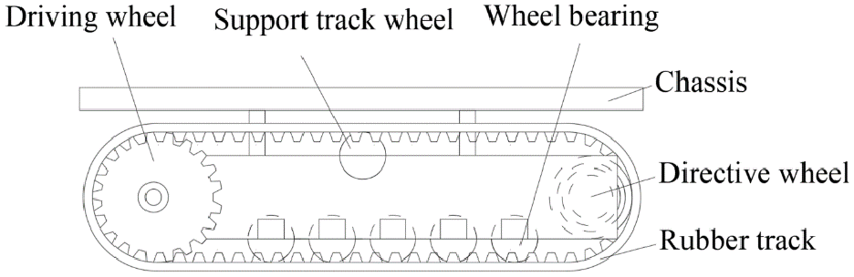
As shown in Figure 1, the self-propelled hard hose traveler mainly comprises components such as the reel cart, electric-drive carrier, impact sprinkler, motor I, and gearbox I. The reel cart can deploy, store, and retrieve the polyethylene tube. The electric-drive carrier features maneuverability, flexibility in movement, and the ability to carry an impact sprinkler, primarily serving to change the irrigation position, deploy a polyethylene tube, and provide guidance. Based on the JP50-150 traditional hard hose traveler, this irrigation machine adopts a fixed flow rate design (the maximum value among the recommended economic flow velocities for pipelines) and achieves different irrigation volumes by altering the movement speed of the impact sprinkler. The machine’s polyethylene tube is 180 m in length.

The structure of the self-propelled hard hose traveler.
Figure 2 depicts the prototype of the self-propelled hard hose traveler, supplied with water through a multi-stage pump. The total valve and flowmeter control and display the flow rate, respectively. During sprinkler irrigation operations, the electric-drive carrier is activated via a remote terminal on an application to move forward and drag the polyethylene tube to slide ahead (with the electric-drive carrier moving away from the reel cart). The impact sprinkler rotates to spray water while the slider and tube rack slide along the guide rod toward a more precise position on the reel cart for the tube deployment. After the sprinkler irrigation operation, the electric-drive carrier returns to the water source point. Then, Motor I drives the reel to rotate and retrieve the polyethylene tube (assuming there is no water in the polyethylene tube by default). The slider and tube rack slide along the guide rod toward a more precise position on the reel cart for tube retrieval. The self-propelled hard hose traveler is transferred to the next irrigation area after completing the abovementioned tasks.

The prototype of the self-propelled hard hose traveler.
The structure and working principle of the electric-drive carrier
Figures 3 to 5 show that the electric-drive carrier mainly comprises Motor II and Gearbox II, an application remote terminal, a controller, a driver, a battery, a 4G antenna, rubber tracks, and other components. The carrier has dimensions of 2.3 m in length, 1.1 m in width, and 0.6 m in height and features two modes: irrigation and transfer. The irrigation mode operates more slowly for sprinkler irrigation mobility, while the transfer mode is faster for rapid relocation. The electric-drive carrier moves in a straight line through the opposite rotation of the two Motor IIs. The carrier achieves multi-directional turning by rotating the two Motor IIs in the same direction and adjusts walking speeds by regulating the rotational speed of the Motor IIs. Lastly, the carrier implements braking through cut-off commands and receives and sends commands via the 4G antenna.
Part of the structure of the electric-drive carrier.

Physical model and component diagrams of the electric-drive carrier.

An application remote terminal.
The structure of the reel cart
As shown in Figures 6 and 7, the structure of the reel cart mainly comprises components such as the reel, polyethylene tube, chain wheel, guide rod, slider, and tube rack. The connection method between Gearbox I and the Input sprocket is shown in Figure 7. The mechanical transmission sequence of the components is as follows: Motor I, Gearbox I, and the chain connecting to the chain wheel. The guide rod, slider, and tube rack ensure the polyethylene tube is neatly arranged. Motor I is equipped with Gearbox I to prevent overheating and burnout due to low-frequency operation while addressing the issue of insufficient torque output resulting from low efficiency. Since power is available at the multi-stage pump, this paper does not discuss the provision of auxiliary batteries for the reel cart.

The structure of the reel cart.

Transmission mode of Motor I, Gearbox I, and Reel Cart.
Theoretical model of mechanics and energy consumption of polyethylene tube
The driving parameters of the electric-drive carrier and the reel cart are constrained by the tensile forces during deployment (polyethylene tube filled with water) and retrieval (polyethylene tube empty) of the polyethylene tube. Since the mechanical and energy consumption models for deploying the polyethylene tube have already been discussed, 29 the following section will establish theoretical models for the mechanics and energy consumption of retrieving the polyethylene tube.
The retrieval of a polyethylene tube can be divided into two dynamic stages: reel rotation and polyethylene tube sliding. During this process, the load on the reel continues to increase. At the same time, the sliding length of the polyethylene tube on the ground decreases. The tensile force required for retrieving the polyethylene tube is the total tensile force. The dynamic tensile forces required for the reel rotation or polyethylene tube sliding (from the beginning to the end of the operation) are referred to as the required tensile force for reel rotation or polyethylene tube sliding, respectively. The mechanical and energy consumption models for retrieving the polyethylene tube are constructed based on the winding and stacking pattern of the polyethylene tube on the reel, as specifically illustrated in Figure 8. The distance from the centerline of the reel to the dot on the cross-section of the polyethylene tube is the winding radius. The layers of polyethylene tube wound on the reel are named sequentially from the innermost to the outermost. Lastly, the dots on three tangent polyethylene tubes form an equilateral triangle.
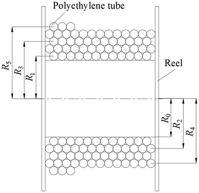
The winding and stacking method of the polyethylene tube on the reel.
Five assumptions are made based on the above models:
(1) The reel is considered a cylindrical rigid body.
(2) The fluctuation in tensile force required for reel rotation is neglected during the transition between layers of polyethylene tube on the reel. Multiple verification tests on tension fluctuation when switching the polyethylene tube layer counts have demonstrated that the fluctuation in tension values is less than 10 N, accounting for less than 1.3% of the total tensile force.
(3) The friction coefficients during reel rotation and polyethylene tube sliding are assumed to be constant under the same operating conditions. According to the tension test verification of the reel rotation, the variation value of the tension is approximately 6 N, accounting for 1.8% of the reel rotation tension. On the other hand, according to the tension test verification of the polyethylene tube translational motion, the variation value of the tension is approximately 15 N, accounting for 1.2% of the tension required for the polyethylene tube sliding.
(4) The suspended length of the polyethylene tube between the reel and the ground is ignored. The suspended length of the polyethylene tube is measured as approximately 1.2 m, accounting for 0.7% of the polyethylene tube’s total length.
(5) The liquid flow within the polyethylene tube does not impact the tensile force and energy consumption required for retrieving the polyethylene tube. According to the multiple pressure water supply tests, the influence range of reel vibration on the total tension is between 10 and 15 N, accounting for less than 1.9% of the total tensile force.
Given that the above assumptions hold true, the model will be mainly divided into the following three steps.
(1) Determine the tensile force F1 required for the reel to rotate, as shown in equation (1).

where F1 is the tensile force required for the reel to rotate, N; μ1 is the friction coefficient between mechanical components during reel rotation, taken as 0.05 in this paper; m0 is the unloaded weight of the reel, kg; ΔmPE is the mass per unit length of the polyethylene tube when it is empty, kg m−1; and x is the length of the polyethylene tube wound on the reel, m.
(2) The tensile force F2 required for the polyethylene tube to slide is determined, as shown in equation (2). National Standard GB/T 21400.1-2008 27 indicates that the polyethylene tube and soil friction coefficient ranges from 0.3 to 1.0, encompassing comprehensive field factors such as soil moisture content and ground slope.

where F2 is the tensile force required for the polyethylene tube to slide uniformly on the ground, N; S is the total length of the polyethylene tube in the reel cart, m; and μ2 is the friction coefficient between the polyethylene tube and the soil.
(3) The total tensile force F, torque T n , and energy consumption E for retrieving the polyethylene tube are determined. The winding radius of the nth layer of the polyethylene tube can be obtained using the reel’s no-load radius and the polyethylene tube’s diameter, as shown in equation (3). The calculation method for the reel rotation angle when retrieving the nth layer of the polyethylene tube is shown in equation (4). The calculation methods for the total tensile force, torque, and energy consumption are presented in equations (5)–(7), respectively.


where R n is the winding radius of the nth layer of the polyethylene tube, m; n is a positive integer; d is the outer diameter of the polyethylene tube, m; i1 is the starting layer number of the polyethylene tube in the summation formula; j n −1 is the total number of turns of the (n−1)th layer of polyethylene tube wound on the reel; L n is the winding circumference of each turn of the nth layer of the polyethylene tube, m; F is the total tensile force required to retrieve the polyethylene tube, N; α n is the rotation angle of the nth layer of the polyethylene tube, rad; T n is the torque required to retrieve the polyethylene tube, N m; E is the total energy consumption for retrieving the polyethylene tube, kW h.
Mechanical test measurement methods and model validation
Since the construction methods for the mechanical theoretical models of deploying and retrieving the polyethylene tube are similar, this paper will utilize the mechanical tests of deploying the polyethylene tube to validate the mechanical model for retrieving the polyethylene tube.
Measurement methods for mechanical tests
As shown in Figure 9, the polyethylene tube is pulled out straight, and the tensile force is measured by a tensile tester. Every 10 m is taken as a tensile force measurement point, and multiple measurements are taken at each point to obtain an average value. The measuring range of the tensile tester is from 0.1 to 10 kN, with an accuracy of 0.1 N. A section of water-free polyethylene tube is selected, and its weight is measured as 1.336 kg m2 using the weighing method. The test site is located at the Huantai Lizhong Agricultural Machinery Cooperative in Zibo City, Shandong Province, China, which has a relatively flat terrain with a slope within ±1° (defaulted to 0° in this paper). Once the polyethylene tube is filled with water using a pump, the main valve is closed, and the water outlet is sealed.

Tensile test process for dragging a polyethylene tube filled with water.
In this paper, the stability of the friction coefficient between the polyethylene tube and the soil is maintained by leveling the field roads, providing a basis for designing driving parameters. Locally uneven field roads are leveled. The road’s concave and convex areas are marked, filled, and compacted, allowing the moving machinery to travel over it. Lastly, the chain measurement method measures soil surface evenness. 31 The selected chain length is 4 m. Multiple measurement points are chosen along a level field road, each measured and averaged three times. The calculation method for soil surface evenness is shown in equation (8), and the soil surface evenness after leveling the road is 99.6%.

where C is the soil surface evenness, %; H1 is the length of the chain, m; and H2 is the length of the chain measured with a tape measure, m.
Experimental validation of the mechanical model
This paper calculates the weight of the reel fully loaded with 180 m of polyethylene tube to be 548.58 kg using the data of the reel’s self-weight of 102 kg and the weight of the dry polyethylene tube at 1.336 kg m−1. The theoretical and experimental values for the tensile force required to rotate the fully loaded reel are 276.6 and 285.02 N, respectively, with a deviation rate of 2.25% between the tensile force values.
The tensile force required for the polyethylene tube to slide is minimal under conditions such as a ground slope of 0° and soil flatness of 99.6%. Under this operating condition, the experimental value of the tensile force for sliding a 180 m polyethylene tube filled with water is 1358.3 N. According to national standards, the minimum friction coefficient between the polyethylene tube and soil is 0.3. Thus, the theoretical value of the tensile force for sliding a 180 m polyethylene tube filled with water is 1258.3 N. The deviation rate between the theoretical and experimental values of the tensile force is 8.3%.
The deviation rate between the above-mentioned theoretical and the experimental tensile force values is approximately 5%. Therefore, this paper considers that a mechanical theoretical model for recycling polyethylene tubes highly reliable.
Mechanical and energy consumption analysis of polyethylene tube
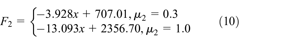
The tensile force required for the reel to rotate for the weight of 240.48 kg in a 180 m length of dry polyethylene tube is given by equation (9), while the force required for the reel to rotate unloaded is 49.98 N in Table 1. As the load on the reel increases, the force required for rotation gradually increases. According to equation (2), equation (10) can be derived for the tensile force needed for the polyethylene tube to slide when the friction coefficient between the polyethylene tube and soil is 0.3 and 1.0. As the polyethylene tube wrapped on the reel becomes longer, the tensile force required for the polyethylene tube to slide decreases; the maximum tensile forces required for sliding are 707.01 and 2356.70 N in Table 1. Equation (11) is the sum of equations (9) and (10), representing the tensile force required to retrieve the polyethylene tube. According to equation (11), the tensile force required to retrieve the polyethylene tube decreases as the reel load increases. Therefore, the maximum tensile force occurs when the polyethylene tube is unwound over 180 m. The maximum tensile forces required for retrieving the polyethylene tube are 755.99 and 2406.68 N, as detailed in Table 1. The dynamic torque during the retrieval of the polyethylene tube by the reel is shown in Figure 10 and Table 1. When the friction coefficient between the polyethylene tube and soil is 0.3 and 1.0, the maximum torques are 362.12 and 1152.80 N m, respectively, while the minimum torques are 113.05 and 109.47 N m in Table 1, respectively.


Tensile force and torque required for retrieving polyethylene tube using the reel.

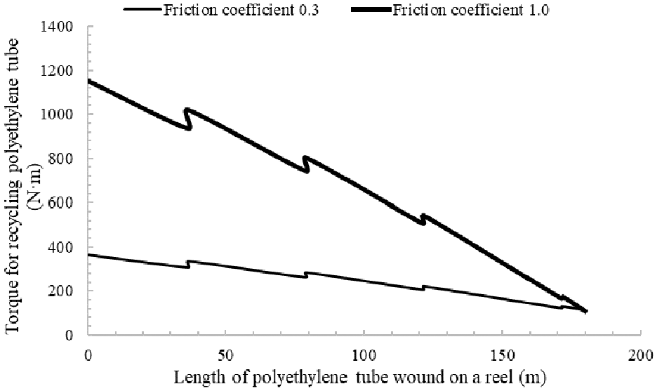
Dynamic torque during the recycling of polyethylene tube using a reel.
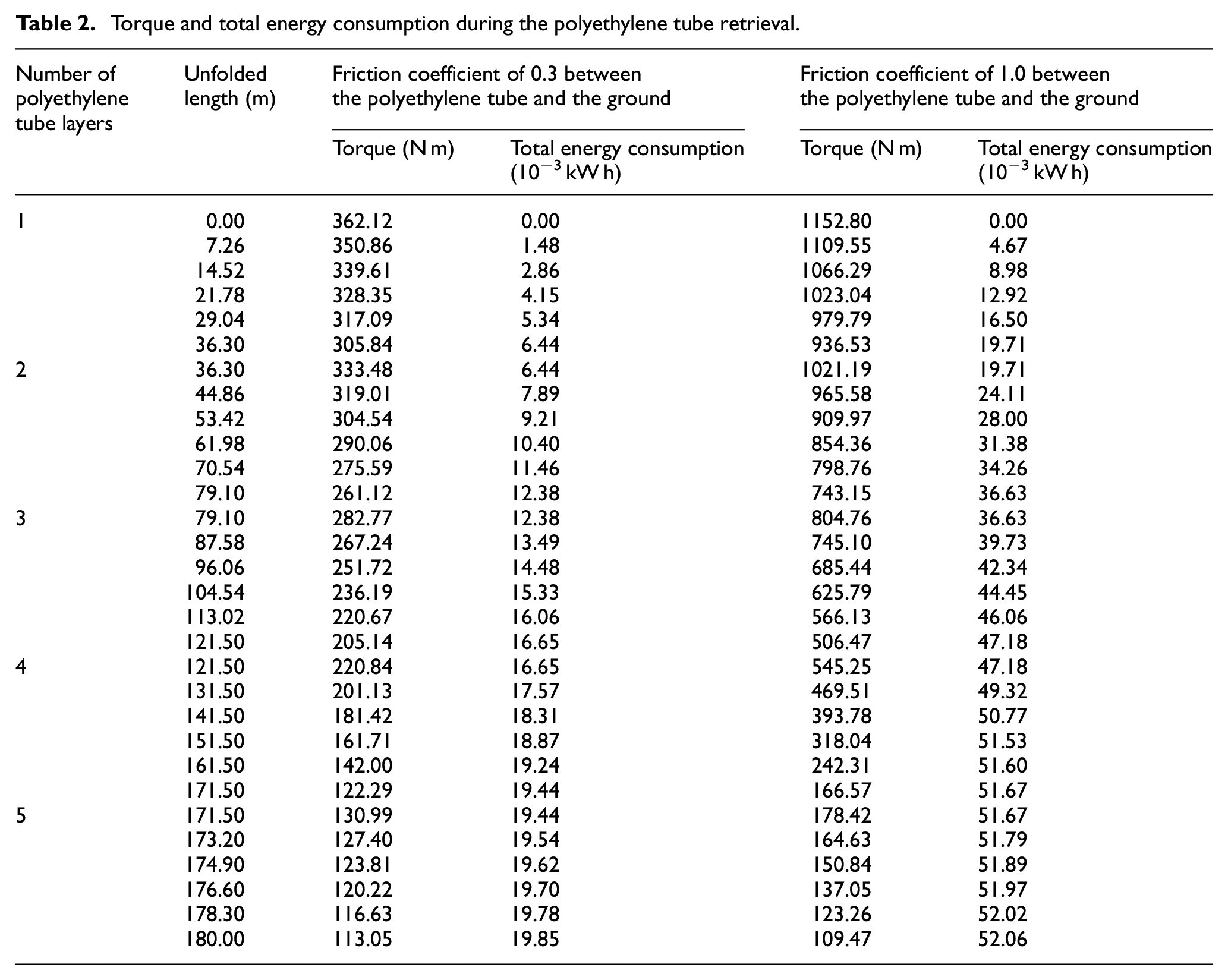
When the friction coefficients between the polyethylene tube and soil are 0.3 and 1.0 in Table 2, the total energy consumption for fully retrieving the polyethylene tube is 19.85 × 10⁻³ and 52.06 × 10⁻³ kW h, respectively. The variation process of total energy consumption is illustrated in Figure 11. According to Table 2, the two curves are divided into five segments, with slight fluctuations at the nodes during the layer-changing process of the reel. The two curves are fitted with quadratic functions, yielding coefficients of 0.9998 and 0.9997, indicating good fitting results and allowing the use of equation (12) for representation. During polyethylene tube retrieval, the variation in total energy consumption gradually decreases with an increase in the length of the polyethylene tube wound on the reel. This phenomenon can be attributed to the large proportion of sliding energy consumption of the polyethylene tube in the total energy consumption.

Torque and total energy consumption during the polyethylene tube retrieval.
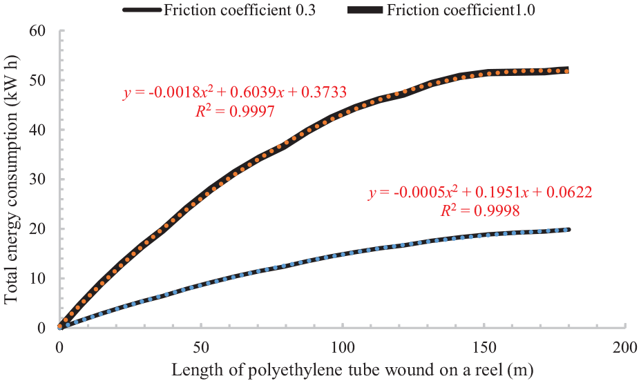
Total energy consumption during the polyethylene tube retrieval.
Designing the driving parameters
The driving parameters for the electric-drive carrier and the reel cart are based on the mechanical theoretical models for unfolding and retrieving the polyethylene tube, respectively.
Driving parameters of the electric-drive carrier
Selection of gearbox II
The design and selection results in the literature 29 indicate a rated speed of 2000 r min2 for the servo motor, a drive wheel diameter of 291 mm for the rubber track chassis, and a maximum speed of 5000 m 2 for the electric-drive carrier. Equation (13) from the literature 32 is used to obtain the transmission ratio of gearbox II, that is, i ≤ 43.9. This paper selects a planetary gearbox with a transmission ratio of 40 and an efficiency of 97% to improve energy conversion efficiency.

where n e max is the rated speed of the servo motor, r min2; vmax is the maximum speed of the electric-drive carrier, km h2; i is the transmission ratio of gearbox II; and r1 is the radius of the drive wheel of the rubber crawler chassis, m.
Battery capacity selection
Since the maximum discharge current of the battery for the electric drive platform must not exceed 300 A, the operating voltage Uess should satisfy the relationship shown in equation (14) (assuming a discharge current of 300 A). The maximum power during the operation of the electric-drive carrier is based on the limit power for prolonged operation, which is taken as 4 kW. The calculation method for the battery capacity is shown in equation (15):

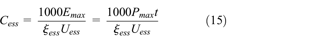
where Pmax is the limit power for prolonged operation of the electric-drive carrier, kW; Emax is the actual energy consumed by the battery, kW h; Uess is the operating voltage of the battery, V; ξess is the depth of discharge, typically 80%; Cess is the capacity of the battery, A h; and t is the operating time of the electric-drive carrier at its limit power for prolonged operation (taken as 1 h).
Based on the analysis of actual working conditions, it is determined that Uess ≥ 13.33 V. In this paper, Uess is selected as 72 V, and the calculated value of Cess is approximately 64.4 A h. A battery capacity of 200 A h is selected to provide the electric drive carrier with stronger endurance.
In summary, the electric-drive carrier comprises two planetary gearboxes with a transmission ratio of 40 each and six batteries with a voltage of 12 V and a capacity of 200 A h each. A controller converts the direct current (DC) 72 V from the batteries to alternating current (AC) 380 V to power the servo motor.
Driving parameters of the reel cart
The driving parameters of the reel cart are closely related to the operating time of the self-propelled hard hose traveler. Increasing the retrieval speed of the polyethylene tube can reduce the operating time of the self-propelled hard hose traveler. The maximum linear speed for unwinding the polyethylene tube of a traditional hard hose traveler is 5 km h−1 (the speed at which the tractor pulls out the polyethylene tube). 33 Furthermore, the maximum winding radius of the JP50-180 model is 4.1 m r−1. 29 Therefore, the maximum unwinding reel rotation speed is 20.3 r min−1. This paper sets the reel rotation speed at 4.5 r min−1 to improve the stability and safety factor of the reel cart.
The data for the reel, input sprocket, and the polyethylene tube of the self-propelled hard hose traveler are shown in Table 3. Since the reel sprocket has 200 teeth and the input sprocket has 18 teeth, the rotational speed of the input sprocket should be 50 r min−1 according to equation (15). Hence, equation (16) can be derived based on equation (15) and the relationship between the speed, power, and torque of Motor I. When the friction coefficient between the polyethylene tube and the soil is 0.3 and 1.0, the maximum torque of the input sprocket is 32.59 and 103.75 N m, respectively.

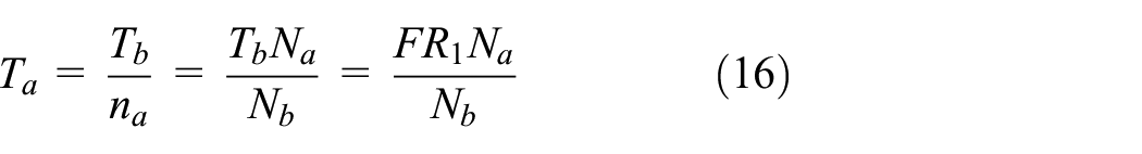

where Pmotor is the expected power of Motor I, W; T a is the torque of the input sprocket, N m; T b is the torque of the winding reel, which is the maximum value of T n , N m; n a is the output rotational speed of Gearbox I, min−1; n b is the rotational speed of the winding reel, min−1, which is taken as 4.5 min−1; η1 is the mechanical transmission loss of Chain I and the input sprocket, which is taken as 0.9; η2 is the transmission efficiency of Gearbox I, which is taken as 0.85; N a = 18 and N b = 200 are the number of teeth on the input sprocket and the winding chain wheel I, respectively.
Data for the reel, input sprocket, and polyethylene tube.

Motor I, operating at low speeds, faces low efficiency and overheating issues. Therefore, this paper proposes matching Motor I with Gearbox I, which has a gear ratio of 25 and an efficiency of 85%. According to equation (17), once Motor I reaches the torque mentioned above and the power reserve coefficient is set to 1.2, the power required for Motor I is 267.65 and 852.08 W.
Since the overload capacity of Motor I can be utilized to overcome extreme operating conditions (i.e. when the friction coefficient between the polyethylene tube and the soil is 1.0), this paper selects a three-phase asynchronous motor with a power of 750 W, a rotational speed of 1400 min−1, and a voltage of 220 V to reduce the initial investment cost.
Conclusions
This paper has designed the parameters for the gearbox and battery of the electric-drive carrier. Additionally, by establishing and analyzing the mechanical and energy consumption models for retrieving the polyethylene tube of the self-propelled hard hose traveler, the driving parameters on the reel cart (specifically for Motor I and Gearbox I) have been designed to guide the autonomous movement of the sprinkler irrigation machine.
(1) A theoretical model for the mechanics and energy consumption of recycling the polyethylene tube was established in this paper. The deviation rate between the theoretical and experimental values for the tensile force required for reel rotation is 2.25%, and the deviation rate for the tensile force required for the polyethylene tube sliding is 8.3%. The force required for reel rotation gradually increases with reel load. As the length of the polyethylene tube wound on the reel increases, the tensile force required for the polyethylene tube sliding decreases. The tensile force required for recycling the polyethylene tube decreases with increased reel load. The change in total energy consumption gradually decreases with an increase in the length of the polyethylene tube wound on the reel while recycling the polyethylene tube.
(2) The force required for rotating the reel under no-load conditions is 49.98 N. When the friction coefficients between the polyethylene tube and the soil are 0.3 and 1.0, the maximum tensile forces required for the polyethylene tube sliding are 707.0 1 and 2356.70 N, respectively. The maximum torques required for the reel to recycle the polyethylene tube are 362.12 and 1152.80 N m, respectively, with the total energy consumptions being 19.85 × 10⁻³ and 52.06 × 10⁻³ kW h, respectively.
(3) The electric-drive carrier is equipped with two planetary reduction gearboxes with a transmission ratio of 40 and six batteries with a voltage of 12 V and a capacity of 200 A h. The reel cart is equipped with a reduction gearbox with a transmission ratio of 25 and an efficiency of 85%, and a three-phase asynchronous motor with a power of 750 W, a rotational speed of 1400 r min−1, and a voltage of 220 V.
Currently, the performance of the self-propelled hard hose traveler is still under research. In future studies, a comprehensive evaluation system will be established for these irrigators, using parameters such as sprinkler model, nozzle diameter, sprinkler rotation angle, and adjacent path spacing, along with evaluation indicators including average application depth, Christiansen Uniformity Coefficient (CU value), total energy consumption, and irrigation capacity. The CU value was calculated based on the average application depth, with a certain correlation between them. Within the same field plot, total energy consumption and irrigation capacity are influenced by the adjacent path spacing. Lastly, a certain correlation between these two factors can also be observed.
Future research will adopt a comprehensive evaluation method in response to the issue of intercorrelation among multiple indicators of the self-propelled hard hose traveler. Multiple indicators will be transformed into a smaller number of comprehensive indicators by applying the concept of dimensionality reduction, enabling multivariate statistical analysis. This approach can eliminate the correlated effects among evaluation indicators, reduce the workload of indicator selection, and minimize the risk of omitting key indicators that could affect the evaluation results. This research can be improved, and optimal parameter configuration schemes can be derived to guide their application in agricultural fields.
Footnotes
Handling Editor: Shuangxi Xie
Funding
The author(s) disclosed receipt of the following financial support for the research, authorship, and/or publication of this article: This research was supported by the following grants: The Natural Science Foundation of the Jiangsu Higher Education Institutions (24KJB210020); the Key Laboratory of Fluid and Power Machinery (Xihua University), Ministry of Education (LTDL-2024015); Suzhou Vocational University (202305000003, KY202304003).
Declaration of conflicting interests
The author(s) declared no potential conflicts of interest with respect to the research, authorship, and/or publication of this article.