
Abstract
An analysis of methods and equipment for fine material grinding was conducted, confirming the effectiveness of free impact and high-speed impact grinders. A novel inverted impact grinder with an innovative operating scheme is proposed, enhancing energy input and improving particle size classification. A simplified mechanical-mathematical model is introduced, enabling numerical determination of particle stress, grinding thresholds, impact velocity, force, and other key parameters. An engineering methodology is developed for calculating the required number of impacts and grinding time to reach the target particle size, predicting size changes, and regulating process parameters. Refined theoretical dependencies and graphical models support the determination of optimal operating conditions. The proposed model allows for estimating the operational performance of the grinder and selecting rational working parameters for the new grinder. Comparative experimental studies confirm the grinder’s operability, advantages, and increased efficiency. The findings show that the new operating scheme enhances performance and expands grinding capabilities. The system enables controlled particle disintegration, reducing energy consumption while producing finer particle sizes.
The novel design and working principles present considerable potential for further development and optimization, potentially enabling ultrafine material grinding. The study establishes a foundation for future research on fine and ultrafine grinding, exploring new possibilities for cost-effective industrial applications.
Introduction
The issues of rational resource utilization and cost reduction in production remain highly relevant and require well-substantiated solutions. In the field of material grinding, the primary focus is on improving process efficiency and product quality while reducing energy consumption and overall costs.1–4 At the same time, limited efficiency of modern mills, alongside the growing demand for ultra-finely ground materials and the need for fine grinding of new materials with unique properties, necessitates the development of improved fine grinding machinery. This requires exploring novel operational principles, implementing innovative design solutions, and optimizing process parameters to intensify material disintegration while ensuring the desired particle size distribution and quality,5–10 which substantiates the relevance of the present study.
The aim of this study is to improve the efficiency of the fine grinding process of materials through the development of a novel grinding process organization and the implementation of a corresponding grinding device design.
Research Tasks:
To analyze existing methods of fine grinding and the designs of grinding equipment.
To develop new approaches for organizing the grinding process and to design an impact-type grinder based on a novel grinding scheme.
To derive a simplified mechanical-mathematical model and an engineering methodology for the theoretical description and parameter determination of the grinding process in the proposed grinder, as well as to identify optimal operational modes.
To conduct experimental studies on the grinding process using the newly developed grinder in order to assess its performance, efficiency, and practical applicability.
During grinding, a material particle undergoes external force application, which induces a stress–strain state. When the material strength limit is exceeded, the particle fractures.11–15
However, modern grinding equipment has difficulty producing fine-dispersed products due to the increasing complexity of grinding and the nonlinear rise in energy consumption as particle fineness increases.5,13,16,17 Additionally, fine particles can form agglomerates, which also require energy to break apart. In ultra-fine grinding, a point may be reached where the grinding process comes to a halt.
Currently, there is a wide variety of grinding machines that predominantly employ mechanical destruction methods through direct impact on the material, including compression, splitting, crushing, abrasion, impact, and their combinations.11,18–20 The design of grinding equipment mainly differs in how these destruction methods are implemented or combined.19,22–24
Considering the physical characteristics of destruction methods such as compression, splitting, bending, and abrasion, their application in fine grinding is not sufficiently effective. As particle sizes decrease, these methods may become ineffective. Moreover, energy consumption for material destruction varies significantly depending on the grinding method used.11,13,18,22 From the standpoint of energy efficiency and product fineness, increasing the specific surface area of ground materials beyond 3000 cm2/g using conventional compression-abrasion grinding equipment demands an excessively high energy input, making the process economically inefficient.5,11,13,16,18,21,22 This issue remains unresolved, primarily due to a discrepancy between the task and the means available for its execution. As a result, most compression-abrasion mills prove ineffective for ultra-fine grinding.
The method of dynamic destruction via high-speed impact, due to its specific nature, overcomes many of the drawbacks of other methods while offering significant advantages.11,18–22 Impact grinding applies high-energy forces, generating substantial loading stresses and all known types of stress states. The energy is delivered directly to individual particles with high intensity, making it a rational choice for grinding. Impact grinding also induces secondary dynamic processes within the particles, enhancing the effect and creating a cumulative loading effect that allows grinding particles down to a few microns.
Thus, high-speed impact in the mode of high-frequency pulsed exposure is a promising approach for fine and ultra-fine grinding, enhancing process efficiency and becoming increasingly important in practical applications. From this perspective, high-energy impact grinders are of particular interest, especially high-speed free-impact grinders (such as aerobile mills, disintegrators, and dismembrators), where material particles are destroyed by multiple high-energy impacts from working bodies.21–24
Impact mills have several notable advantages, including relatively small size and weight, simple design, lower power requirements, high productivity and efficiency, high energy concentration, intense and selective particle breakage, superior fineness and homogeneity of grinding, prevention of agglomeration, multiple impacts per particle during grinding, adjustable operating parameters, and promising potential for further improvement.
A significant drawback of impact grinders is that material particles are subjected to aerodynamic forces generated by airflow from the working elements, which counteract destructive impact forces. This effect becomes more pronounced as particle size decreases and as the rotational speed of the working elements increases, making it more challenging to achieve finer grinding. Additionally, in impact grinders, some advantages—such as guaranteed grinding to the required fineness—can only be realized in a cyclic operating mode.
Increasing the movement speed of the working elements and grinding medium enhances the energy intensity of the grinding process, reducing particle size.11–13,18–22 Consequently, in high-energy impact grinders, the required particle fineness can be achieved with a relatively low number of high-force impacts. Reducing grinding time and the number of impacts per particle can also help lower overall energy consumption.
Thus, impact grinders, considering both technological results and energy costs, are more promising machines for fine grinding and further optimization compared to other grinding equipment.
The efficiency, force, velocity, and energy of impact grinding can be further improved through new approaches and process designs. These include applying grinding energy through a combination of different impact methods, modifying system configurations, increasing the energy density within the grinding chamber, increasing the frequency of impacts on material particles, and creating a permanently three-dimensional stress state in the ground material.
New Inverted Impact Grinder
A rational approach to improving grinding equipment has led to the development of a new operating scheme for an impact grinder based on a dismembrator.
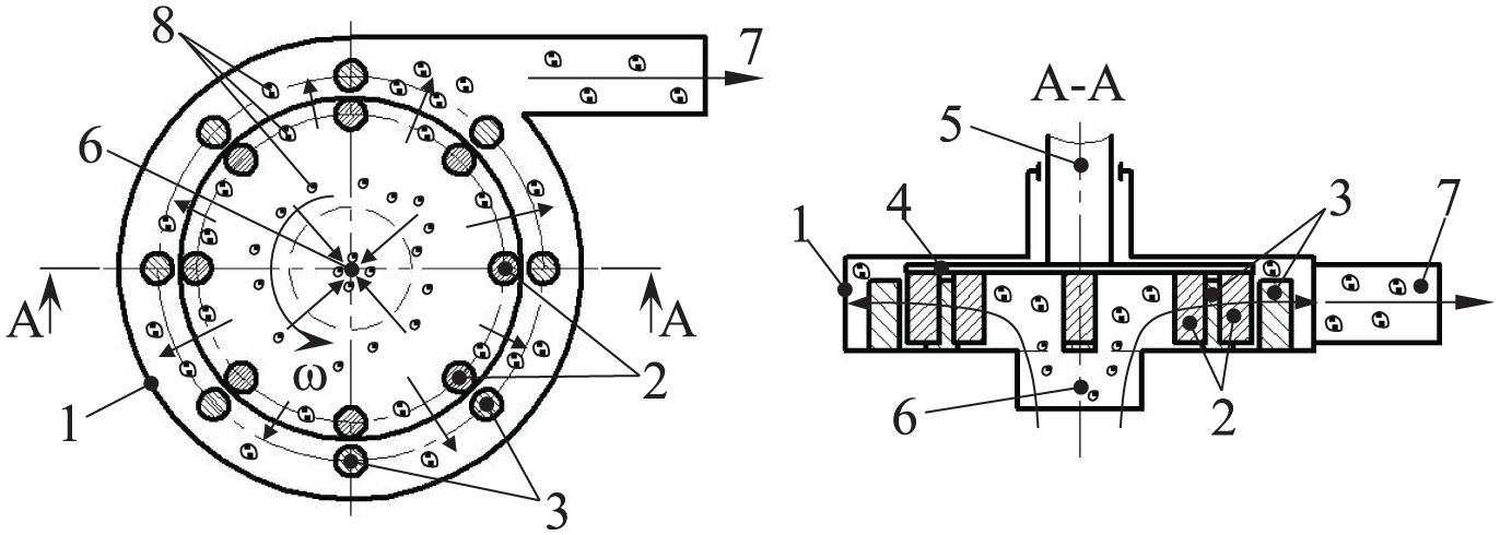
To enhance the efficiency of the grinder through innovative technical solutions and a novel operational scheme incorporating the integration of centrifugal, aerodynamic, and oscillatory processes the energy intensity of the grinding process was increased in a localized annular zone adjacent to the rotor. This was achieved by inverting the operational scheme of a typical dismembrator without significant changes to its design, according to a patented fine grinding method. 10 The new operational scheme and design of the inverted impact grinder (Figures 1 and 2) combine the working principles of a dismembrator and a jet mill within a single unit, thereby eliminating many of the shortcomings inherent to each device individually.16–18 As a result, the energy intensity and velocity-force characteristics of the grinding process are increased, the residence time of particles in the grinding zone is extended, and the number of impact interactions per unit time is maximized. This improves the probability of particle interaction with the working elements, enhances impact force utilization efficiency, and broadens the potential for process control. Additionally, feeding the material together with pressurized air compensates for the adverse effects of aerodynamic forces generated by the rotating working element. Furthermore, in the inverted grinder, high-frequency oscillatory movements of material particles are induced by centrifugal and aerodynamic forces, which intensify the process or enhancing process intensity.16–20

New inverted impact grinder.

Operating scheme of the inverted impact grinder.
The new inverted impact grinder (Figure 2) operates as follows. The grinder rotor, equipped with a series of impact pins along its periphery, is rotated at a maximum speed sufficient to achieve the target fineness. Material is fed into the peripheral zone of the grinder via an external air stream, with pressure and velocity adjusted to match the rotor rotation speed, ensuring the discharge of properly ground particles. The rotating rotor generates centrifugal force and centrifugal air pressure, which counteract the pressure of the external airflow that transports the material.
In the annular zone near the rotor, the material-air stream moving from the periphery collides with the centrifugal airflow moving outward from the rotor. This interaction exposes material particles to turbulence, high-frequency pressure pulsations, and centrifugal forces from the rotating rotor, causing them to undergo high-frequency chaotic oscillations as they move back and forth between the rotor and the periphery. Through frequent repeated impacts from the mobile impact pins on the rotor, collisions with the stationary pins on the stator housing and between particles, as well as through abrasion, the particles experience high-energy mechanical forces and are intensively ground.
As particles are reduced to the required size, the pressure of the external air stream, which surpasses the combined effects of centrifugal force and centrifugal air pressure from the rotating rotor, directs them towards the central discharge outlet, through which they exit the grinder.
By adjusting the pressure and velocity of the external material-air stream and the rotor rotational speed, it is possible to control the energy intensity of the process, grinding fineness, productivity, particle size distribution, and other performance parameters, thereby optimizing the quality of the grinding process.
The scientific and practical novelty underlying the new operational scheme and design of the inverted impact grinder not only provides extensive opportunities for its further improvement but also potentially introduces a new direction in the development of grinding equipment.
Theoretical Description of Particle Fracture by Free Impact
In material grinding, it is essential to quantitatively determine the parameters characterizing the grinding process and also the operational parameters of the grinder. This requires an appropriate mechanical and mathematical model. Fine grinding processes are inherently complex and challenging to predict using theoretical models. Material grinding requires a quantitative assessment of both the process parameters and the operational characteristics of the equipment, which in turn demands a suitable mechanical and mathematical model.
Fine grinding processes, in particular, are complex and difficult to predict theoretically. As a result, a large number of grinding models currently coexist, each applicable under specific grinding conditions. Over time, various researchers (Griffiths, Taggart, Rittinger, Kirpichev, Kick, Bond, Ray, Peter, Rumpf, Kafarov, Orowan, Irwin, Barenblatt, Rebinder, Inglis, Guillot, Charles, Rundqvist, Khodakov, Levenson, Sidenko, Brach, Karmazin, Tatur, Balovnev, Vogel, Poikert, Kalman, Reynolds, Schönert, Tavares, and many others) have proposed a wide range of theories and hypotheses to explain the mechanisms of fracture in solid materials. These models attempt to establish correlations between fracture mechanisms and energy consumption.1–4,24
According to the fundamental hypotheses, particle fracture mechanisms are determined based on the minimum potential energy state of the deformed system. These hypotheses also take into account various factors influencing the fracture process in solids. However, existing grinding hypotheses primarily provide a qualitative understanding of the grinding process, whereas practical applications require a quantitative framework.
The key limitations of current grinding hypotheses that hinder their practical application include:
– the need to empirically determine several coefficients that differ for each material;13–15
– the requirement to determine the magnitude of forces of various natures;20–22
– the complexity of the mathematical apparatus and its practical implementation (common to nearly all models);16–18
– reliance on statistical or empirical models, or probabilistic approaches;11–13
– narrow applicability outside the scope considered in this study (e.g., high-pressure roll crushing models by Schönert);2,5
– the necessity of using specialized computational software (e.g., Tavares’ grinding model based on the discrete element method). 6
Therefore, existing grinding models possess significant drawbacks, failing to fully meet the criteria of simplicity and engineering applicability outlined in this study. Moreover, they are incapable of calculating some critical process indicators, such as the volume of material fractured per single impact.
It is important to recognize that accounting for all factors influencing particle fracture is highly improbable, which makes the development of an accurate and practically usable grinding theory an extremely challenging task.
Hence, there remains a relevant task to develop a simple, yet sufficiently accurate and reliable mathematical model or engineering method. Such a method should allow for at least an approximate prediction of grinding results and determination of the key grinder parameters.
The applied theoretical description of particle grinding by impact relies on several initial assumptions. For example, the greatest deformations and stresses in a particle occur at its point of contact with the working element; the fracture process of a fine particle is approximated by the separation of local material volumes upon each impact from the working element; and the ultimate stress limit of the particle material can be considered a general characteristic of its macro- and microstructural state.
Based on classical grinding hypotheses and principles of the mechanics of elastically deformable solid bodies,12–15 a theoretical equation was derived to describe and model the fracture process of a solid spherical particle by impact. 17 Additionally, an applied calculation methodology was developed, based on the determination of the stresses occurring within a spherical particle during elastic deformation until fracture.
Consider the calculation scheme presented in Figure 3. The action of the working element on the elastically deformable spherical particle is represented as a concentrated force P, normal to the surface of the working element. Let A be a point within the particle, whose position is determined by polar coordinates r and β. Through point A, we define a plane perpendicular to r and determine the magnitude of the normal stress σr acting on this plane.
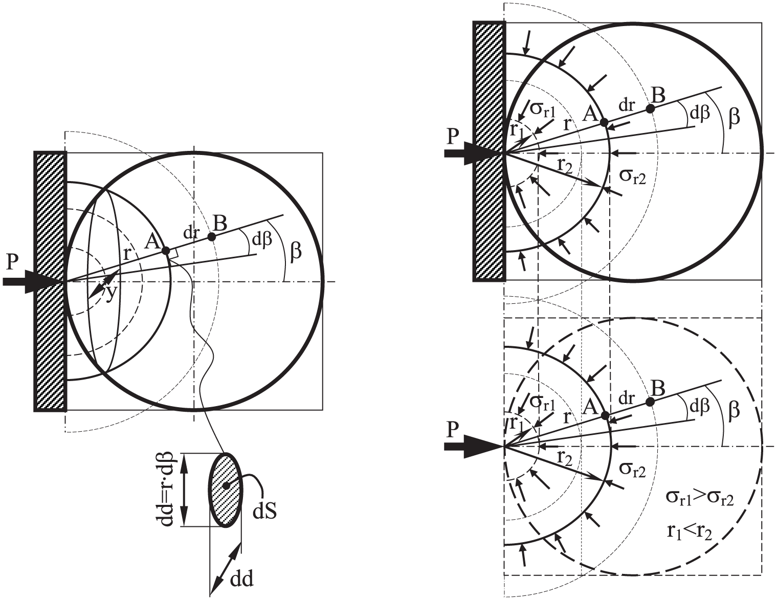
Force distribution scheme in an elastic spherical particle.
The farther point A is from the force application point P, the smaller its displacement. The greatest displacements occur along the force direction P, while with increasing angle β, displacements decrease and become zero at the boundary plane. Suppose point A moves by a distance dr to point B. The relative strain along the segment dr is determined under the assumption of a linear relationship between stress and strain, with the radial compressive stress considered constant across the infinitesimal area dS of the analyzed element.
Displacement of point A:

where ν- the proportionality coefficient, m2.
The displacement of point B, similar to the previous case, is determined as follows:

If infinitesimally small quantities are neglected, the relative deformation er of segment dr will be:

Due to the assumed direct proportionality between stress and strain, the value of the radial stress causing the relative compression of the considered element is:

where ξ- the proportionality coefficient, Pa.
The product of the coefficients (ξ·ν), which represents the force, is determined from the equilibrium equation:

Solving this equation and determining that ν·ξ = P/π (N), and substituting this expression into the stress formula, we obtain the final formula for determining radial stresses in the destroyed local volume of the material particle:

Assuming that, due to the small size of the particle, the displacements of all its points along the radius r and the corresponding stresses are uniform and independent of the angle β (Figure 3), the acting stresses can be determined as the average stresses (σr cp), i.e.:

where
The proposed grinding model, represented by the derived mathematical relationship (7), provides a theoretical description of the particle breakage process and allows for the quantitative determination of parameters characterizing both the grinding process and the operating conditions. This model allows one to calculate and predict grinding performance, and to evaluate the operation of grinding machines based on such parameters as the particle size of the feed material, the grinding limit, the volume of material fractured per single impact, among other factors. It provides physically and mechanically interpretable and practically applicable theoretical relationships that, despite certain simplifications, permit engineering-level estimations without the need for specialized software. This facilitates engineering calculations during the design of impact-type grinding machines.
One limitation of the proposed model lies in its primary applicability to free-impact grinding processes, as it is based on the selective interaction between the working element and the particle.
Although the proposed model may not be significantly superior to existing ones, it introduces a certain degree of novelty, as the authors are unaware of analogous approaches specifically describing the grinding process in such terms. Moreover, in certain cases, the model may prove more convenient for practical use, particularly in applications related to specific grinding conditions in impact-type grinders, which aligns with the practical scope of this study.
Based on equation (7), it is possible to calculate the particle volume destroyed per impact, determine the number of impacts required to grind a particle to the desired size, predict changes in particle sizes and grinding outcomes, and define the optimal velocity-force parameters of the grinding process along with the structural and process parameters of the grinder, depending on specific process conditions.
To determine the number of impacts required to grind a particle from its initial to the desired size, we consider the following initial data: particle shape – spherical; initial particle size (ball diameter) dvh = 0.001 m (1 mm); particle size at the outlet of the grinder (ball diameter) dvyh = 0.000005 m (5 μm); particle strength limit [σrcp] = (40…60) ·106 Pa (for quartz sand), moreover, the strength of a particle may increase during the grinding process, which must be taken into account directly in the model calculations—for example, based on the Hall–Petch relationship; and the particle strength may increase as it is ground; particle density ρ = 2600 kg/m3; initial particle mass m = 1,36·10−6 kg.
The model assumes that each impact results in material fracture, as accounting for impacts that do not lead to fracture is practically impossible.
Using equation (7), we determine the depth r of particle fracture per impact (collision) with the working element:

The velocity v of the grinder hammers (impact velocity of the particle and the hammer) can be determined as follows:

where n – the rotation frequency of the crusher rotor, rpm; R = 0.2 m is the radius of the crusher rotor beaters, m.
The calculation yields: at n = 2000 rpm, v = 42 m/s; at n = 3000 rpm, v = 63 m/s; at n = 5000 rpm, v = 105 m/s.
Next, we determine the volume V1 of the particle material (approximately determined by the spherical segment of height r), which was destroyed by one impact of the working element:

Next, the remaining volume of the particle after impact is determined as follows:
The particle size (sphere diameter) is recalculated based on the newly obtained volume. Vi:

The step-by-step calculation is repeated until the diameter d reaches the required value of dvyh =5·10−6 m (5 μm).
The results of the particle grinding process from 1 mm to 5 μm for impact velocities v = 42 m/s, v = 63 m/s, and v = 105 m/s are presented in the graphs in Figure 4. These results indicate that grinding from 1 mm to 50 μm (a 20-fold reduction) and from 50 μm to 5 μm (a 10-fold reduction) each occurs over approximately half of the total number of impacts. If the calculation is extended further, grinding from 5 μm to 1 μm (a 5-fold reduction) requires approximately the same number of impacts as the previous steps.

Results of the particle grinding process calculation.
This suggests that larger particles are ground more intensively, but as their size and mass decrease, the grinding rate slows down, approaching zero. This observation aligns with the general trend of the ‘grinding stoppage’ effect as particle size decreases5,11,13,16,17 and confirms that the developed theoretical model accurately represents the real grinding process.
A comparison of the number of impacts per particle at different working element velocities shows that increasing the impact velocity by 1.5 times results in a 1.5–2 times increase in grinding intensity.
In practical applications, the ability to theoretically estimate – even with approximate accuracy – the number of impacts required to reduce a particle from its initial to final (desired) size enables the prediction of grinding performance. Adjusting the number of impacts within the grinding chamber or modifying the velocity of the working element allows for the determination of the number of grinding stages or the required residence time of the material, thus enabling effective control over grinding process parameters. However, this approach requires a clear understanding of the relationship between the number of impacts and the grinding time.
Determination of optimal operating modes for the inverted impact grinder
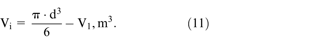
To describe the processes occurring within the inverted impact grinder, the motion of a solid particle of the ground material is analyzed in the force field generated inside the grinder, consisting of both aerodynamic and centrifugal forces (Figure 5). Aerodynamic forces include the frontal pressure force F exerted by the external airflow on the material particles, and the centrifugal pressure force FC generated by the air expelled from the rotating rotor, acting in opposition to the frontal pressure of the incoming external flow. The centrifugal force C, caused by the rotation of the rotor, also acts in opposition to the external airflow pressure.

Forces acting on particles in an inverted grinder.
The material particles are removed from the grinder under the condition that the force of the frontal pressure of the external flow F is greater than the sum of the centrifugal force C and the centrifugal force of pressure FC. Up to this point, the particle is in the grinder. The condition of the state of equilibrium preceding the particle exit from the grinder is determined by the equality:

For practical purposes, the dependences of the critical diameter d of the particles on the parameters of the grinder are necessary – on the angular speed of the rotor d = f(ω) and on the pressure of the external flow d = f(p). We will obtain them by substituting the expressions for determining the force of the frontal pressure of the external flow F, the centrifugal force C and the centrifugal force of pressure FC into the adjusted formula (13)
where k: the drag coefficient; ρв: the air density, kg/m3; d: the particle diameter, m; v: the external air flow velocity, m/s; ρch: the particle material density, kg/m3; R: the rotor radius, m; ω: the angular velocity of the rotor, s−1; vC: the centrifugal air velocity, m/s.
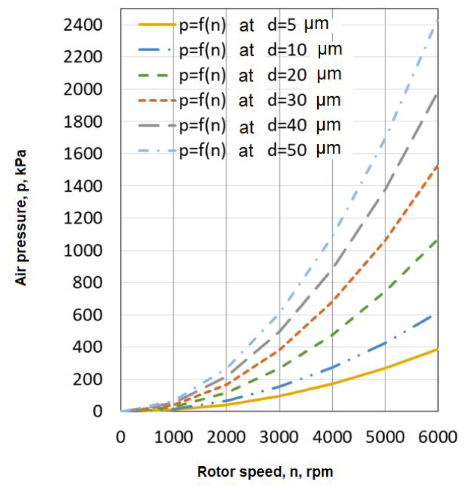
Based on dependence (14), we construct graphs of the change in forces C, FC and F from the diameter d of the particle (Figure 6), from which it is clear that with a given combination of forces F, C and FC, obtained at a rotor speed of n = 5000 rpm (523 s−1) and an external flow pressure of p = 167 and 364 kPa, particles with a size of dkr≤5 μm (at p = 167 kPa) and with a size of dkr≤30 μm (at p = 364 kPa) should theoretically be removed from the grinder, and particles larger than the size dkr should remain in the grinder until a critical value is reached.

Dependences of forces F, C and FC on particle diameter (ω = 523 s−1).
The general dependence of the particle diameter on the operating parameters of the grinder in general form is d = f(ω, vC, v, p, R). In this case, the air speed v = f(Δp), the centrifugal speed vC = f(ω), and the angular speed of the rotor ω is in practice more difficult to change than the air pressure p. Therefore, the refined dependence of the particle diameter on the operating parameters of the grinder will have the form d = f(p, ω, R), where, as a rule, R = const.
Having determined the expressions for the external air flow speed and the centrifugal air speed, after substitutions in formula (14) and transformations, we obtain an expression for determining the critical particle diameter depending on the angular speed of rotation and the radius of the rotor and the pressure of the external air flow, that is, d = f(p, ω, R), where R = const:

where φ: the coefficient taking into account the speed losses; p: the pressure of the external air flow in the grinder, Pa; pa: the atmospheric pressure at the outlet of the grinder, Pa; δ: the thickness of the rotor fingers, m.
Where does the excess pressure Δp of the external air flow required to remove a particle of size d from the grinder come from, at a certain angular velocity of the rotor ω:
Preliminary graphs have been constructed based on equations (15) and (16), illustrating the theoretical dependencies: excess pressure of the external airflow as a function of the angular velocity of the rotor for different particle diameters (Figure 7(a)); particle diameter as a function of the excess pressure of the external airflow for different values of the angular velocity of the rotor (Figure 7(b)) at R = const.

Theoretical dependencies of external airflow pressure on rotor angular velocity (a) and particle diameter on external airflow pressure (b).
The grinder parameters are considered optimal when the output material consists of particles with the required size corresponding to a specific operating mode. To produce particles of the desired size, the external airflow pressure must be properly aligned with the rotor rotation speed, which is governed by the force required to fracture particles of a given strength, assuming a constant rotor radius.
Efficient operation, the required grinding fineness, and optimal productivity of the inverted impact grinder can only be ensured by a precise alignment between the external airflow pressure and the rotor rotation speed. Increasing the energy intensity of the process and the grinding fineness while maintaining grinder productivity can be achieved by raising the rotor’s rotational speed, synchronized with an increase in the velocity of the airflow carrying the ground material.
Experimental studies of the inverted impact grinder
Experimental studies were conducted to validate the theoretical models and assess their consistency with actual operating conditions by determining key grinder performance parameters.
The experimental investigation of the inverted grinder includes the following stages:
Empirical development of a methodology for calculating and predicting the grinding process based on theoretical relationships for determining the number of impacts required to reduce particle size from the initial to the final dimensions, and establishing an empirical correlation between the number of impacts and grinding time.
Investigation, validation, and evaluation of the theoretical justification for the operating modes of the new inverted grinder.
Assessment of the operability, efficiency, and practical applicability of the newly developed inverted grinder.
During the experiments, the following equipment and materials were used:
The dismembrator (Figure 8) consists of a housing (1) in which a rotor (4) with rigidly fixed movable impact pins (2) is mounted. Additionally, stationary pins (3) are fixed inside the housing around the rotor. The raw material enters through the feed opening (6) into the center of the rotor (4), is accelerated on the rotor, and thrown by centrifugal forces onto the impact pins (2) attached to the rotor. As the material particles (8) pass through these pins, they undergo impacts and are crushed. Upon leaving the rotor (4), the material particles (8) are thrown onto the stationary pins (3) of the housing (1), where they are further crushed by impact. After passing through a series of stationary pins (3), the crushed material is discharged from the dismembrator through the outlet pipe (7), which is mounted tangentially to the housing.
Schematic of a typical dismembrator operation.
The inverted grinder was obtained by reorganizing the operating scheme of the dismembrator – reversing the direction of feed and discharge – without any modifications to its construction. It also has a motor power of 1 kW and a rotor diameter of 0.4 m.
- The PSKh–10A device for determining the specific surface area and mean particle size of the material (Figure 9), and PCE-WS-30 electronic scales for weighing material samples.
The PSKh–10A was manufactured by Scientific Instruments Laboratory LLC (Russia). It measures the specific surface area and average particle size of powders using the air permeability method for a powder sample of defined mass (or volume). Measurement accuracy: ±1 cm2/g for specific surface area, ±0.1 μm for particle diameter.

Diagram (a) and external view (b) of the experimental setup for studying the inverted impact grinder, and PSKh-10A device (c).
The PCE-WS-30 electronic scales were produced by Wöhler MGKG, PCE Group Co. KG (Germany). Mass is measured through strain gauge sensors under load, with signals converted into display readings. Measurement accuracy: ±0.5 g.
- Quartz sand (0.5–1 mm fraction) and aged cement, opened nine months prior to testing, were used as grinding materials.
Figure 9 shows the experimental setup for studying the inverted grinder.
Empirical development of a methodology for calculating and predicting the grinding process
To evaluate the theoretical relationships for determining the number of impacts required to reduce the particle size from the initial to the final value, and to empirically develop a predictive methodology for the grinding process, quartz sand with a particle size of 0.5–1 mm was ground using both the inverted grinder and the standard dismembrator. During these experiments, the time required to reach the target particle size was measured, and the actual particle size of the ground material was verified. Tests were conducted at impact velocities of v = 105 m/s (n = 5000 rpm) and v = 63 m/s (n = 3000 rpm). Each grinding condition was repeated at least five times to ensure the consistency and reproducibility of the results.
During the experiments, the grinding time in the inverted grinder was measured as follows:
The inverted grinder was sequentially adjusted to operate under various air pressure and rotor speed settings expected to yield output particle sizes of 50, 40, 30, 20, 10, and 5 µm. For each setting, a 2 kg batch of initial material, measured by the chamber feeder’s volume, was fed into the grinder. As the material began to exit the machine, its particle size was continuously monitored. The average time from the start of feeding to the completion of material discharge was recorded as the grinding time corresponding to the target particle size.
The grinding time in the standard dismembrator was determined as follows: a 2 kg batch of raw material was loaded into the dismembrator, and the ground product was collected at the outlet. The time from the moment of loading to the end of material discharge was recorded as the total grinding time.
The particle size of the ground material was verified as follows: a sample of 8.6 g of the ground product was loaded into the PSKh-10A device, which measured the specific surface area (cm2/g) and the average particle diameter (µm).
Subsequent data processing enabled the construction of graphs illustrating the entire grinding process from the initial to the final particle size (Figure 10).

Grinding process graphs in the new inverted impact grinder (a) and the standard dismembrator (b).
To enable the prediction of obtaining a final product with the required particle size in an impact grinder, the experimental results for grinding time in the new inverted impact grinder (Figure 10(a)) and the standard dismembrator (Figure 10(b)) were compared with the theoretical calculations of the number of impacts required to grind the material to the desired fineness (Figure 4).
Based on this comparison, the average number of impacts per unit time required to achieve the target particle size was determined (Figure 11(a), 11(b), 11(c)). For both types of equipment, the average number of impacts per unit time necessary to reach the required particle size falls within the range of 1.4–1.6.

Average number of impacts per unit time required to achieve the target particle size in the inverted impact grinder (a, b) and the standard dismembrator (c).
In practical applications, when predicting the production of a final product with the required particle size, the number of impacts needed for grinding should be calculated using the methodology described above. The obtained number should then be divided by the established average number of impacts per unit time (1.4–1.6) to estimate the approximate grinding time required for a particle to be reduced from its initial to final size, or the minimum residence time of the particles in the grinder.
For high-strength materials or fine-dispersed media, the average number of impacts per unit time can be assumed to range from 1 to 1.5, while for low-strength materials or coarse-dispersed media, it can range from 1.5 to 2.
Investigation, validation, and evaluation of the theoretical justification for the operating modes of the new inverted grinder
To validate the theoretical basis for the operating modes of the new inverted impact grinder, experiments were carried out using sand with a particle size range of 0.5–1 mm. Specifically, the relationship between rotor speed, external airflow pressure, and the resulting particle size was examined. The experiments were conducted at rotor speeds of n = 5000 rpm and n = 3000 rpm.
The experiments revealed that, for the given grinder design, to achieve the required particle size at both rotor speeds, the external airflow pressure must be 4–4.5 times higher than the theoretically calculated value. This should be taken into account in equation (10). The introduction of a correction factor of 4–4.5 into equation (5) makes it possible to compensate for unaccounted conditions in the flow of the material–air mixture and pressure losses, unaccounted flow resistances, inaccuracies in the selected coefficient values in the formulas, possible velocity drop of the flow at the inlet to the chamber feeder and grinder, as well as other factors contributing to the actual pressure deficiency.
The results of theoretical calculations and experiments are presented in Figure 12. Figure 12(a) shows the experimental dependencies of particle diameter on pressure, considering a 4-fold increase in theoretical pressure, compared with the theoretical dependencies of particle diameter on pressure under the original theoretical assumptions. Figure 12(b) shows the experimental dependencies of particle diameter on pressure, considering a 4-fold increase in theoretical pressure, compared with the calculated dependencies of particle diameter on pressure, also adjusted for the 4-fold increase in theoretical pressure.

Practical dependencies of the diameter of ground particles on the actual pressure of the external airflow.
Given the stability of the ratio between theoretical and experimental values for the combination of rotor speed and external airflow pressure at two different rotor speeds, it can be assumed that this relationship remains valid for other effective working speeds within the range of 3000–6000 rpm.
Based on this assumption and considering the identified ratio of theoretical to experimental external airflow pressure values (equal to 4), graphs were constructed (Figure 13) to determine the optimal combination of rotor speed and external airflow pressure for achieving different particle size values of the final product at the grinder outlet.
Operating combinations of rotor speed and external airflow pressure for obtaining different particle size values of the final product.
Using the graphs in Figures 12 and 13, it is possible to practically determine the optimal external airflow pressure values based on the rotor’s angular velocity to achieve the desired grinding fineness. Additionally, the necessary external airflow pressure for the discharge of particles of a specific size from the grinder can be determined for a given rotor speed.
Evaluation of operability, efficiency, and practical applicability of the new inverted grinder
To verify and assess the operability, efficiency, and practical applicability of the newly developed inverted grinder, comparative experimental studies were carried out. These experiments examined the changes in specific surface area and particle size of aged cement as a result of free-impact grinding performed using both a standard dismembrator and the new inverted grinder.
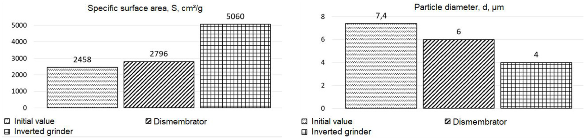
Before conducting the experiments, samples of aged cement were collected, and their initial specific surface area S (cm2/g) and average particle size d (μm) were determined using the PSKh-10A device. The measurement results are presented in Table 1.
Characteristics of the initial aged cement.

Average values based on three measurements: specific surface area S = 2458 cm2/g; average particle diameter d = 7.4 μm.
Initially, the efficiency of a typical dismembrator was determined. A sample of stale cement was passed through the grinder at a rotor speed of 5000 rpm. The same sample of material (cement) was processed sequentially. After each pass, samples were taken from the volume of crushed material and processed on a PSKh-10A device. The results obtained are presented in Figure 14.

Results of cement grinding (specific surface area and average particle diameter) in a typical dismembrator.
As seen in Figure 14, the fifth and subsequent passes through the grinder demonstrated that the specific surface area and average particle size of the cement remained practically unchanged, while energy consumption continued to increase. This indicates that further grinding under the given operating scheme, parameters, and conditions is inefficient. It was observed that the grinding time for cement in the standard dismembrator is relatively long, while the grinding effect remains minimal. Thus, in a standard dismembrator, effective grinding is only possible for materials with a relatively large initial particle size (∼1 mm), reducing them to 50–100 μm. The results of the experimental studies of the standard dismembrator are presented as graphs in Figure 15.
Cement grinding results in the standard dismembrator and the new inverted impact grinder.
During the tests, the new inverted impact grinder was configured based on theoretical graphs from Figures 12 and 13 to achieve ground material particle sizes of approximately 5 μm. At a rotor speed of 5000 rpm, the excess air pressure at the grinder inlet was set to 260–270 kPa (2.6–2.7 bar). A sample of raw cement with a specific surface area of S = 2458 cm2/g and an average particle size of d = 7.4 μm was processed through the grinder. After grinding, samples were taken and analyzed using the PSKh-10A device. The average result for cement after a single pass through the grinder was: S = 5060 cm2/g, d = 4.0 μm.
The following overall results were obtained during the study of cement grinding. The total cement grinding time in a typical dismembrator over 5 passes is about 40 s (0.67 min), which, at a drive power of 1 kW, results in energy consumption of:

The average grinding time of the material in the inverted grinder per pass is about 18 s (0.3 min), which, at a drive power of 1 kW, results in energy consumption of:

Taking into account the energy consumption of the compressor over the same period (18 s (0.3 min)) at a compressor power of 1 kW, the total energy consumption of the inverted grinder amounts to:

which is slightly lower than the energy consumed by the typical dismembrator, while achieving a significantly higher specific surface area and a smaller average particle size (5060 cm2/g vs 3534 cm2/g and 4 µm vs 6.2 µm, respectively). Moreover, the obtained specific surface area corresponds to the optimal range for Portland cements (5000–6000 cm2/g), which cannot be achieved in a standard dismembrator. The possibility of regulating grinding fineness and classifying ground particles during the grinding process was also confirmed.
The comparative results of cement grinding in the new inverted impact grinder, presented as graphs in Figure 15, demonstrate its superior efficiency.
Additionally, based on the experimental results of grinding cement from an initial particle size of 7.4 μm to a final size of 4 μm, the theoretical number of impacts required for material grinding was calculated to be 26 impacts (Figure 16).

Number of impacts required for cement grinding in the inverted impact grinder.
Given the grinding time of 18 s, the average number of impacts per unit time required to grind cement from 7.4 μm to 4 μm was calculated as 1.44. This confirms the previously established value of 1.4–1.6 impacts per unit time, which was used for predicting material grinding time.
Conclusion
A novel inverted impact grinder with an innovative operational scheme, enhanced energy intensity, and particle size classification has been proposed. The new design improves process parameters, enhances efficiency, and expands the capabilities of the grinding process.
A mechanical-mathematical model and engineering methodology were developed, allowing for theoretical calculations and predictions of particle loading characteristics, grinding process parameters, and grinder performance. Refined analytical relationships and graphs have been obtained to determine the optimal operating parameters of the inverted grinder.
The inverted grinder with its novel operational scheme experimentally demonstrated its operability, advantages, efficiency, practical applicability, and promising potential. This study successfully addresses the intensification of the fine grinding process and the improvement of fine grinding machinery based on new principles of operation and innovative design solutions aimed at increasing grinding efficiency and meeting the growing demand for ultra-finely ground materials.
New insights have been obtained into one of the potential approaches to enhancing the efficiency of fine grinding - namely, the synergistic integration of operational principles from jet and aeroballistic grinders. The new operating concept of the inverted grinder, which involves exposing particles to high levels of mechanical energy, opens up new possibilities for the development of cost-effective grinding technologies, including reduced processing times.
This concept lays the foundation for future research in the field of fine grinding technologies, particularly in the development of processes and equipment based on complex synergistic impact mechanisms, where particles are subjected to high-energy free-impact forces combined with integrated action from multiple grinding principles within a single machine design.
Footnotes
Handling Editor: Sharmili Pandian
Funding
The author(s) disclosed receipt of the following financial support for the research, authorship, and/or publication of this article: This research was funded by the Science Committee of the Ministry of Science and Higher Education of the Republic of Kazakhstan (Grant No. AP23488405 ‘Development of innovative equipment for grinding materials with increased efficiency’).
Declaration of conflicting interests
The author(s) declared no potential conflicts of interest with respect to the research, authorship, and/or publication of this article.