
Abstract
The underwater towing system is widely used in the measurement of underwater noise and the exploration of natural resources. In underwater detection, the attitude of the underwater towing system greatly influences the detection accuracy. Therefore, it is important to accurately predict the attitude of the towing system during its design and application. In this paper, the force and moment equilibrium equations for the towing cable and the towing array are established by analyzing the steady-state of the towing system. The iterative solution method for nonlinear equations is used to solve the problem, leading to a rapid prediction based on the multi-segment rod model. Since the attitude is significantly affected by the drag coefficient, selecting an appropriate drag coefficient has always been a challenge. In this paper, a drag coefficient formula is established by fitting experimental data. Based on the muti-segment rod model and the drag coefficient formula, an attitude prediction method for the towing system is developed. The results are validated through experiments and examples from the reference, confirming the accuracy of the modeling method and the drag coefficient. The influence of each parameter of the towing system on its steady-state motion is studied.
Introduction
The underwater towing system is a basic underwater exploration equipment, which consists of towing cable, towing array, tugboat and ancillary equipment. It has high reliability, safety and recoverability, so it is widely used in marine resource investigation, scientific research and underwater military anti-submarine and other fields. 1
Nevertheless, the underwater environment exerts an influence on the accuracy of data acquisition. For instance, the complex hydrodynamic load result in alterations to the position and attitude of the towing cable, which consequently lead to discrepancies in the position of the underwater detection equipment, thereby affecting the data obtained from the acquisition. Consequently, scholars have conducted research to ascertain the accuracy of measurements obtained from the underwater towing system.
Building on its proven robustness, the towing system is also pivotal in advanced sonar applications. In Synthetic Aperture Sonar (SAS), for example, a towed array must maintain a tightly controlled trajectory to achieve the fine spatial sampling needed for high-resolution image reconstruction; recent studies by Zhang et al. demonstrate how optimized towing configurations improve image fidelity and extend swath coverage.2,3 Similarly, in sub-bottom profiling, a stable tow-fish deployment ensures consistent depth control and signal penetration, as shown in the works of Tan et al. and Sun et al., which integrate towing platforms with profiling heads to map sub-seafloor structures with enhanced clarity.4,5
The analysis methods can be divided into two categories: dynamic time-domain analysis 6 and steady-state analysis. Three main modeling approaches are commonly used: (1) the lumped mass method, (2) the finite element method, and (3) the finite difference method.
In 1999, Huang proposed a method for determining the state of the towing array known as the lumped mass method. 7 Driscoll et al. established the motion equation of Remotely Operated Vehicle (ROV) by this method and predicted the tension of the underwater towing cable.8–10 Buckham and Nahon used the lumped mass method to build a three-dimensional model of the ROV.11,12 Gomes carried out relevant research on the dynamic attitude of the underwater towing system. 13 Gonzalez et al. studied the problem of posture and tension during release and retraction of the streamer system. 14 Zhu proposed a novel elemental reference frame based on the lumped mass method for the efficient analysis of the dynamics of marine cables. 15 Gao and Wang also used this method to simulate the attitude of the underwater towing cable system. 16 Wang et al. analyzed the influence of the guide rod on the towing system through the lumped mass method. 17 Based on the lumped mass method, Samuel discretized the underwater towing system into a hinge model and calculated its attitude, thereby improving prediction accuracy. 18
The lumped mass method discretizes the towing system into a series of mass points and connecting elements, enabling the modeling of large deformations and complex dynamic responses. It is widely used due to its conceptual simplicity and flexibility. However, this approach typically requires solving large systems of differential equations over time, resulting in high computational costs and potential numerical instability in long-term simulations. Moreover, it is primarily suited for dynamic analyses and is less efficient for steady-state attitude prediction, which is the focus of this study.
In the application of the finite element method, Breukels and Ockels developed a kite cable dynamics simulation using this method. 19 Zhu and Sun et al. improved the finite element method and used the node position instead of the node displacement to analyze the dynamics of the underwater towing system.20,21 Wang et al. and Zhou et al. used this approach to numerically analyze the submarine cable.22,23 Park and Kim used the finite element method to study the coupled dynamics of underwater towed bodies. 24 Zhou et al. proposed a novel finite element formulation in Hamiltonian formalism for the global nodal position discretization of submarine cables, which can be utilized to analyze the attitude of submarine cables. 25 Gharib et al. developed a comprehensive model to analyze the static and dynamic behavior of marine towed cable-array systems based on vessel motion, which he subsequently validated through numerical simulations. 26
Finite element methods offer higher accuracy by discretizing the cable into elements and directly solving for nodal positions or displacements. They are capable of handling material nonlinearity and complex boundary conditions. Nevertheless, finite element formulations usually involve the assembly and inversion of large sparse matrices, demanding substantial computational resources. For real-time or rapid preliminary analyses of underwater towing systems, these methods may not be practical due to their computational intensity.
In the application of the finite difference method, Ablow and Schechter pioneered the application of the finite difference method in cable dynamic analysis, leading to the determination of the corresponding underwater attitude of the towing array. 27 Howell refined the finite difference method to obtain a stable form for calculating cable motion. 28 Lee et al. employed the finite difference method to construct a model of a flexible pipe. 29 Zhang and Li analyzed the axial dynamic tension response of a depth water riser by a linear quadratic Gaussian control strategy based on the finite difference method. 30 Guo et al. used this method to model the attitude of the towing cable with consideration of the vortex shedding effect. 31
The finite difference method discretizes the continuous cable equations into algebraic forms, facilitating efficient numerical solutions. It has been successfully applied to dynamic and static modeling of cables. However, this method often struggles with numerical stability, particularly under large deformation conditions. Furthermore, the method's performance heavily depends on the discretization scheme and step size selection, which can limit its robustness for steady-state applications.
To address the limitations of the aforementioned methods in fast and stable steady-state attitude prediction, this paper proposes a multi-segment rigid-rod equilibrium model. By simplifying the cable into a series of rigid rods connected by joints and solving the static force balance recursively, the model achieves a significant reduction in computational complexity while maintaining essential physical accuracy. Compared to traditional finite element methods, this approach offers faster convergence and better suitability for engineering design and preliminary assessments.
According to reference 32, the selection of drag coefficient also has a great influence on the attitude of the underwater towing system. 32 In order to improve the calculation accuracy, this paper uses some experimental data to fit the drag coefficient formula. The accuracy of the drag coefficient is improved. The tension distribution, towing array depth and towing attitude of the towing system can be predicted quickly and accurately with different speeds of the tugboat and different geometric parameters of the towing system. The numerical calculation method established in this paper can not only improve the prediction accuracy but also provide technical support for the design and application of the underwater towing system.
Mathematical model
The methodological framework of this study is illustrated in Figure 1. The workflow begins with the acquisition of experimental data and initialization of system parameters, including geometric configurations and hydrodynamic properties of the underwater towing system. A critical drag coefficient fitting process is then implemented, where hydrodynamic forces are calibrated against experimental measurements to enhance model fidelity. An error threshold mechanism governs the iterative refinement: if the deviation between simulated and experimental results exceeds predefined tolerance limits, hydrodynamic parameters are systematically adjusted until convergence is achieved.

The block diagram of this study.
Towing system and coordinate
The underwater towing system is divided into a towing cable and an array, as illustrated in Figure 2, which shows the Cartesian coordinate system of the underwater towing system. The origin (towing point) is the junction point between the towing cable and the horizontal plane (water plane). The x-axis is parallel to the horizontal plane. (The direction of the x-axis is opposite to the tugboat’s forward direction.) The y-axis is the opposite of gravity.

Underwater towing system and coordinate diagram.
Theoretical model
A theoretical model of the underwater towing system is established. Each part of the system is divided into multiple segments of homogeneous rigid rods. The principles of the division are as follows:
(i) The lengths of different segments of the rod are uniform.
(ii) The points of tension application are located at the head and tail ends of the rod.
(iii) The gravity and buoyancy are concentrated on the geometric center of each rod.
Based on the principle, the towing cable and the array are divided into N segments of rigid rods. From the towing point to the array, the rod numbers are 1∼N. From the head point to the end of the array, the number of rod nodes is 1∼N+1. Node M is the point of connection between the towing cable and the array. The joint of the trailing tugboat and the towing cable (x1, y1) is (0,0). The length of each rod is L. The global discrete diagram is shown in Figure 3.

A global discrete model of underwater towing system.
In Figure 4, the theoretical model is analyzed by taking the i-th section rod as an example.
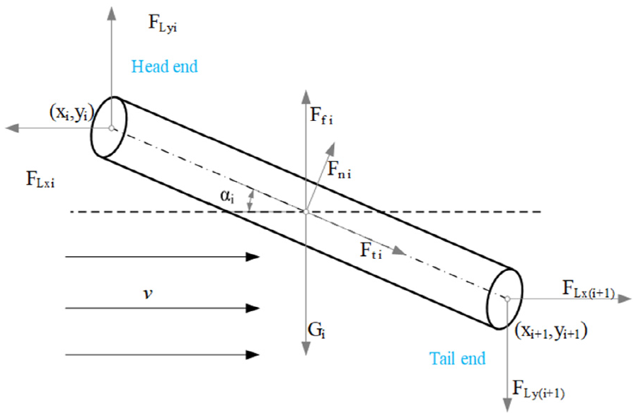
Force model of the i-th section rod.
Force balance
Analyze the force of the theoretical model to obtain the force balance equation along the x and y axes.


Moment balance
Based on the force analysis of the theoretical model and relevant coordinate information, a moment balance analysis is conducted. The node of the head end of each segment of the rod is the moment origin. The moment balance equation is as follows:

Boundary condition
Two boundary conditions are defined at the towing point and at the tail of the array. The towing point is the fixed point (zero displacement) between the towing system and the tugboat. The tail endpoints of the array are free and unconstrained in water (zero force). The following four boundary conditions are obtained:


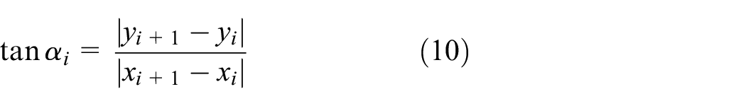
Geometric relation
The geometric relationship of the towing system is analyzed. The following formulations are obtained by trigonometric functions and the Pythagorean theorem.


The expression of the force
The expressions of gravity and buoyancy are obtained according to the volume of each rod, such as in equations (12) and (13).
According to the basic formula of fluid resistance


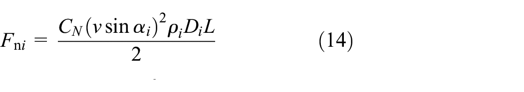

where:
Matrix assembling
The force balance equations (1) and (2), moment balance equation (3), and geometric relationship equation (11) are simultaneously combined. Thus, a set of nonlinear closed equation (16) can be obtained.
To solve the value of the equation, the iterative method is used to carry out the calculation. The maximum number of iterations is 3000, and the accuracy requirement is 0.001, when the solution process satisfies any of the above conditions, the iterative solution will be output as the final solution.

where


Drag coefficient
The drag coefficient value is significantly influenced by the density and size parameters of the towing system, tugboat speed, and water density. 31 In turn, the attitude of the underwater towing system is affected by changes in the drag coefficient.
Therefore, in order to ensure the calculation accuracy, this paper conducted several tests on the underwater towing system as shown in Figure 2, and obtained the calculation formula of the drag coefficient through data fitting.
The normal drag coefficient of the towing cable and the array is defined as

where:
The tangential drag coefficient of the array is defined as

where:
The tangential drag coefficient of the towing cable is defined as

where:
Results and analysis
In this section, the model and solution method of the underwater towing system are established, and the experimental data are fitted to establish the drag coefficient calculation formula. Several examples are used for analysis to verify the accuracy of both the modeling method and the drag coefficient calculated by equation (1). In addition, the factors affecting the attitude of the underwater towing system are analyzed, which provides an effective reference for the research of the depth control of this system.
Verification example
To validate the proposed modeling method and drag coefficient formula, two classical modeling approaches are selected for comparison. The first case (Reference 27) represents a continuous model solved by finite difference discretization, 27 while the second case (Reference 33) follows the principles of the lumped mass method under steady-state conditions. 33 These cases together cover the major modeling categories for underwater towing systems.
The proposed model and the drag coefficient formula are validated in this section through two tests.
Classical I
Rispin experiment (Reference 27) conducted by David Taylor Model Basin is used in this example.
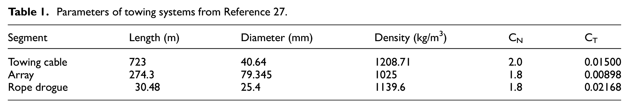
Figure 5 shows the simplified model of the Rispin experiment. Table 1 shows the parameters of the underwater towing system provided in Reference 27.

The towing model in the Rispin experiment.
Parameters of towing systems from Reference 27.
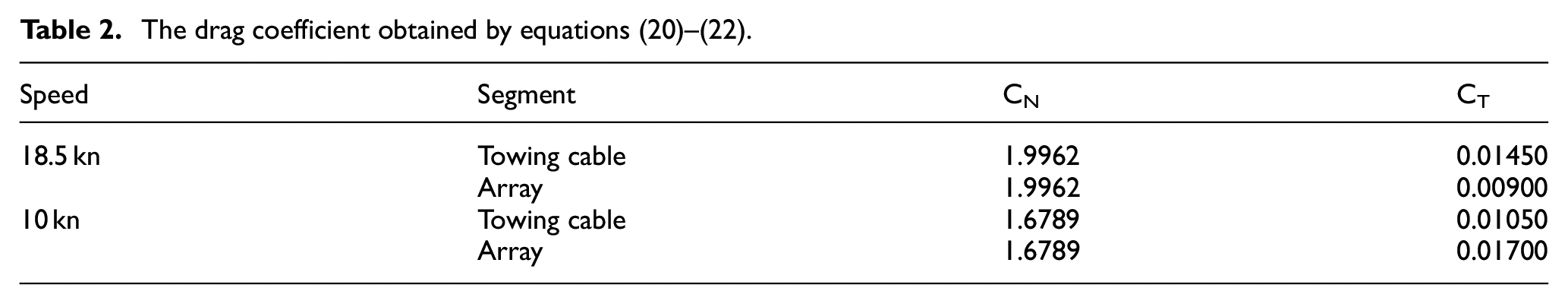
In this section, two speeds of 10 kn and 18.5 kn are selected for calculation. Table 2 presents the drag coefficient acquired through equations (20)–(22).
The drag coefficient obtained by equations (20)–(22).
The attitude of the underwater towing system is analyzed by calculation.
Figure 6 presents the attitude results of the towing system, while Figure 7 depicts the tension distribution results. The depth of the towing cable is 12.7 m (18.5 kn) and 28.9 m (10 kn), with a corresponding tension force of 93,000 N (18.5 kn) and 31,666 N (10 kn) at the towing point.

Attitude simulation results of underwater towing system at 10 kn and 18.5 kn speeds (Distance refers to the horizontal distance from the towing point.

Simulation results of the tension distribution of the underwater towing system at 10 kn and 18.5 kn. (The origin is the end position of the towing system. S is the distance from the end of the towing system).
According to the reference [27], the depth of the head end of the Array and the angle (between the first rod of the towing cable and the horizontal plane) are solved.
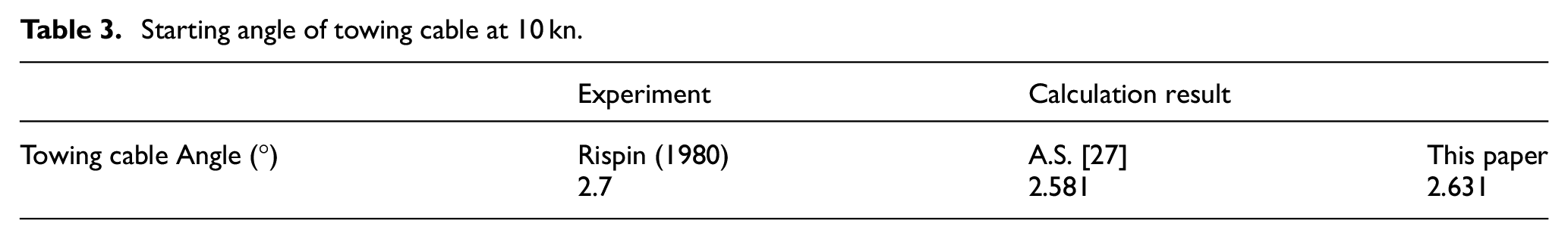
Tables 3 and 4 present a comparison of the results of this study with relevant experiments and reference. According to the data in the table, the calculated results in this paper are consistent with the experimental results at different speeds. The error is less than 4% at 10 kn and 10.7% at 18.5 kn, which is much lower than the calculation result in A.S. (Reference [27]).
Starting angle of towing cable at 10 kn.
The numerical calculation method employed in this model is comparatively straightforward, facilitating the rapid acquisition of numerical results in approximately 0.042 s via the computing platform utilized in this study (Frivolous notebook, AMD Ryzen 7 5700 U with Radeon graphics processor).
The results of the above study indicate that the model proposed in this paper can be employed to rapidly predict the attitude of underwater towing systems.
It should be noted that the 10.04-meter depth in Table 4 is based on the conditions from reference 27, used for model validation. The comparison here focuses on verifying the model’s performance at this depth. As the aim of this study is to validate the model with existing experimental results, this depth serves as a reference for initial verification. Further discussions on deeper depths, approaching 100 meters, are provided in the following sections.
Depth of towing array at 18.5 kn in direct navigation.

Classical II
This section utilizes data from Reference 33 to calculate the drag coefficient using equation (22). 33 Table 5 presents the towing system parameters in the reference. Table 6 displays the drag coefficient obtained by equations (20)–(22). The attitudes of the 2 , 3 and 4 m/s underwater towing system are calculated using the model developed in this paper. The calculated attitude and tension distribution results are compared with those in Reference 33.
Parameters of towing systems from reference 33.

The drag coefficient at each speed obtained by equations (20)–(22).

The attitude calculation results for the underwater towing system are presented in Figure 8, while the tension calculation results are shown in Figure 9.

Attitude simulation results of underwater towing system in this paper at different (the towing system parameters from Reference 33).

Tension distribution simulation result of underwater towing system by this paper at different speeds (the towing system parameters from Reference 33).
The analysis of Figure 8 indicates that there is a minimal discrepancy between the attitude calculation results obtained by the model and those reported in related reference 33.
The findings related to Figure 9 demonstrate that the tension calculation outcomes from this model are generally consistent with those reported in the reference 33.
Based on the analysis of attitude and tension results in this example, it can be observed that there is little difference between the calculated outcomes presented in this paper and those documented in reference 33. This further validates the precision of both the model and drag coefficient formula proposed herein.
Attitude simulation analysis
During the design of the underwater towing system, the underwater towing system depth and the underwater towing system tension are two key performance indexes. These indicators depend on factors such as the length of the towing cable, speed, the density of the seawater and the density of the towing cable.
Then, we examine the steady-state motion in various scenarios utilizing the model established within this paper, while also conducting an analysis of the impact of diverse parameters.
The underwater towing system illustrated in Figure 2 is considered. The underwater towing system is comprised of two components: the towing cable and the array. The respective physical parameters of these components are presented in Table 7.
Towing system parameters.

The effect of speed
Three speeds (10, 8 and 6 kn) are selected for calculation to study the effect of speed on attitude and tension in a towing system. The resulting drag coefficients are shown in Table 8
The drag coefficient at each speed obtained by equations (20)–(22).

The attitude of underwater towing system at different speeds are shown in Figure 10, while Figure 11 shows the results of the tension distribution. These data indicate that cable shape and tension vary significantly with different towing speeds. The graphs show that as drag speed increases, tension rapidly rises while the depth of the towing system decreases.

The results of underwater towing attitude simulation at different speeds.

The results of underwater towing tension distribution simulation at different speeds.
The effect of towing cable length
This section investigates how variations in the length of a towing cable affect the depth and tension of the towing system. Specifically, Three towing cable lengths of 520, 500 and 480 m are set up. The drag coefficient results obtained through equations (20)–(22) are presented in Table 9.
The drag coefficient at each length obtained by equations (20)–(22).

The results of the underwater towing attitude simulation at different towing cable lengths are shown in Figure 12, while Figure 13 shows the results of the tension distribution. As can be seen from these figures, the depth of the underwater towing system increases with the length of the towing cable, but the tension distribution is the same.

The results of underwater towing attitude simulation at 8 kn with different towing cable lengths.
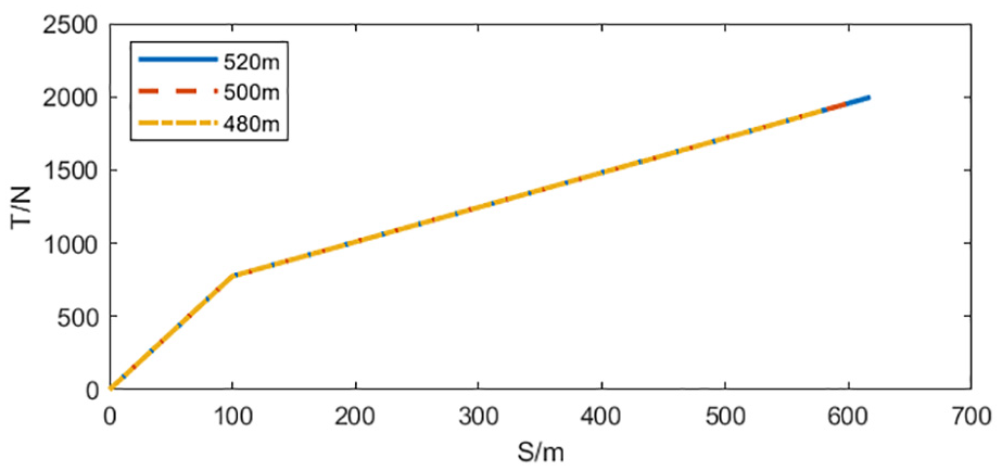
The results of underwater towing tension distribution simulation at 8 kn with different towing cable lengths.
The effect of seawater density
Due to the varying density of seawater in different sea areas, typically between 1020 and 1030 kg/m3, three densities of seawater 1028, 1025, and 1022 kg/m3 are selected for calculation. The results of the drag coefficient calculation are presented in Table 10, while Figures 14 and 15 show the outcomes of attitude simulation and tension calculations.
The drag coefficient at each fluid density obtained by equations (20)–(22).


The results of underwater towing attitude simulation at 8kn with different seawater densities.

The results of underwater towing tension distribution simulation at 8kn and different seawater densities.
From the results of Figures 14 and 15, It can be seen that the depth and tension of the towing system decrease as the density of seawater increases. However, the depth and tension of the underwater towing system do not change much as the fluid density remains relatively constant. Therefore, it can be concluded that the seawater density has minimal impact on the attitude and tension results of the underwater towing system when the density changes little.
The effect of towing cable density
Three towing cable density values of 1200, 1350 and 1500 kg/m3 are selected for the towing system attitude calculation. The results of the drag coefficient calculation are presented in Table 11, while Figures 16 and 17 show the results of attitude simulation and tension calculations.
The drag coefficient at each speed obtained by equations (20)–(22).


The results of underwater towing attitude simulation at 8kn with different towing cable densities.

The results of underwater towing tension distribution simulation at 8kn and different towing cable densities.
From the results of Figures 16 and 17, It can be seen that the depth of the underwater towing system increases with increasing towing density, but the tension distribution of the towing system remains essentially constant. Therefore, it can be assumed that when designing underwater towing systems, increasing the density of the towing cable is an effective means of increasing the depth of detection underwater.
Summary and robustness discussion
Through the simulation analyses conducted under varying towing speeds, towing cable lengths, seawater densities, and towing cable densities, it is observed that the developed model can accurately predict the underwater towing system’s attitude and tension distribution across a wide range of conditions.
Throughout all simulation cases, the iterative solution method consistently converged without any divergence or instability, thereby demonstrating strong numerical robustness.
This indicates that the proposed method is reliable and stable, making it suitable for practical applications in the design and operation of underwater towing systems.
Conclusion
In this paper, we fit the drag coefficient from experimental data and establish a model along with a discrete solution method for underwater towing systems, enabling rapid and accurate prediction. The model established in this paper is subsequently employed to analyze the influence of each parameter on the attitude of the towing system. Through the research, the following conclusions are obtained:
From a view of multi-segment rigid rods, this paper establishes a steady-state model of the underwater towing system in the form of nonlinear equations and gives the numerical solution of the model.
The model developed in this paper enables accurate prediction of attitude. Simulations of reported experiments in the reference using the present model achieved more accurate results compared to the simulation data in previous studies.
In this paper, the factors affecting the depth and tension of the underwater towing system are analyzed through calculation. It is concluded that the depth of the underwater towing system is directly proportional to the density and length and the towing cable and inversely proportional to the speed, the tension of the underwater towing system is directly proportional to the speed.
The research results and conclusions in this paper can provide a useful reference for the design of the towing system.
Footnotes
Handling Editor: Divyam Semwal
Funding
The author(s) received no financial support for the research, authorship, and/or publication of this article.
Declaration of conflicting interests
The author(s) declared no potential conflicts of interest with respect to the research, authorship, and/or publication of this article.