
Abstract
Cylindrical worms are sensitive to errors; mismatch can solve this problem. However, applying the finite element method to calculate the meshing characteristics of mismatched worm pairs has several limitations. Therefore, the meshing theory of mismatched ZN-type worm pairs is established using a numerical method. The contact equation of the mismatched ZN-type worm pair is solved numerically, and the error curves of the worm gear angle, transmission ratio, and worm gear angular velocity are obtained. The influence of different mismatched parameters on meshing conditions is studied, and the research results can guide how to configure different mismatched parameters. The results show that the mismatched ZN-type worm pair has a small transmission error, slight angular acceleration, stable operation, and good meshing characteristics. The numerical method has good reusability, which is more conducive to observing the influence of related factors on mismatch.
Keywords
Introduction
Characterized by their simple structure and broad industrial applicability, ZN-type worm pairs are commonly employed to transmit torque between spatially offset shafts. 1 The worm features a straight-sided normal tooth profile, manufactured using a straight-edged lathe tool to ensure geometric precision. 2
As a type of line-contact cylindrical worm drive, ZN-type worm pairs exhibit inherent sensitivity to various manufacturing and assembly errors. 3 In practical applications, however, unavoidable deviations from ideal geometry mean that theoretical line contact rarely fully materializes. 4 Converting nominal line contact to point contact has been identified as an effective solution to this challenge, 5 as it mitigates the detrimental effects of real-world imperfections on meshing performance.
Point contact is known to mitigate error sensitivity in worm gear drives. 6 During the meshing of a mismatched worm gear pair, the instantaneous contact point evolves into a contact ellipse under external load, with successive elliptical contact regions forming a continuous contact path. The geometric characteristics of this cumulative contact area ensure adequate load-carrying capacity by effectively distributing contact stresses, thereby balancing error tolerance and transmission performance.
Currently, the finite element method (FEM) is commonly employed for numerical calculations of tooth surface contact paths, yet it has inherent limitations. This approach is constrained by the accuracy of tooth surface modeling and is susceptible to external factors, leading to poor reusability; even under identical conditions, results may vary significantly. Moreover, its substantial computational workload hinders systematic investigations into the influences of relevant parameters. To address these issues, numerical calculations are instead conducted by establishing analytical expressions for tooth surface contact, offering a more controlled and efficient framework for such analyses.
To determine the contact area of mismatched ZN-type worm pair tooth surfaces, the worm tooth surface equation must first be established, followed by deriving the worm gear tooth surface equation using the meshing principle. Once the worm gear tooth surface equation is obtained, the system must satisfy the point-contact meshing condition, which serves as a constraint for formulating the governing system of equations. Typically, such systems are highly complex, incorporating numerous trigonometric functions that complicate the solution process. Direct computation often struggles to determine suitable initial values for the system, making it challenging to obtain convergent solutions. 7
Litvin et al. 8 proposed an approach to estimate meshing initial values by iteratively optimizing the closest points between gear surfaces and minimizing the deviation of their normal vectors relative to the contact surface. However, this method has practical limitations. The geometric construction elimination method 9 can reduce the number of parameters in the equations to one or a few, enabling more precise selection of initial values for iterative solution of the system. These initial values are then substituted back into the original equations to determine the solutions for all parameters. Once the parameters are solved, a series of checks are performed: verifying whether the datum point lies near the mid-region of the tooth surface, detecting any curvature interference on the tooth surfaces, confirming that the worm gear’s angular acceleration curve forms a downward-opening parabola with its vertex at zero, and assessing the overall rationality of the parameters. The mismatch parameters are then iteratively adjusted until all the above conditions are satisfied, ensuring the solution meets both geometric and kinematic requirements.
Litvin and Fuentes-Aznar 4 introduced the local synthesis approach, systematically analyzing various worm gear types and verifying that point contact exhibits lower error sensitivity compared to line contact in worm drives. Subsequently, Mu et al. 10 proposed further development of mismatching modification techniques in grid theory through physical information neural networks. Meng et al. 11 delved into the meshing theory of mismatched conical surface-enveloping conical worm pairs, deriving their tooth surface and meshing equations while establishing a systematic framework for point-conjugate gear transmission kinematics, from which kinematic error curves were obtained. Chi et al. 12 proposed a novel mismatched meshing worm drive mechanism and elucidated its meshing theory, expanding the practical applications of point-contact worm systems. These studies collectively advance the theoretical foundation and engineering applications of point-contact worm drives, highlighting their error-tolerant advantages and design flexibility.
Simon 13 proposed a new method for tooth contact analysis of mismatched spiral bevel gears, assuming that point contact under load extends into surface contact along the “potential” contact line. The influence of machine tool settings on tooth contact was also studied by minimizing the spacing function. Simon 14 studied the influence of cylindrical worm gear tooth errors and shaft misalignment on load tooth contact, developed a load tooth contact analysis method and computer program, explored contact lines, load distribution, transmission errors, and analyzed the effects of various factors.
When simulating tooth surface contact, understanding the curvatures of the two interacting surfaces and the dimensions of the contact ellipse is critical. This is primarily because tooth surface mismatch transforms idealized line contact into point contact, and the contact region near this point evolves into an ellipse under applied load. 15 Li et al. 16 proved that modifying parameters can affect the meshing performance of the transmission pair, thereby affecting the transmission performance. Liu et al. 17 analyzed point contact, line contact along tooth width, and line contact along tooth height, and the results showed that the contact form is the main factor affecting vibration amplitude and fluctuation.
Building on these foundations, this paper presents a computational analysis of the meshing theory for mismatched ZN-type worm pairs, employing numerical methods to conduct tooth surface contact analysis. The study systematically derives the computational formula for the relative principal curvature at the tooth surface contact points of such worm pairs. Through numerical simulations, key characteristics including the contact path, contact ellipse geometry, and kinematic error curve of mismatched ZN-type worm pairs are obtained, offering quantitative insights into their meshing behavior and contact mechanics.
The surface equation of the ZN-type worm pair and the hob
This section calculates the tooth surface equation when the worm gear and worm point are conjugate mesh. As shown in Figure 1, the worm tooth surface
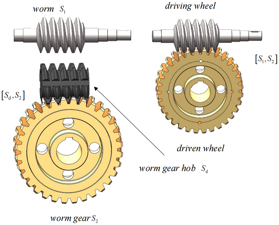
Meshing of mismatched ZN-type worm pairs.
Worm tooth surface equation
The tooth surface formation process of the ZN-type worm is shown in Figure 2. As stated in Zhao et al., 3 the tooth surface equation and unit normal vector of the ZN-type worm can be obtained as follows:

where

Schematic diagram of worm helical surface formation.
In the coordinate system

where

The second kind of fundamental quantity
3
of the surface

Establishing a moving unit orthogonal frame

From equations (2) and (4)

Since
According to differential geometry,
18
the mean curvature of
According to

where
Worm gear and worm gear hob tooth surface equation
Due to the similarity between the worm tooth surface and the worm gear hob tooth surface, the parameters of the worm gear hob can be obtained according to the worm calculation process. The tooth surface equation of the worm gear hob is

where
In the coordinate system


where
Similarly, the normal curvature and geodesic torsion can be derived as follows

The meshing coordinate system of the worm gear hob and the worm gear is illustrated in Figure 3. The angular velocity vector of the worm gear hob coincides with that of the worm gear, denoted as

Coordinate system of the worm gear grinding process with a hob.
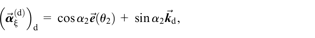
According to equation (8), the dynamic coordinate system

where
Similarly, the equation of the unit normal vector
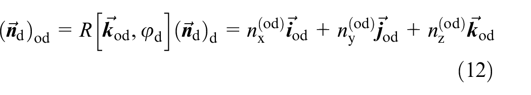
where
The relative speeds of the worm gear hob and worm gear are calculated according to the gear meshing principle
20

From equations (11) and (13), the relative velocity of the worm pair in the coordinate system

Using equations (12) and (14), the meshing equation is

where
After obtaining the meshing equation, it is necessary to convert the worm gear coordinate system to the coordinate system

By changing the coordinate of equation (16) and combining it with

This section calculates the worm and worm gear tooth surface equation and some fundamental quantities. The accurate calculation of the tooth surface equation of the worm gear and worm is the basis of subsequent calculations.
Mismatched ZN-type worm pair meshing equation solution
Transforming line contact into point contact is referred to as mismatch. This involves modifying the tooth surface of the original line contact gear pair so that it no longer satisfies the criteria for line contact but instead adheres to the local conjugate conditions for point contact. Consequently, the original line contact gear pair deviates from its initial meshing pattern, which is precisely what the term “mismatch” denotes.
To calculate the meshing principle of the mismatched ZN-type worm pair, several steps are required. First, the tooth surface equations of the worm and the worm gear must be expressed within the same coordinate system. Subsequently, the common-point condition, common-normal-line condition, and meshing equations of the worm gear and the worm gear hob are employed to formulate a system of equations. Finally, the elimination method is utilized to solve these equations.
Coordinate transformation of the worm gear and worm
The worm gear and worm meshing coordinate system is similar to the meshing of the worm gear and worm gear hob, as shown in Figure 4, where
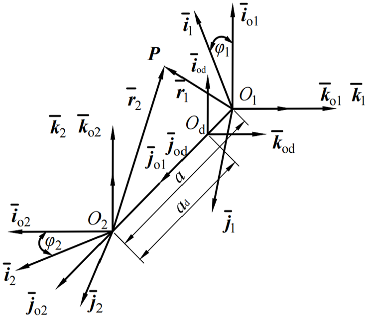
Worm gear and worm meshing coordinate system.
Transforming the worm equation into the coordinate system

The equation of the unit normal vector of the tooth surface of the worm in the coordinate system

In the coordinate system

where

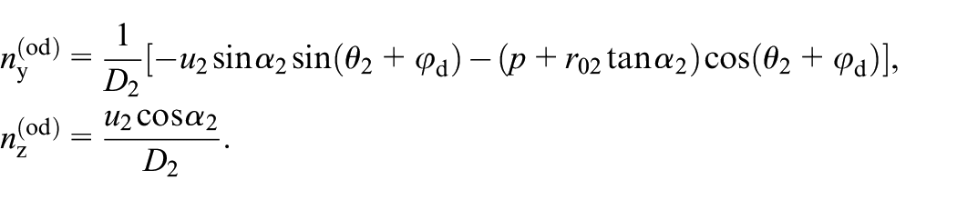
Similarly, the equation for the unit normal vector of the tooth surface of the worm in the coordinate system

where

Solution of the nonlinear equation
The instantaneous contact point shall meet the common point condition
Let


According to the conditions of common points, it can be obtained that


Using the meshing function

Equations (23)–(29) contain six independent equations and seven unknown quantities, which can be solved by the elimination method. Since the normal vectors of both surfaces are unit vectors, Equations (26)–(28) contains only two independent equations. The seven unknowns are
That is to say, the system of equations contains six independent equations and seven unknowns, which are eliminated until it becomes one equation containing two unknowns. Among them, only equation (28) contains the unknown variable
Step 1: Eliminate the unknown
After removing equation (28), the unknown

By introducing equation (30) into equation (27), in zdequation (27) can be eliminated to obtain the following equation

At this time, only equations (24) and (31) are left, including four independent equations and five unknowns
Step 2: Eliminate the unknown
Using equations (23) and (26), the following can be obtained

where
Similarly, according to equations (23) and (26), the following can be obtained

where
By using equations (32) and (33) to eliminate


where
In this case, equations (24), (34), and (35) contain four unknowns
Step 3: Eliminate the unknown
From equation (34),
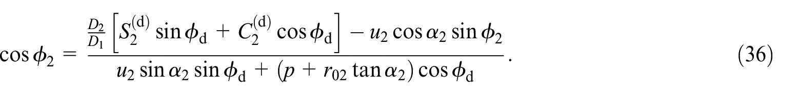
By using equation (36) to eliminate

From equations (24) and (34), it can be calculated as follows

Using the nature of the determinant, the calculation yields


where

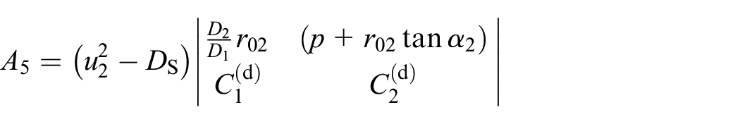
By substituting equation (39) into equation (37), the calculation yields

where


At this time, the equations (32) and (42) remain, which contain three unknowns,
Step 4: Eliminate the unknown
From equations (32) and (33), the following results can be obtained

The square of the two sides of the equal sign of equation (41) can eliminate the unknown

where
Square the two sides of equation (40) to obtain

where
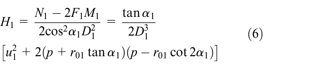
By applying the resultant elimination method to eliminate the unknown

When and only when
Datum point and intersection point of the contact path and worm pair boundary
When the worm gear and worm are engaged, the value of
Usually, a nonlinear equation of the point where the instantaneous transmission ratio error is zero is supplemented as the datum point of the conjugate tooth surface pair

From equations (21) to (26), it can be derived that:
When the instantaneous transmission ratio equals the nominal transmission ratio, the equation should be satisfied at the datum point is
From

By substituting equations (21)–(25) into equation (47), it can be derived that:

The relationship between the unknowns
Equation (49) is taken as the supplementary equation of the contact equations at the datum point.
When the datum point is determined, the contact path intersects with the worm top circle and the worm gear gorge circle. At the top circle of the worm
The third point is the contact path intersection and the worm gear’s gorge circle. The intersection of the contact path and the gorge circle must meet the following equation 3
that is
where
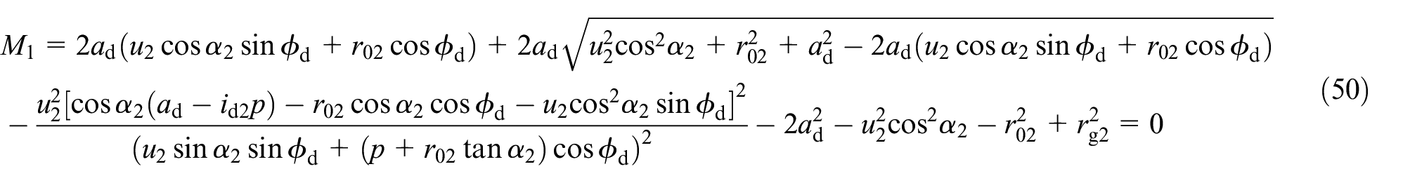
Equation (29) is used to obtain

By substituting equation (50) into equation (51) to obtain the relation between the unknowns
Previously, the datum and intersection points between the contact path and the root circle of the worm gear were determined. By constructing a line connecting these two points, the approximate location of the intersection between the contact path and the worm gear’s gorge circle can be preliminarily estimated. Using the datum point as the initial value in an iterative algorithm, the coordinates of the intersection point between the contact path and the gorge circle are solved. Once these three characteristic points are fully defined, all contact points along the path are derived through interpolation, forming a complete contact trajectory.
Kinematic error
Because the instantaneous transmission ratio is usually not equal to the nominal transmission ratio, the corner error and angular acceleration error of the driven wheel will increase. Except at the datum point, there is a transmission ratio error at every point, which is
Since the transmission ratio is not constant, there is also an error in the angle of the worm gear, and the error in the angle of the worm gear is
The worm gear angle error curve must be a parabola with a downwards opening to ensure good contact and reduce impact. Because the transmission ratio is not constant, there will also be errors in the angular velocity of the worm gear. The angular velocity error of the worm gear is
Calculation method for the long and short semiaxes of the contact ellipse
Relative principal curvature and relative principal direction of points on the contact path
Once the coordinates of each point on the contact path have been calculated, it must be ensured that all contact points are free from curvature interference.
After coordinate transformation, the following can be obtained:

where
According to the meshing principle, the normal vector of the contact path between the worm gear and the worm gear hob is

where

The curvature interference limit line function of the hob and worm gear is

The normal curvatures of the worm gear tooth surface along the

For the convenience of calculation, the unit orthogonal vectors on the worm gear and worm tooth surface are transformed into the same fixed coordinate system

As shown in Figure 5, the four-unit vectors at the contact point are in the same plane, and the angle


Contact ellipse at the instantaneous contact point.
The normal curvatures of the surface

In the directions

The induced normal curvature and induced geodesic torsion of tooth surfaces

According to equation (57), the relative mean curvature and the relative Gauss curvature at the contact point can be obtained

Then, the relative principal curvature can be expressed as

The normal vector of the worm is pointed from the gear surface to the inside, and if there is no curvature interference, the relative principal curvature
From the Euler formula and Bertrand formula,
where
Then the two main directions are
Half-axis calculation method for the contact ellipse
The worm gear and worm contact can be regarded as the contact between two isotropic uniform objects with different elastic constants. In the case of no curvature interference, after the two tooth surfaces contact at point

where
Results and discussion
Determination of mismatched parameters and contact path
Point contact analysis necessitates parameter adjustments based on line contact results, thus requiring parameter settings that ensure consistency and avoid mismatch. The primary geometric parameters of the worm mechanism are defined as follows: transmission ratio
The calculation results of the worm pair parameters.

The adjustable mismatch parameters primarily consist of the geometric design parameters for both the worm and the worm gear hob. According to the forming principle of the worm gear and worm gear hob, a straight line tangent to a cylinder with the radius of the guide cylinder spirally inclines around a fixed axis. Adjustments are made to specific parameters: namely, the geometric parameters
When setting the mismatched parameter, the datum point should be in the center of the tooth surface, and the resultant formula
Mismatch parameter selection.

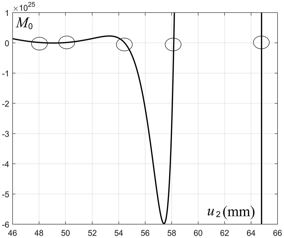
Image of
The calculation results of each point on the contact path and their relative principal curvature.

The calculation in section “Datum point and intersection point of the contact path and worm pair boundary” shows the intersection of the contact path and the worm gear top circle in Figure 7(a). When

The function image at the intersection of the contact path and worm gear boundary: (a) intersection of the contact path and the worm top circle and (b) the intersection of the contact path and worm gear gorge circle.
The complete contact path can be derived by assigning different values to the parameter
As depicted in Figure 8, the contact path is centrally positioned on the worm gear and extends across its tooth surface. The major axis of the contact ellipse is nearly perpendicular to the contact line, and the geometries of these ellipses vary systematically with different applied loads.

Contact path and contact ellipse of worm gear surface.
Kinematic error curves of the mismatched ZN-type worm pair
The computed angular error curves of the worm gear over three meshing cycles are illustrated in Figure 9. Each curve manifests a downward-opening parabolic profile, tangential to the horizontal axis at the datum reference point. Specifically, negative angular errors are observed at all non-datum contact points along the curves. A critical observation is the intersection of these curves across the three cycles, which quantitatively demonstrates that the contact ratio of the mismatched ZN-type worm gear pair exceeds unity. This geometric-mechanical characteristic enables continuous meshing transmission, ensuring overlapping tooth contact throughout the engagement period.
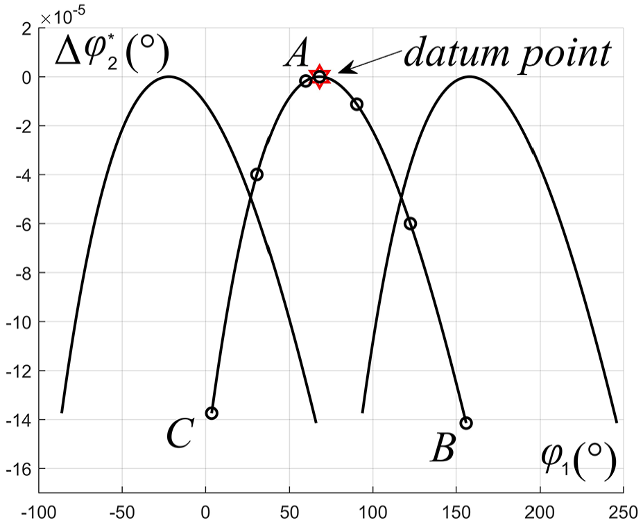
Worm gear angle error curve.
The transmission ratio error and worm gear angular velocity error profiles are presented in Figure 10. The transmission ratio error curve demonstrates a monotonic increasing trend, with its null point—where the theoretical and actual transmission ratios coincide—positioned symmetrically at the curve’s midpoint. Notably, the maximum value of this error satisfies

Kinematic error curve of the worm pair: (a) worm pair transmission ratio error curve and (b) worm gear angular velocity error curve.
Concurrently, the angular velocity error curve of the worm gear exhibits a low-magnitude characteristic, manifesting as a monotonically decreasing function throughout the meshing cycle. This behavior suggests that angular velocity deviations diminish as the contact point progresses from the entry to the exit of the meshing zone, likely due to the gradual alignment of tooth profiles and the distribution of contact stresses. The small order of magnitude, typically an order lower than the transmission ratio error, signifies that rotational speed fluctuations are effectively mitigated, which is essential for minimizing dynamic loads, torsional vibrations, and associated noise generation. Together, these error characteristics validate the design’s compliance with high-precision transmission requirements, where both kinematic accuracy and dynamic stability are paramount.
For ZN-type worm gear pairs with different degrees of diameter mismatch, the conclusions drawn are similar. When adjusting the mismatch parameters, it is necessary to ensure that the guide cylinder radius of the worm gear hob is slightly larger than that of the worm, that is,
Conclusion
This paper conducts a computational investigation into the meshing theory of geometrically mismatched ZN-type worm gear pairs. The analytical tooth surface equations for the worm and worm gear are systematically derived, followed by the establishment of contact equations specific to mismatched ZN-type configurations. The seven embedded unknowns within the contact equations are sequentially eliminated by employing the resultant elimination method, thereby reducing the system to a resultant matrix containing a single remaining variable. Numerical solutions are obtained for critical geometric features: the datum point, the intersection of the contact path with the worm gear’s gorge circle, and its intersection with the root circle. This numerical framework enables comprehensive parametric analyses with minimized computational effort during subsequent parameter adjustments, offering robust reusability for iterative design optimizations.
The mathematical formulation describing the relative principal curvature at the contact point is also rigorously deduced. Numerical simulations were conducted on the mismatching contact path and motion error curve of the ZN-type worm gear pair. The results show that the mismatched ZN-type worm gear pair exhibits excellent contact performance, a substantial contact area, and a well-defined motion error curve. Through minor adjustments to a few worm gear parameters, the mismatched worm and worm gear can achieve smooth meshing.
Footnotes
Handling Editor: Chenhui Liang
Funding
The author(s) disclosed receipt of the following financial support for the research, authorship, and/or publication of this article: This work was supported by the National Natural Science Foundation of China (52075083), the Fundamental Research Funds for the Central Universities (N25ZLL045), and the Open Fund of the Key Laboratory for Metallurgical Equipment and Control of Education Ministry in Wuhan University of Science and Technology (MECOF2022B04 and MECOF2023B01).
Declaration of conflicting interests
The author(s) declared no potential conflicts of interest with respect to the research, authorship, and/or publication of this article.