
Abstract
Humanoid robots feature a small support base and high flexibility; hydraulic humanoid robots provide additional advantages, including high power output and density. They exhibit significant application prospects in the service industry and specialized fields. This paper presents an innovative design methodology for the hydraulic humanoid robot HZ-1. During movement, the knee and hip pitch joints of the robot require significant power, and the effective dissipation of heat in the hydraulic oil is also crucial for maintaining stable operation of the hydraulic system. To address these challenges, a weighted multi-criteria optimization design method is proposed for knee and hip joint linkage mechanisms to enhance their power performance. Additionally, thigh plates and valve blocks in the leg structure with efficient passive heat dissipation capabilities are designed. A hydraulic pelvis is designed to make the robot more compact by integrating hydraulic circuits with mechanical structures. Finally, experiments involving squatting with a 100 kg load and stable walking are conducted.
Introduction
Humanoid robots are designed to resemble the human form, offering advantages such as compact support bases and high flexibility. These qualities make humanoid robot designs highly adaptable to regular human environments.1,2 They hold significant potential for applications in home services, education and healthcare, automated manufacturing, and disaster rescue.3–6
Humanoid robots can generally be categorized as motor-driven or hydraulic-driven. Motor-driven designs excel in control accuracy and energy efficiency, making them well-suited for precise operations.2,7 Hydraulic-driven designs, however, possess higher power density, greater output, and excellent shock resistance, making them ideal for heavy-load handling, rescue operations, and other high-intensity work environments.8,9
As an example, the Atlas robot developed by Boston Dynamics stands 1.5 m tall, weighs 89 kg, and can perform complex actions such as running, jumping, and backflipping—features which showcase exceptional potential of hydraulic-driven humanoid robots. 10 Hyon et al. designed a hydraulic humanoid robot capable of achieving fast joint torque control with a lightweight leg design that closely mimics the mass distribution of human legs. 11 Hydraulic wheeled-legged robots designed by Li et al.12,13 demonstrated the superior explosive power of hydraulic-driven joints through successful jumping experiments. Cho et al.’s 14 LIGHT robot design also performs exceptionally well based on an integrated hydraulic power unit. Despite these advances, there have been significantly fewer studies focusing on hydraulic-driven humanoid robots compared to those on motor-driven humanoid robots. Further, a great deal of design information on hydraulic humanoid robots remains undisclosed.
Hydraulic cylinders, when connected through a triple hinge or a four-bar linkage, can convert linear motion into rotational motion at joints. These linkage mechanisms are widely used in quadruped robots owing to their straightforward and compact structure.11,15,16 Many researchers have explored the optimization of such planar link mechanisms. For instance, Rhyu and Kwak 17 considered the tolerance of link dimensions and joint clearances in optimizing four-bar mechanisms. Gao et al. 18 applied motion planning to optimized the leg link mechanism of a jumping robot. Semini et al. 16 incorporated joint torque considerations when optimizing a hydraulic quadruped robot’s knee-joint four-bar mechanism. Khan et al. 19 improved the knee-joint link mechanism in a similar robot by drawing inspiration from the human knee joint. The four-bar linkage mechanism is also applied in the design of a humanoid robot hand. 20 However, few researchers have focused on improving the power performance of hydraulic joints by optimizing linkage mechanisms.
Based on existing hydraulic cylinder and electro-hydraulic servo valve models, the flow rate, maximum output, and peak power of hydraulic cylinders vary with speed.21,22 Moreover, at the same angular velocity, different linkage dimensions influence the cylinder’s speed and thereby affect the joint’s peak power. For humanoid robots, knee and hip pitch joints experience relatively high-power demands during fast walking and intense movements.23,24 Consequently, optimizing linkage mechanisms to enhance the power performance of these joints is meaningful.
The theoretical energy efficiency of hydraulic humanoid robots is capped at approximately 38%, with most of the energy dissipated as heat into the hydraulic oil. 11 Prolonged high temperatures in hydraulic oil can damage to hydraulic systems. 25 Currently, most hydraulic robots rely on heat exchangers to concentrate heat dissipation from the hydraulic oil.14,26–28 However, heat exchangers typically add considerable extra weight and volume, which is not ideal for devices that need to operate in confined spaces. Previous researchers have integrated heat dissipation structures into oil tanks to replace separate heat exchangers. 29 However, while this approach reduces weight and volume, the limited heat dissipation area of the oil tank tends to fall short of meeting the cooling requirements for hydraulic humanoid robots. Integrating cooling systems into the structural components of the robot can expand the heat dissipation area to effectively resolve this problem.
The contributions of this paper are summarized as follows:
(1) A weighted multi-criteria optimization design method is proposed for knee and hip joint linkage mechanisms to enhance their power performance.
(2) An efficient passive heat dissipation leg and a compact pelvis are designed with hydraulic oil circuits integrated into their structures, and a compact hydraulic-driven humanoid robot is developed.
The remainder of this paper is organized as follows. Section “Overview of the HZ-1 humanoid robot” presents an overview of the HZ-1 humanoid robot. Section “Design optimization of the linkage mechanisms for the knee and hip pitch joints to enhance joint power” describes the proposed optimization approach for knee and hip pitch joint linkage mechanisms to enhance joint power. Section “Mechanical design” presents the mechanical design of the robot incorporating this design. Heavy-load squatting and stable walking experiments are discussed in Section “Experiments.” Section “Conclusion and future work” provides a brief conclusion and outlines future work.
Overview of the HZ-1 humanoid robot
The HZ-1 hydraulic humanoid robot stands approximately 1.4 m tall, weighs around 74 kg, and features 12 degrees of freedom. Each leg has six degrees of freedom: three for the hip joint, one for the knee joint, and two for the ankle joint. Hip yaw joint is actuated via a gear-rack drive, while hip roll joint uses a direct rotary drive. The motion of the hip pitch joint and the knee joint is enabled by multi-linkage mechanisms, which convert the linear motion of the hydraulic cylinders into rotational movement at the joints. The linkage dimensions are as referenced in this paper. The pitch and roll movements of the ankle joints are achieved using two linear hydraulic cylinders in conjunction with a parallel mechanism. To enhance compactness and reduce the complexity of hydraulic circuits, some components are integrated into the robot’s structural frame.
Figure 1 shows the humanoid robot HZ-1, while Tables 1 and 2 present its main specifications and joint working ranges, respectively.

Humanoid robot HZ-1.
Main specification.

Joint working ranges.

Design optimization of the linkage mechanisms for the knee and hip pitch joints to enhance joint power
Walking is the primary movement mode for humanoid robots. During bipedal locomotion in humanoid robots, the supporting leg must maintain ground contact and counteract gravity when initiating a step, driven by the extension of hydraulic cylinders at the joints. Consequently, substantial power output is required at the knee joint and hip pitch joint of the supporting leg. As shown in Figure 2, this process involves extension of hydraulic cylinders. Hence, it is crucial to optimize the mechanisms of these joints to enhance power output characteristics during stepping movements. Research suggests optimal ranges of 15°–70° for knee flexion and −45° to 15° for hip pitch movement during walking.23,30 This part optimizes the linkage mechanisms to enhance the peak power performance of the knee and hip pitch joints during hydraulic cylinder extension within specific angle ranges, while maintaining motion ranges similar to those of humans. The knee joint has a range of motion from 0° to 130°, and the hip pitch joint has a range of motion from −100° to 20°.
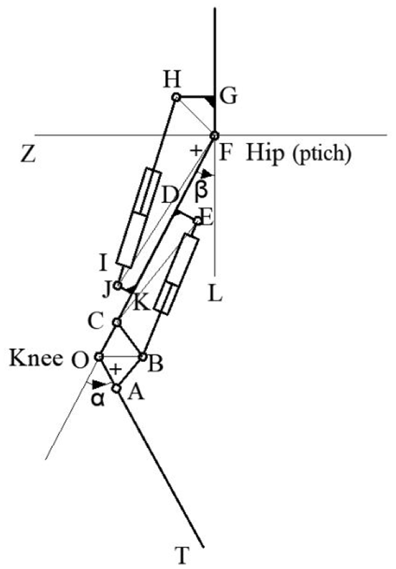
A linkage diagram of the knee and hip pitch joints.
Peak power of joints
Figure 2 shows a linkage mechanism diagram illustrating the movement of the humanoid robot’s knee and hip pitch joints, with each joint’s output power being determined by that of the corresponding hydraulic cylinder. The motion of the hydraulic cylinders in Figure 2 is achieved by controlling the voltage of the direct-drive electrohydraulic servo valves. Figure 3 presents a diagram depicting the extension of a hydraulic cylinder.
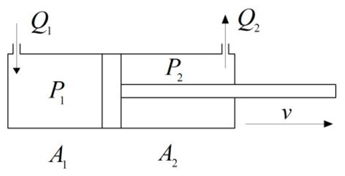
Hydraulic cylinder extension diagram.

The speed of a hydraulic cylinder is v.


The power (P) of a hydraulic cylinder can be expressed as follows:


Where

The knee joint and hip joint of the humanoid robot both utilize the same direct-drive electro hydraulic servo valve, which operates within an input voltage range of ±10 V. At an input voltage of 10 V, the maximum flow rate reaches 15 L/min under a working pressure of 21 MPa. So,

When u = 10 V and


The hydraulic cylinder operates at a working pressure of 21 MPa. When u = 10 V, the hydraulic cylinder can achieve its maximum power during the extension process. According to equations (1)–(4), (9), and (10), the expression for the peak power (

The relationship between the peak power (
Knee joint
The relationship between the peak power (
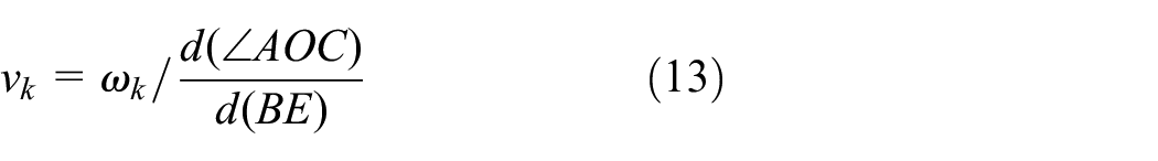
In the knee joint mechanism, the size of BE will vary as the hydraulic cylinder moves, thereby causing a change in the angle of the knee joint (
The angular velocity of the knee joint (

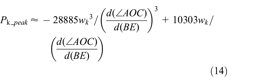
Therefore, the hydraulic cylinder velocity of the knee joint (
In the knee joint A1 = 4.9063e-04 m2, A2 = 3.7759e-04 m2. Based on equations (11) and (13), the peak power of the knee joint under various angular velocity (
Hip pitch joint
The relationship between the maximum power (
In the hip pitch joint mechanism, the size of HJ will vary as the hydraulic cylinder moves, thereby causing a change in the angle of the hip pitch joint (
The angular velocity of the hip pitch joint (
Therefore, the hydraulic cylinder velocity of the hip pitch joint (

In the hip pitch joint A1 = 3.14e-04 m2, A2 = 2.355e-04 m2. Based on equations (12) and (16), the peak power of the hip pitch joint under various angular velocity (

Design optimization method of linkage mechanisms
The joints’ linkage dimensions in Figure 2 are optimized using the Differential Evolution (DE) algorithm. Differential Evolution (DE) is a global optimization algorithm that primarily uses mutation, crossover, and selection operations to gradually find the optimal solution in the search space. 31 The algorithm is applied to intelligently search for the optimal solution in the linkage dimension optimization problem. In this study, we treat the linkage dimensions to be optimized as population individuals, setting the population size to 150. The iterative optimization proceeds through the following steps: first, new solutions are generated using differences between current population individuals (with a scaling factor set to 0.3); then, population individuals are mixed with a certain crossover probability; finally, a greedy strategy is employed to retain only superior solutions. This process continues for 2000 generations to ensure full convergence of the algorithm and output the optimal linkage dimension solution.
During the optimization process, a well-designed fitness function of the (DE) algorithm ensures that the link dimensions not only meet the required angular range for the joints but also enhance the power performance of the joints. The design method for the fitness function is as follows: if the link dimensions do not satisfy the geometric constraints, a significant penalty is assigned based on the degree of deviation; if the link dimensions meet the geometric constraints, a larger weight coefficient is assigned to the joint’s angular range, while a smaller weight coefficient is assigned to the joint’s power performance. The logic diagram of the fitness function design in the DE algorithm is shown in Figure 4.

Logic diagram of the fitness function.
Knee joint
The power performance of the knee joint shows enhancement within the 15° (0.2618 rad) to 70° (1.221 rad) flexion range, as this angular range matches the typical gait kinematics observed in both human and humanoid robot locomotion.23,30 By optimizing the linkage dimensions in linkage mechanisms of the knee joint, the peak output power within this range is improved, while preserving the overall movement range of 0°–130°. The optimized linkage dimensions include OA, OC, BC, AB, CD, and DE in Figure 2. The movement of the joint is caused by the movement of the hydraulic cylinder. BE represents the linkage dimension at the hydraulic cylinder, which changes as the hydraulic cylinder moves. The variation range is from 218 to 308 mm.
The value of the fitness function is determined by the maximum value
Calculation of
The unreasonable linkage dimensions at the knee joint can be categorized into two situations:
(1) Inability to form a proper triangle BCE;
(2) Ability to form a proper triangle BCE, but inability to form a proper triangle BAO.
When the triangle BCE is reasonable, the range of
Similarly, if it is not possible to form a proper triangle BAO, and the value of
Let
The lengths of CE and OB can be calculated based on the link dimensions. During the full stroke variation of BE, let the maximum value of
When a suitable triangle BCE cannot be formed, the weight coefficients


When a suitable triangle BCE can be formed (

When the link dimensions can form the corresponding link mechanism (
Calculation of
According to the motion law of the linkage mechanism at the knee joint, when the linkage BE is at its shortest, the knee joint angle α reaches its maximum value α1; while when the linkage BE is at its longest, the knee joint angle α reaches its minimum value α2. The expected values of α1 and α2 are 130° (2.2689 rad) and 0° (0 rad), respectively. The weighting coefficient

Calculation of
Humanoid robots experience a significant increase in power demand at the knee and hip joints during rapid walking, especially in quick transport and rapid search and rescue. To achieve high-speed movement, the angular velocity of these joints typically needs to reach or even exceed 6 rad/s. 23 Therefore, a joint angular velocity of 6 rad/s is selected to optimize the power characteristics of the joints.


When the link dimensions of the knee joint cannot form the corresponding link mechanism (situation 1), the fitness function is calculated as follows:

When the link dimensions of the knee joint can form the corresponding link mechanism (situation 2), the fitness function is calculated as follows:

Finally, the fitness function can be expressed as follows:

Hip pitch joint
The power performance of the hip pitch joint shows enhancement within the −45° (−0.7854 rad) to 15° (0.2618 rad) flexion range, as this angular range matches the typical gait kinematics observed in both human and humanoid robot locomotion.23,30 By optimizing the linkage dimensions of the hip pitch joint, the peak output power within this range is improved, while preserving the overall movement within the range of −100° to 20°. The optimized linkage dimensions include GH, FG, JK, and FK in Figure 2. The movement of the joint is caused by the movement of the hydraulic cylinder. HJ represents the linkage dimensions at the hydraulic cylinder, which changes as the hydraulic cylinder moves. The variation range is from 244.5 to 374.5 mm.
When optimizing the linkage dimensions of the hip pitch joint, the DE (Differential Evolution) algorithm is also employed. The fitness function design follows a similar approach to that used for the knee joint.
Result of joint linkage mechanisms
Table 3 presents the results of linkage dimension optimization for both the knee joint and the hip pitch joint, comparing the proposed method (considering joint power performance) with the case where only the range of joint motion angles is considered (without power optimization). The range of BE is from 218 to 308 mm and the range of HJ is from 244.5 to 374.5 mm. When only considering the range of joint motion angles, the value of
Linkage dimensions of the knee joint and hip pitch joint.

Figure 5 presents the peak power curves for the knee joint (15°–70°) and the hip pitch joint (−45° to 15°) when their angular velocity is 6 rad/s, both with and without considering joint power performance.
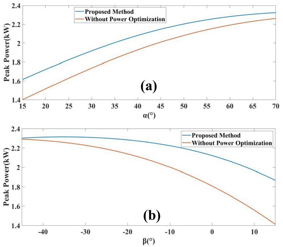
Peak power of the knee joint (a) and hip pitch joint (b) (
Table 4 also displays the average, maximum, and minimum values of the peak power curves for the case where
Power performance of the knee joint and hip pitch joint (

By applying the optimized link dimensions, the joints’ power performance has been enhanced across the entire range of angular velocities during a humanoid robot’s normal walking motion. As illustrated in Figure 6, for instance, at

Peak power of the knee joint (a) and hip pitch joint (b) (
The maximum stroke of the hydraulic cylinder at the knee joint is 90 mm, and the maximum stroke of the hydraulic cylinder at the hip pitch joint is 130 mm. The relationship between the hydraulic cylinder and the angle at the knee joint (a) and hip pitch joint (b) shows in Figure 7.

The relationship between the hydraulic cylinder and the angle in the knee joint (a) and hip pitch joint (b).
During running and traversing rugged terrain, the robot’s knee and hip joints operate within similar angular ranges as during normal walking. Within these motion ranges, the peak joint power significantly exceeds the power requirements for normal walking. Even at joint angular velocities reaching 6 rad/s, the average peak power at both joints exceeds 2 kW, demonstrating substantial dynamic performance margin in the joint actuation system. Consequently, the robot’s joint actuation capability not only satisfies conventional walking and squatting demands, but also reliably supports higher-dynamic motion modes such as high-speed running and complex terrain walking.
Mechanical design
Passive heat dissipation leg
Energy loss from throttling and internal leakage in electro-hydraulic servo valves generates significant heat during the humanoid robot’s movement. To address this, a passive heat dissipation design was implemented for the robot’s leg structure. Figure 8 illustrates the leg structure, which consists of the thigh, calf, linkage mechanism, and actuators at each joint. Heat dissipation in the leg primarily occurs passively through the thigh plate and the valve blocks on the actuators.

Leg structure.
The structure of the thigh plate and its heat dissipation analysis are shown in Figure 9. The thigh plate has been designed with a grid-style heat dissipation structure. The hydraulic oil circuit is integrated within the structure of the thigh plate, with the hydraulic oil port located on the plate. This port is connected to the oil port on the joint actuator via a hydraulic hose, supplying oil to the actuator. Under an ambient temperature of 20°C, the hydraulic oil undergoes a 45°C temperature increase, reaching 65°C. The heat dissipation analysis reveals that the thigh plate has a calculated dissipation power of 619.67 W. The heat dissipation performance of the thigh plate with grid design (a) is significantly better than that of the thigh plate without grid design (b), as shown in Figure 9. Therefore, integrating the oil circuit inside the thigh plate and designing the thigh plate in a grid pattern can effectively improve the heat dissipation performance of the leg.
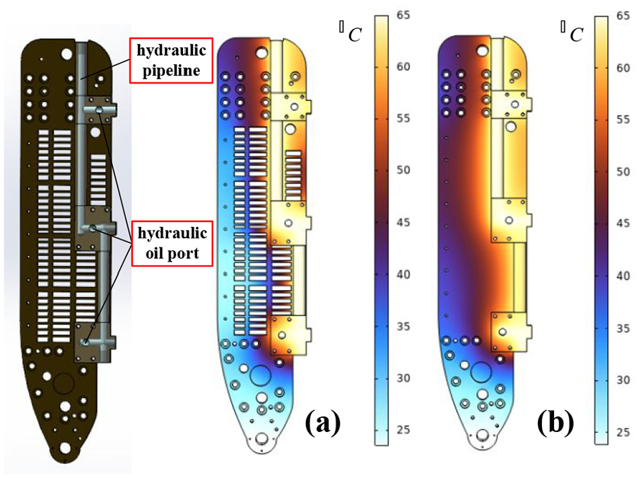
Heat dissipation of thigh plates with (a) and without (b) a grid-style heat dissipation structure.
Figure 10 shows the hip pitch joint actuator; similar actuators are used for the other joints. The actuator controls the movement of the hydraulic cylinder by regulating the flow through the electro-hydraulic servo valve. The hydraulic circuits are located within the valve block, connecting the servo valve to the hydraulic cylinder. Two pressure sensors are used to measure the pressure in both chambers of the hydraulic cylinder, enabling the calculation of the cylinder’s output force. Under an ambient temperature of 20°C, the hydraulic oil undergoes a 45°C temperature increase, reaching 65°C. Figure 11 demonstrates that the hip pitch valve block with heat sinks (a) exhibits significantly better heat dissipation performance than the version without heat sinks (b). The knee and ankle joint valve blocks also incorporate heat sinks.
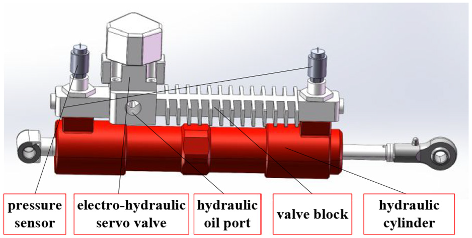
Hip pitch joint actuator.

Heat dissipation of hip pitch valve blocks with (a) and without (b) heat sinks.
Table 5 compares the heat dissipation power, total heat dissipation capacity, and total mass of the thigh plate and joint valve blocks between designs with and without heat dissipation features. The heat dissipation design reduces mass while increasing heat dissipation power by approximately 14.5% compared to the non-dissipation design.
Heat dissipation power and mass of single-leg heat dissipation structures.

In the leg structure, there are two thigh plates and four valve blocks. Among them, the knee joint and hip joint each have one valve block, while the ankle joint has two valve blocks. The HZ-1 hydraulic humanoid robot employs a passive cooling design, enabling prolonged continuous operation under normal ambient temperatures. The thermal management system delivers a heat dissipation capacity of approximately 4 kW under standard operating conditions (20°C ambient temperature with a 45°C temperature rise). Under steady-state conditions and based on the configuration of the Light hydraulic humanoid robot’s 3.3 kW hydraulic power unit, 14 the cooling system’s heat dissipation capacity surpasses the heat generated during the HZ-1 robot’s operation. This ensures that the hydraulic oil’s temperature rise relative to ambient temperature remains below 45°C, enabling reliable operation within the normal temperature range. This cooling design simplifies the leg structure by reducing piping requirements and eliminating the need for a separate heat exchanger, consequently decreasing the robot’s overall size and weight.
Compact pelvis
The pelvis forms the critical interface between the robot’s upper and lower body. By integrating hydraulic circuits within the pelvic structure, this design reduces external piping requirements and allows more flexible servo valve placement, enhancing overall compactness.
As shown in Figure 12, the movements of the two hip joints in yaw direction are driven by two identical gear-rack mechanisms, with the mechanisms located at the pelvis. In each transmission system, an electro-hydraulic servo valve controls the movement of the hydraulic cylinder. The hydraulic cylinder’s motion is controlled using angle sensor feedback, subsequently driving the gear-rack mechanism. The rotation angle of the gear corresponds to the rotation angle of the hip yaw joint.

Pelvis.
Figure 13 shows the internal oil circuit structure of the pelvic plate. The P port corresponds to the oil inlet of the electro-hydraulic servo valve, and its corresponding oil circuit is green; the T port corresponds to the oil return of the electro-hydraulic servo valve, and its corresponding oil circuit is orange; the A port corresponds to the rod-side chamber oil port of the hydraulic cylinder, and its corresponding oil circuit is yellow; the B port corresponds to the cap side chamber oil port of the hydraulic cylinder, and its corresponding oil circuit is purple. By controlling the electro-hydraulic servo valve, the flow rate and direction of oil at the A and B ports can be adjusted, thereby controlling the movement of the hydraulic cylinder. For example, when oil flows into the A port and out of the B port, the hydraulic cylinder will shorten; when oil flows into the B port and out of the A port, the hydraulic cylinder will extend. At the rear of the pelvic plate, there are three pairs of PT ports, with the middle pair connected to the hydraulic oil source, and the left and right pairs connected to the oil ports of the left and right legs, respectively.

Pelvis plate.
Experiments
The robot’s operating pressure is 21 MPa, and the experimental section demonstrates the robot’s heavy-load squat and stable walking experiments.
Figure 14 shows the robot carrying a 100 kg load. Figure 15 shows the knee joint’s angle tracking and torque during one squat cycle (using the right leg as an example), while Figure 16 shows the same for the hip pitch joint.

Squat (100 kg).

Angle tracking (a) and torque (b) of the knee joint during a squat motion.

Angle tracking (a) and torque (b) of the hip pitch joint during a squat motion.
Figure 17 shows the robot stable walking. Figure 18 shows the knee joint’s angle tracking and torque during one gait cycle (using the right leg as an example), while Figure 19 shows the same for the hip pitch joint.

Walk.

Angle tracking (a) and torque (b) of the knee joint during a walk motion.

Angle tracking and torque of the hip pitch joint during a walk motion.
Conclusion and future work
In this study, a compact hydraulic humanoid robot is designed. A weighted multi-criteria optimization method for linkage mechanisms enables the knee and hip pitch joints to achieve both required angle ranges and enhanced power performance within robot walking-specific operational ranges. The robot’s legs incorporate an efficient passive cooling system capable of dissipating approximately 4 kW of heat, effectively meeting the robot’s thermal management requirements. Additionally, integrating hydraulic circuits with structural components simplifies the layout of hydraulic hoses, creating a significantly more efficient arrangement and more compact pelvis design. Finally, angle tracking and joint torque data of the knee and hip pitch joints are collected during two tasks: squatting with a 100 kg load and stable walking.
In the future, we plan to: (1) refine the robot’s control algorithms to enhance motion performance, (2) design arms for heavy-duty tasks, and (3) apply thermally-coupled topology optimization to the leg structure to reduce weight while improving heat dissipation.
Footnotes
Handling Editor: Chenhui Liang
Funding
The author(s) disclosed receipt of the following financial support for the research, authorship, and/or publication of this article: This work was partially supported by the National Natural Science Foundation of China (No. 52188102) and Natural Science Foundation of Wuhan (No. 2024040701010037).
Declaration of conflicting interests
The author(s) declared no potential conflicts of interest with respect to the research, authorship, and/or publication of this article.