
Abstract
This paper deals with the development of a feedback control strategy on a SDoF (Single Degree of Freedom) absorber. It is desired to be resonant at two arbitrarily selected frequencies so that it suppresses vibration of primary system at these two frequencies. This problem has already been treated using time-delayed feedback control logic, which brings infinite dimensionality into the treatment. This paper offers a non-delayed feedback control logic with some additional benefits. It handles three facts of the problem: (a) the creation of a feedback logic to achieve resonance at two arbitrarily selected frequencies, (b) stability verification in real-time, (c) practical deployment of the control action. This method is applied to a single-mass primary structure. Two different tuning operations are considered: (i) for two precise and undamped resonances (ii) for two slightly-damped resonances. For both cases maps of stable operating frequencies are developed.
Keywords
Introduction
This paper presents a new control scheme to suppress oscillation on a multibody chain against excitation at multiple frequencies. The design still uses the broadly-accepted single mass absorber structure (i.e. single degree-of-freedom setups—SDoF) attached to the primary system by a spring and a damper. Such a passive absorber is known to be effective only for excitations around its most sensitive frequency.
This passive setting is supplemented by a new feedback control law using a single-mass absorber to be effective against time-varying multiple frequencies of excitation concurrently. In the literature various versions of this problem was handled earlier with the extended delayed resonator concept DR (Delayed Resonator) that implements a very simple force for the control within the absorber that contains an added delay. Such an operation, however, brings infinite dimensionality in the system with infinitely many poles. When the absorber is tuned to exhibit multiplicity of resonances (i.e. always purely imaginary characteristic roots) it behaves like an ideal vibration absorber at each one of those frequencies, and the suppression is accomplished. The stability of the overall system, however, becomes a complicated issue due to the delay-induced infinite dimensionality. Placing absorber poles on the imaginary axis at multiple frequencies creates an even more challenging task of assuring the asymptotic stability of the entire system. Due to this complication, the feedback law in this paper avoids the involvement of “feedback delay.”
First, we start with a review of the state of the art of actively—tuned vibration absorbers for single harmonic undamped excitation as well as the multiple frequency tasks including the time delayed treatment. We then present the novel idea in the paper.
We consider a Single Degree of Freedom vibration absorber consisting of a single mass
The main objective of this research is to tune a SDoF vibration absorber using a feedback control to be resonant at two arbitrary frequencies which agree with those of the excitation force. The practical demand for suppression of two or more frequencies even for single primary mass originates for example in cases of excitation by periodic but non-harmonic force which can be de-composed into dual harmonics.
Indeed, the periodic but non-harmonic excitation force can be replaced by excitation of multiple concurrent harmonic forces obtained by expansion of Fourier series of excitation periodic force.
In addition to the formation of the control logic, the stability of the tuned absorber deployment needs to be restored in real time. Another challenge is on the question how to implement the actuator feedback in a practical and simple way in cases for instance, when only the positions or accelerations are measured.
Vibration absorber is a powerful element that can suppress the oscillatory response of a system. Typically, it is an auxiliary mass attached to the system by a spring, damper and an actuation force element. Dynamic properties of such structures can also be actively controlled using actuators and sensors. The actuators are connected within a feedback loop and the main virtue of the controller is to better tune the absorbers to the excitation frequencies. 1 Such a tuned absorber could quiet the primary structure perfectly, if it is a “resonator” at the excitation frequencies (undamped tuning case). If the tuning is not perfect, the absorber exhibits “off resonance” behavior (i.e. exponentially decaying oscillatory impulse response). In such circumstances the primary system response would be somewhat attenuated (but not eliminated completely).
Guaranteed stability of the tuning operation is an important feature and it needs to be taken into account at the design stage. There are various advanced analytical, numerical and experimental methods used to design an active vibration absorber depending on the complexity of the system, some methods use semi-active tuning to attenuate nonlinear vibration of a flexible arm based on internal resonance. 2 Patent 3 for instance, uses a vibration absorber unit mounted on the exterior housing of hydraulic drive.
The concept of tuned-mass-damper is used to control the vibration of a hanger by Li et al. 4 In another study an advanced numerical approach of higher order Homotopy Perturbation Method (HPM) is used for solving two degrees of freedom system assuming nonlinear conditions. 5 Another nonlinear approach consists of rotational inertial double-tuned mass damper, that can reduce the acceleration response of the floor in frequency detuning, and it exhibits a robust response compared to the traditional linear dampers. 6
For larger structures some practical application of control technique under realistic condition are recommended by Bruner et al. 7 They include acceleration feedback controller. In the absence of computational time delay and sensor/actuator dynamics, the controller can provide guaranteed stability limits for collocated actuators/sensors.
Some other approaches are using adaptive tuning of the absorber which is based on magnetorheological elastomer and that is designed as a smart device for automated tuning to the time varying harmonic disturbance force to reduce the undesirable vibration of the primary mass in the steady state. 8 In most cases, active vibration absorbers include damping. Some applications that include damping has some disadvantages due to precise tuning, and some uses undamped vibration absorbers to strengthen the vibration suppression effects and simplify nonlinear convergence algorithm in their simulations. 9 There are also considerable research activities on using time delay with feedback control for active vibration absorption. The first concept of active vibration absorption was proposed in early 90s. 10 This design procedure uses a control law which is derived from a time delayed feedback of the displacement of absorber mass. The aim is to fully subdue the dynamics of the primary structure. Fundamental theory of this concept has two main aspects; first suppressing dynamic response of the primary mass perfectly for a wide frequency range and next to achieve the tuning of the absorber in real time.
Besides that many studies are devoted to vibration suppression, like Sun et al. 11
Extensive research progress has been made since then on the time delayed approach. A dual fixed frequency delayed resonator was considered by delayed position feedback, but the feedback imparts two resonances at two fixed frequencies.12,13 Such an absorber can be used to suppress the vibration against multiple frequency excitations. In recent years the idea was progressively developed yielding a novel strategy. 14
A recent study deals with an active control logic which consists of a control system design scheme that can handle multiple time-varying frequencies. 15 The key contribution of that effort is to increase the spectral sensitivity to the absorber at multiple frequencies. The tuning is achieved using new extension to the conventional method of delayed resonator concept with several delays. In this paper the method used can fully track all frequencies in real time. Feedback gains are verified in real-time. On the other hand, there are also some researches that aims at the difficulties of insufficient vibration isolation due to the time delay in feedback as in Wang et al. 16 Therefore the authors introduce a ground-based feedforward active control to tackle the problem and despite the inaccuracies in the feedforward segment the techniques suppresses the vibration.
The main concern in active vibration control is the unforeseen time delay that will reduce the performance especially when the system undergoes friction induced vibration, that may even cause vibration instability.17–20 The author smartly introduces a strategy to accumulate the critical time delay.
Another approach is described in Filipovic and Schroder. 21 It uses feedback based on lead/lag compensator scheme the gains of which are however difficult to be determined.
In this study a very simple strategy is developed for dual undamped frequency vibration suppression, with a real-time tuning procedure including the stability analysis. It is designed such that two undamped and off-undamped resonances are achieved in the absorber. In other words, the absorber substructure contains characteristic poles which tend to on or close to the imaginary axis. Therefore, the problem simply reduces to a pole placement.
The suppression in the primary system happens when the excited frequency coincides with sensitive frequencies of the absorber, while the absorber displays an oscillation.
This technique is an extension to both delayed resonator, 10 with single and multiple frequencies. 12 In summary this paper has created three kinds of feedback logic to achieve resonance at two specific frequencies without time-delay feedback, thus leading to only polynomial characteristic equation, this is ensuring to check the stability through real-time verification, and has provided the guidelines for implementation the control action practically. The method is applied to a single-mass primary structure and considers two cases of tuning: (i) undamped resonances and (ii) slightly-damped resonances. Stability maps and examples of time behavior of vibration suppression for both cases are developed to demonstrate the results.
The article begins with a comprehensive literature review and state of the art. It then represents dynamic model including design of dual frequency absorber, followed by comments on the future experimental studies. Next, this paper examines numerical simulations, before concluding with a summary of the implication of the research.
Dynamic model
The primary system is a SDoF system with mass


Primary system
Dual frequency vibration absorber
In order to create perfect dual frequency suppressions, the absorber needs to be resonant at these two frequencies

that uses twice integration. Notice that the designed vibration absorber with equations (1) and (3) together with the primary system (2) must be stable in some ranges of frequencies including ω1, ω2. The feedback formulation (3) leads to polynomial characteristic equations with finite number of poles that simplifies the analysis of stability compared with delayed feedback having infinite number of poles.
From the experimental concerns it is critical to consider whether the position

It is the second proposition of control feedback.
The vibration absorber synthesis using (3) as feedback law is described by Laplace transform

where capital letters of symbols correspond to Laplace transform L() of particular variables

Then the dynamic equation of vibration absorber (5) can be described as

The characteristic equation of the absorber subsection in (7) is


Besides these two propositions for feedback laws the third proposition for suitable feedback law described using Laplace transform is following

This feedback law is inspired by Pade approximation of delayed feedback used for delayed resonator.15,18 Pade approximation keeps the properties of delayed feedback but the resulting characteristic equation is polynomial one with finite number of poles. This again significantly simplifies the analysis of stability. The gains

Then the dynamic equation of vibration absorber (1) can be described as

And the characteristic equation of the vibration absorber in (12) is polynomial equation

In order to gain dual frequency vibration absorber, it is necessary to consider the effect of precise tuning and stability. For precise tuning and stability, two approaches are considered: Damped and Undamped vibration absorber is proposed.
Damped vibration absorber
Undamped vibration absorber is the main goal, but damped vibration absorber is described first because the derived formulas are general ones and include also the simplified version for undamped vibration absorber described later. Damped vibration absorber approach aims at placing two complex conjugate poles of the system with very small real parts of

Such vibration absorber is not perfect but it damps the vibration around the desired frequencies

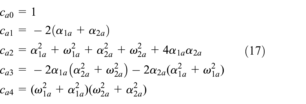
Thus, the coefficients of the characteristic equation of the designed vibration absorber are
In case of integral feedback (3) comparing (9) and (16), (17) the placement of frequencies into vibration absorber is

In case of feedback by Pade approximation (10) comparing (14), (16) and (17) the placement of frequencies into vibration absorber is

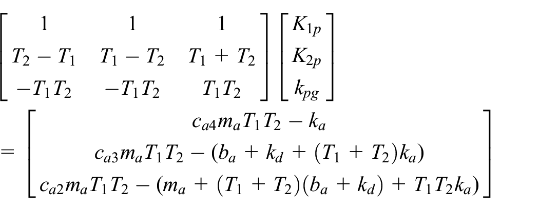
It is a general solution (18) for integration feedback and (19) for feedback by Pade approximation. This is full feedback for absorber with nonzero
Undamped vibration absorber
Undamped vibration absorber aims at placing two conjugate poles exactly at imaginary axis leading to perfect vibration suppression. In our application, it is required to achieve undamped vibration absorber where the vibration suppression is perfect. So, it must have two conjugate couples of poles on imaginary axis

Then

In fact,
For feedback by Pade approximation the equation (19) are only a little simpler with
This undamped vibration absorber is again a full feedback for absorber with zero
Stabilization of overall system
Because of stability of undamped vibration absorber the improvement of stabilization of overall combined system by the following partial feedback is proposed for integral feedback
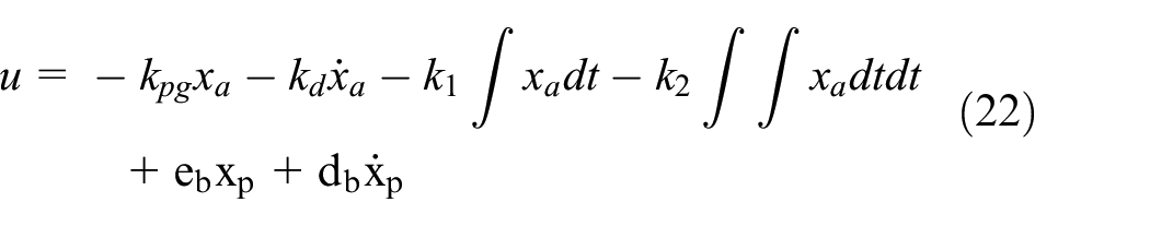
and for feedback by Pade approximation where for simplicity the feedback is described in Laplace transform
They are partial feedbacks because the four gains
Again, an alternative approach for second feedback proposition is the primary system stabilization by differentiation feedback (second feedback proposition) in case of acceleration measurement.
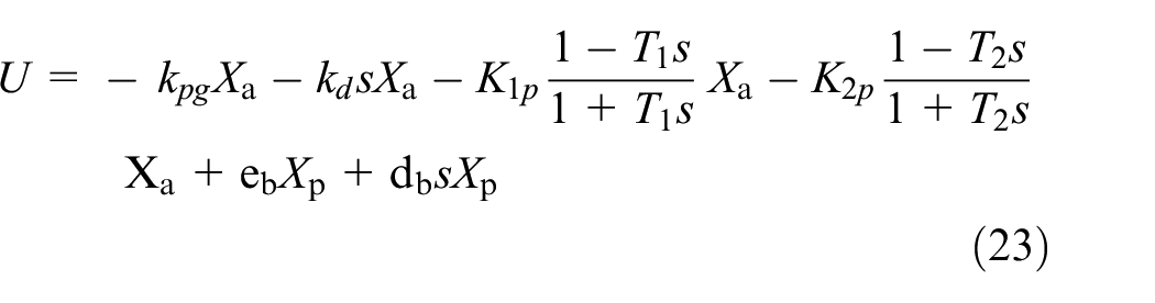
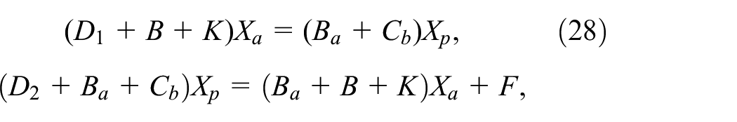
The problem of stability of overall system can be again advantageously described by Laplace transform. The designed vibration absorber including the primary mass with the feedback (22) are from (1) and (2)


where,

The equations (25) and (26) can be written
The characteristic equation of the vibration absorber remains the same as in (8). And the characteristic equation of the overall system is

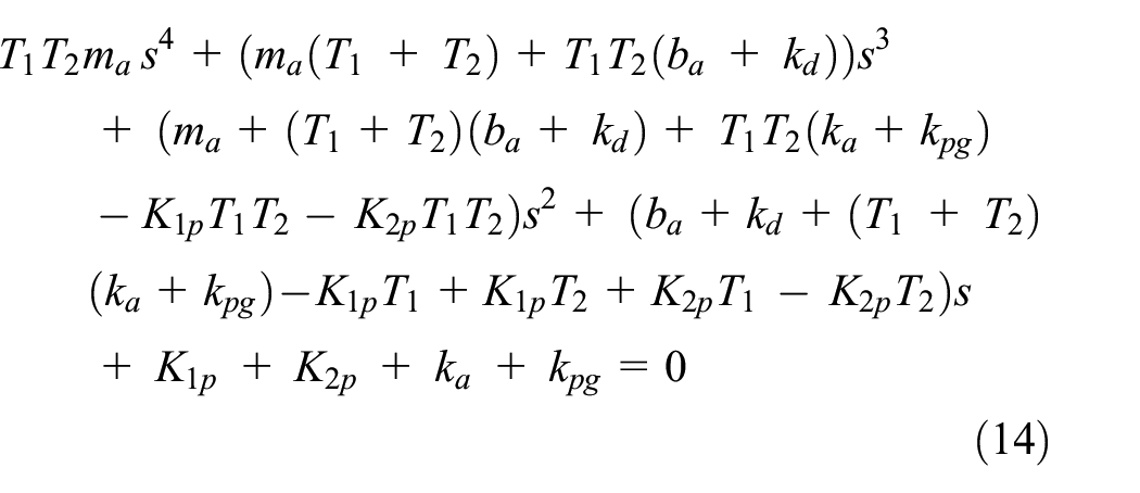
After simplification of (29) the characteristic equation of the overall system is

For integration feedback the resulting characteristics equation of overall system is

The problem of stabilization of overall system is that the feedback gains
And for feedback by Pade approximation after applying (23) and (11) in (1) and (2) the resulting characteristics equation of overall system is

The problem of stabilization of overall system is again that the feedback gains
To tackle the problem, in both cases of undamped and damped vibration absorber we propose some gain values to stabilize the system. For damped we prescribe gains (
So, to sum up, for damped case we have eight gains, four of them are from the damped absorber and four others are given equal to zero. And for the undamped case four gains are form the undamped absorber and the two of them are prescribed as an approximate with two others equal to zero.
Comments from the future experimental prospective point of view
It is always challenging to correlate the numerical and experimental measurement. In this paragraph we would like to point out the consequences and feedbacks of proposed vibration absorber from the experimental point of view. It is important to consider what must be measured. In principle there are three options. First option is to measure the bellow terms.

Second option is to measure the position of absorber including difference between positions of primary and absorber mass.

Third option is to measure the position and velocity of primary mass including the difference between primary and absorber mass.

The transformation between the feedback terms and gains g is in the bellow.

This means that the measurements (33)–(35) and based on them the feedback terms can be interchanged.
The measurement of any position
The other comment is about the implementation of Pade approximation terms from equation (10).

This can be transformed into a differential equation

By the method of subsequent integration a new state variable

with the initial condition

Then by one time integration it is obtained the output equation
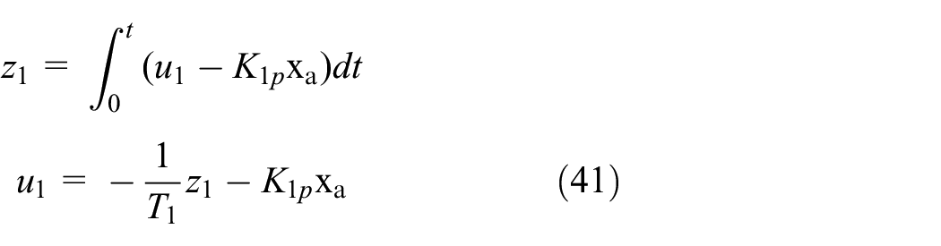
This means that for implementation of one Pade term (37) it is needed to integrate in time just one state equation (39) and use the algebraic output equation (41). Therefore despite of any number of Pade terms used in the feedback (10) the noise problems due to the chained time integration of measured variables of absorber and/or of primary system are not cumulated as in the case of integration feedback. This open the way for creating vibration absorber with any number of multiple excitation frequencies to be suppressed.
Numerical simulation
A set of numerical simulations are performed in order to verify the described approach and to investigate its properties. The primary system is excited by the force

where,
Physical parameters for numerical analysis.

Results of the numerical analysis are divided into two parts. The first part contains the dual frequency stability region plots and the second part consist of time behavior of vibration suppression of undamped and damped absorber.
To predict the exact couple of stable and unstable frequencies for undamped and damped vibration absorber design, it is essential to carry on an illustration. Therefore, the stability of the dual frequency vibration absorber using undamped and damped absorber are demonstrated using a mesh grid in bellow mapping plots as in Figure 2.
Damped integration feedback,
There have been carried out optimizations in order to achieve reasonable results in regions of absorber stability in frequency domain and simultaneously reasonable vibration attenuation in time domain. The results are the choice of
Frequency maps of absorber stability regions
In the below mapping, the stability of four different variants of absorber setting (undamped or damped mode, feedback kind by integration or Pade approximation) with suitable passive eigenfrequency and feedback stabilization gains on the region of excitation frequencies
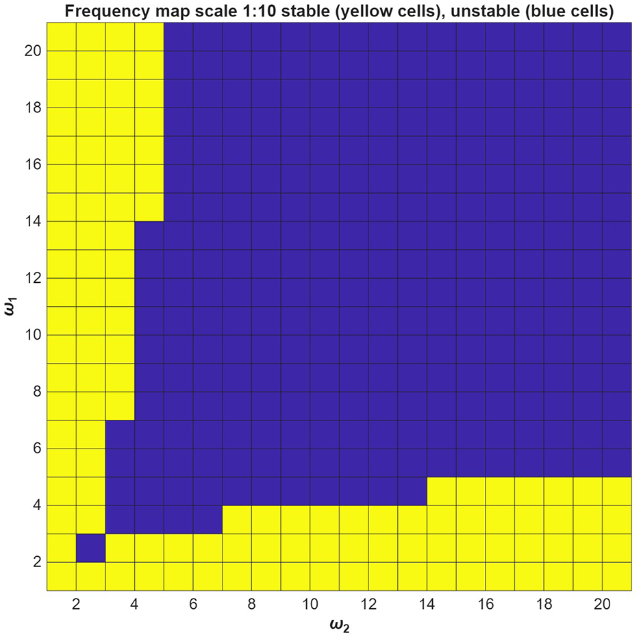
For each case the feedback gains according to (18), (19), (21) are computed and the stability of overall system (31), (32) is evaluated. The stable case is yellow, the unstable one blue.
Figures 2 to 10 illustrate the mapping of frequencies for stable zones shown in yellow pixels. The symmetric imaginary line in diagonal separates dual frequencies from (
Damped integration feedback
Undamped integration feedback with

Undamped integration feedback with

This plot shows damped vibration absorber with Pade feedback,

This plot shows damped vibration absorber with Pade feedback,

Undamped vibration absorber based on feedback by Pade approximation with

Undamped vibration absorber based on feedback by Pade approximation with

The plot shows frequency map of undamped vibration absorber based on feedback by Pade approximation with
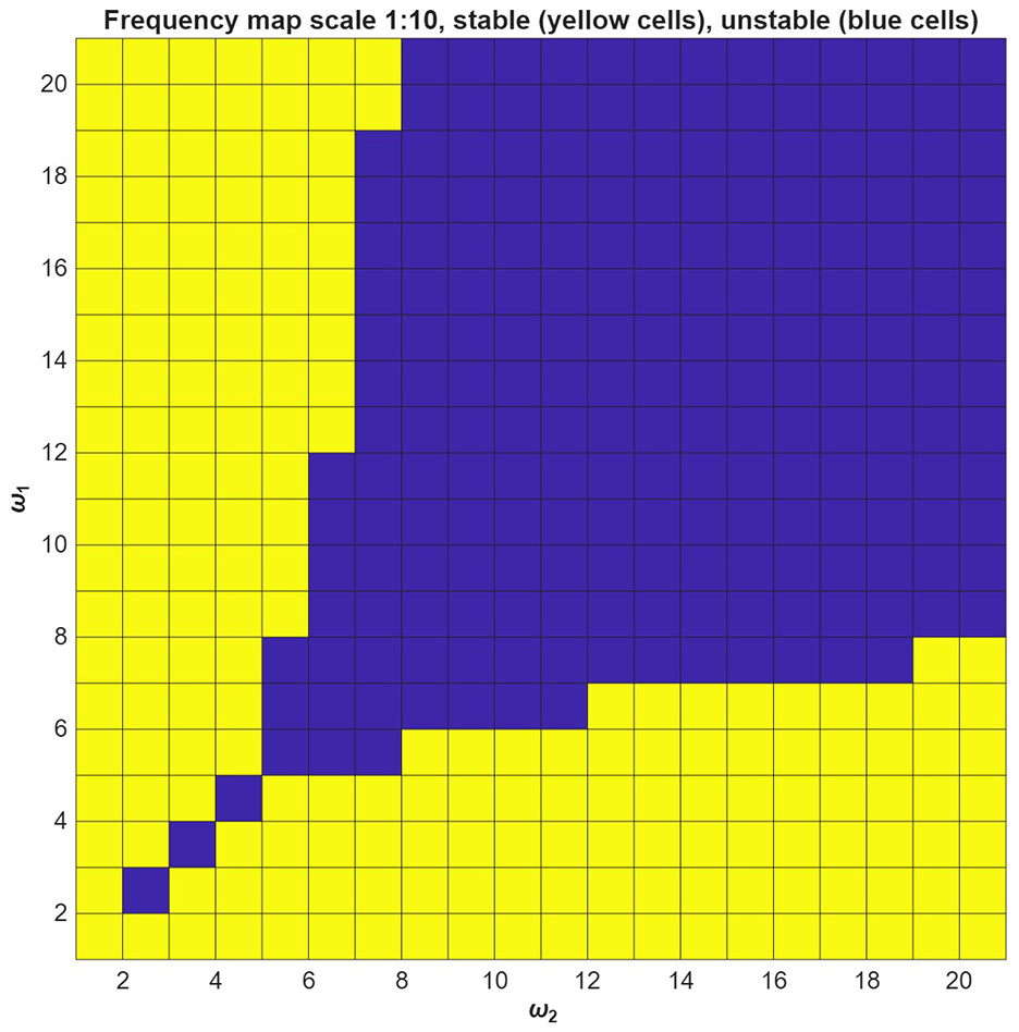
The first two mapping plots at Figures 2 and 3 show the stable regions for damped absorber with integration feedback. Figure 2 has an absorber with eigenfrequency
Figures 4 and 5 correspond to undamped absorber using the same integration feedback. In this case since there is zero damping assigned for the poles, it can be seen from the plots that the lower frequencies are getting unstable. It is good for med frequencies and less effective for higher frequencies. With having an absorber with lower eigenfrequency in Figure 5 there is a slight change with a couple of stable higher frequencies. Overall, both maps have almost similar stability regions.
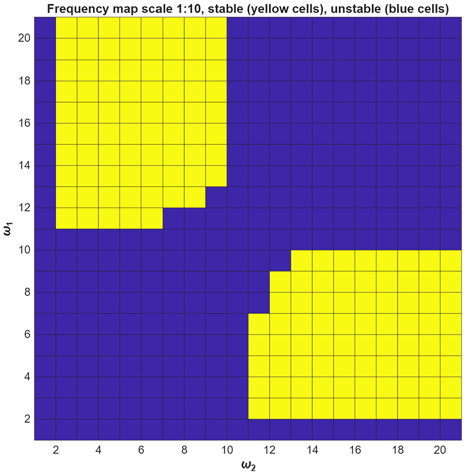
Figures 6 and 7 are plotted using Pade Approxi-mation feedback control. In this analysis selecting lower eigenfrequencies of absorber is less effective in stability since there is only one integration. Therefore, the eigenfrequencies of absorber is chosen to be higher, for instance in this case, at Figure 6 is chosen to be
Figures 8 and 9 demonstrate undamped vibration absorber using feedback by Pade approximation. It seems from the figures that there is 10% decrees in number stable regions for both plots with
Figure 10 is plotted for the undamped case of Pade Approximation with increased gains by doubled. The result is not satisfactory.
It was realized that the stability of vibration absorbers with integration feedback is improved by the choice of ωa < ωp and the stability of vibration absorber with feedback by Pade approximation by the choice of ωa > ωp. Such choices are already applied in Figures 2 to 10. Figure 10 demonstrates that the increase of stabilization gains e b , d b does not improve the stability region too much.
Time simulations of vibration suppression
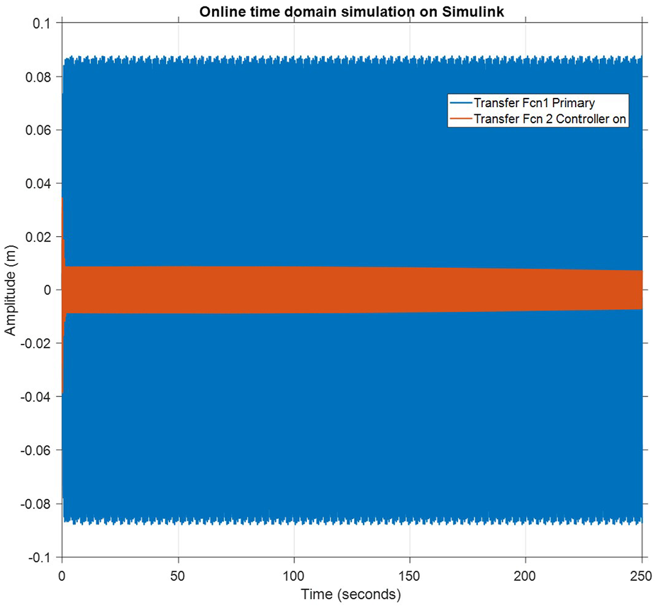
The stability of the absorber and overall system is plotted in the frequency maps, it is important to analyze the time simulation of each pair of maps for effective integration feedback and feedback by Pade approximation control laws. Time simulations are computed using Simulink. Figures 11 and 12 shows time domain response of damped vibration absorber using integration feedback with excitation of,
Damped vibration absorber based on integration feedback with excitation

Damped vibration absorber based on integration feedback with excitation
Figures 13 and 14 present the time response of undamped vibration absorber using integration feedback. The suppression is happening to the transient peak by a very slow time settling at around
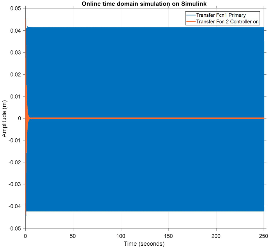
Undamped vibration absorber based on integration feedback with excitation
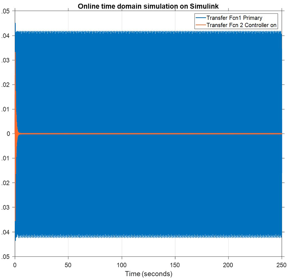
Undamped vibration absorber based on integration feedback with excitation
Figures 15 and 16 and Figures 17 and 18 represent the time domain analysis of the damped and undamped absorber respectively using feedback by Pade approximation. The time response at Figures 15 and 16 is for damped vibration absorber with excitation frequencies of

Damped vibration absorber based on Pade feedback, excitation

Damped vibration absorber based on Pade feedback, excitation
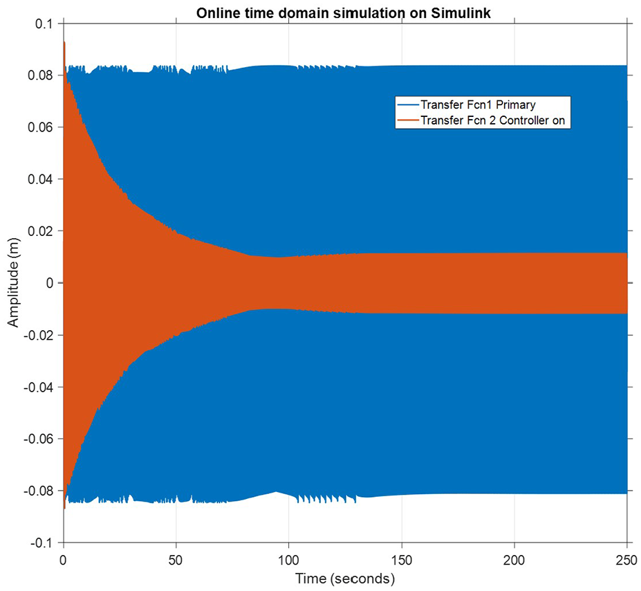
Undamped vibration absorber based on Pade feedback, excitation
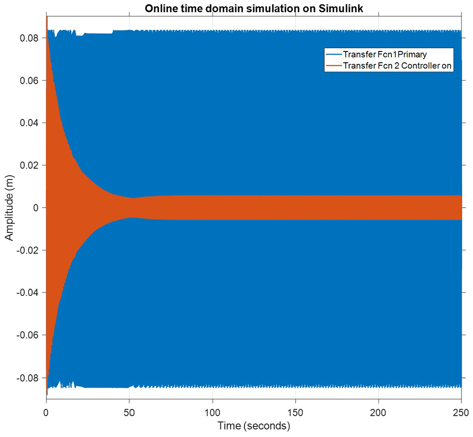
Undamped vibration absorber based on Pade feedback, excitation

Undamped vibration absorber feedback by Pade approximation, excitation

Damped vibration absorber feedback by integration, excitation
The multiple excitation frequencies could be suppress by multiple single frequency vibration absorbers. The investigated approach uses just one vibration absorber that reduces the added mass of absorbers. The feedback logic of integration or differentiation feedback compared to Pade approximation feedback logic is simpler and is resulting into simpler expressions of characteristic equation. This is an advantage. The disadvantage is that the integration or differentiation of noise can cause problems. The advantage of Pade approximation feedback is the need of just a single integration procedure of noisy signal per one Pade term. This advantage enables to consider the extension of Pade approximation feedback logic to really multiple (unlimited) number of excitation frequencies to be suppressed by vibration absorber.
This paper opens up the possibility to suppress the vibrations caused by nonlinear excitation as this can be expressed by Fourier series with multiple excitation frequencies that would be suppressed by the multifrequency absorber. This approach is fully feasible with the developed methods.
The proposed method could also act for vibration suppression of primary system with multiple degrees of freedom as the absorber can be resonant with all eigenfrequencies of such primary system that would be excited by some severe broadband excitation like shocks. This approach would require to develop efficient stabilization method of resulting dynamics. The on-going research seems to solve the stabilization of partial feedback of overall system that would enable to suppress vibration of multi-degree-of-freedom systems.
Conclusion
A simple integration feedback and feedback by Pade approximation is developed to suppress the vibration of SDoF system with excitation on multiple (here two) frequencies with just simple tuning. The advantage of this approach compared to delayed resonator is that stability of vibration absorber can be simply checked. Stability maps and vibration suppression time behaviors of the SDoF system are demonstrated using classical hand calculation, scripted in MATLAB and online time simulation using Simulink. Vibration suppression and simultaneously guaranteed stability map is improved using integration feedback law by simple tuning of absorber using undamped and damped absorber. Vibration suppression is even improved in larger level by using introduced stabilization gains.
Some questions in the implementation of integration feedback appeared and another feedback control law (feedback by Pade approximation) is developed to reduce the integration terms during the implementation. The advantage of using feedback by Pade approximation is that it uses only one integration instead of multiple chained integration used in integration feedback.
Further research activities are planned in this area, besides the experiments with real implementation attempts to solve the stabilization problem of partial feedback. Other research deals with vibration suppression of nonlinear excitation. The capability to suppress multiple frequencies simultaneously opens many new areas of vibration suppression. Nonlinear excitation and its influence on nonlinearity in systems leads to multiple harmonic excitation frequencies and the simultaneous vibration suppression of systems with multiple degrees of freedom.
Footnotes
Appendix
Handling Editor: Sharmili Pandian
Funding
The author(s) disclosed receipt of the following financial support for the research, authorship, and/or publication of this article: The numerical investigation is fully supported by the postdoctoral programme at the Faculty of mechanical engineering, Department of mechanics, biomechanics and mechatronics at the Czech Technical University in Prague.
Declaration of conflicting interests
The author(s) declared no potential conflicts of interest with respect to the research, authorship, and/or publication of this article.