
Abstract
The foundation soil will move under the action of ground building, which generates large additional stress on burial pipeline. If the stress exceeds the yield strength of pipeline, the pipeline will be destroyed. In order to analyze the influence of ground building on buried pipelines, theoretical and numerical method are used to analysis stress and deformation of pipeline. The research results show that ground building has a significant impact on the adjacent soil. The softer the soil is, the greater the internal stress within the soil will be. The effects of distance between pipeline and ground building on stress and deformation of pipelines are researched, and stress and deformation of pipelines subjected to the moving ground building are investigated. The analysis results have deeply understanding of ground building on the adjacent pipelines, and it has guiding significance for the construction of pipelines.
Introduction
With development of economy, more and more buildings are constructed on the ground. Because some builders have not find out the location of underground pipelines, and the construction of ground building has caused frequent oil and natural gas pipeline safety accidents, which not only has an effect on continuous supply to oil and natural gas users, but also causes great harm to safety and property of residents. 1 According to statistics, about 30% of pipeline accidents are caused by ground construction every year. 2 Pipelines is mostly burial depth within a few meters, and field laying is shown in Figure 1. Due to influence of ground building construction, original stress balance of soil is destroyed. The deformation of foundation will squeeze buried pipelines, and it will affect safe operation of pipelines if the deformation reaches a certain extent.

Pipe laying on site.
At present, there are many factors to pipe failure. Uneven settlement of foundation is the most important factor causing destruction of buried pipelines. 3 Especially for soft soil foundation, it is unstable, and the lateral deformation of foundation causes great additional stress to pipelines due to extrusion of ground building. If the additional stress of pipelines in one direction increases, the pipe will be crushed causing the pipe failure as shown in Figure 2.

Additional load of the ground causes pipeline failure.
Some scholars have done a lot of research on influence of external load on foundation. Goh et al. analyze influence of ground load on pile foundation by numerical analysis method. 4 Chai and Carter derived closed equation to calculate the lateral displacement causing by cement column installation based on cavity expansion theory, and proposed an empirical formula considering plane strain effect causing by single row piles. 5 These researches mainly focus on the influence of ground building on pile foundation, and the length of pile foundation is a range of depth, which is different with oil and natural gas pipeline.
Regarding research of pipe mechanics, little research has been done on the effects of ground building to pipelines. Guo and Wei use finite element method to analyze the transmission of semi-elliptical cracks inside pipeline. 6 Zhang et al. analyze the influence of explosion load on oil and natural gas pipeline, and the influence of explosion location and height on pipeline is analyzed. 7 Chattopaddhyay and Tomar based on the small strain finite element method of elastic-plastic materials, the ultimate load of weld between elbow and straight pipeline is given. 8 These researches focused on the impact of other loads on pipe, and it didn’t consider the impact of ground building construction on adjacent pipeline. Bęben and Steliga presented methods of prevention through the use of corrosion inhibitors in crude oil and natural gas transmission pipelines. 9 Badida et al. analyze the probability of pipeline failure by Fuzzy Fault Tree Analysis with expert elicitation. 10 These researches didn’t consider the influence law of soil deformation, and it didn’t analyze the relationship between pipeline deformation and the distance between pipeline and ground building.
In this research, the influence of ground building on adjacent soil is analyzed by theoretical and numerical method. The influence of ground building on the adjacent oil and natural gas pipeline is analyzed. The analysis of the influence of ground load on soil has a deeply understanding, and it has certain guiding significance for construction of pipeline laying.
Theoretical research of ground load to pipeline
The influence of ground building on pipeline is related to foundation soil properties, the shape of ground building section, and the distance of pipeline from stowage. In this analysis, it is assumed that the section shape of ground building is trapezoidal to analyze the influence of trapezoidal load on adjacent pipeline.
Soil displacement
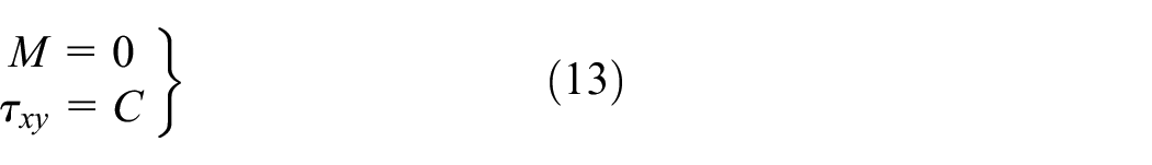
The soil material is elastic-plastic material, and there is cohesion and mutual friction inside soil. If the external load produces additional stress less than connection strength of soil, the soil only elastic deformation, and when the external stress is greater than connection strength of soil, the relative slip will occur, and the soil will be plastic deformation. In the plane analysis of soil, according to Mohr-Coulomb criterion, the limit condition that soil does not failure is as follows:

σ x = Horizontal additional stress, Pa;
c = Cohesion of soil, N;
ρ = Soil density, kg/m3;
h = Burial depth of soil, m;
g = Gravitational acceleration, kg m/s2;
φ = Internal friction angle of soil, °.
Taking a single soil unit as research subject, the force of soil unit on the plane is decomposes into vertical and horizontal direction. According to formula (1), the ultimate stress curve of soil can be drawn. According to Mohr-Coulomb criterion, if the Mohr circle of soil unit does not exceed the ultimate stress curve of soil, it is considered that the soil only undergoes elastic deformation. If Mohr circle is tangent to the ultimate stress curve, the soil will failure. The soil Mohr circle and ultimate stress curve are shown in Figure 3.

Mohr circle and ultimate stress curves of soil before and after loading.
Taking the whole foundation soil as the research subject, if the load section is trapezoidal, according to the theory proposed by Zeng, the lateral displacement of any point M(x, y, z) below the foundation can be obtained 11 :


The above dimension parameters are shown in Figure 4.

Influence of ground stowage on oil and gas pipeline.
Due to the influence of ground building, the foundation soil will generate additional stress and settlement deformation at any point. The additional load is transmitted to the pipeline through the foundation soil, and additional load and horizontal thrust are generated around the pipeline, and the pipeline generates additional stress and displacement. Due to the different displacements of soil and the unloaded soil the side of the ground building, the pipeline will produce a certain bending moment due to the displacement of foundation soil.
Soil stress around pipelines
Due to small cohesion and friction angle of soft soil, the soil is easy to move laterally under the ground building, which causes pipelines to move along with soil, and the additional load around pipelines increases. Assuming that the lateral compressive stress under the ground load on the foundation is P (P-including initial stress and additional stress caused by the ground building), the total lateral compressive stress at any point below the foundation can be expressed as follows:

In the vertical direction, the compressive stress of soil at any point can be expressed as follows:

Under the ground building, the vertical stress of pipeline is calculated by integrating the Boussinesq stress solution at any point in the foundation 12 :

Additional stress in horizontal direction:

Where,
According to the formulas (3), (4), (5), and (6), additional stresses of soil can be obtained in vertical and horizontal direction. Since most of buried pipeline are shallower and the ground plane belongs to free surface. If the additional stress is large in vertical direction, the extrusion will cause the pipeline to rise upwards. The horizontal additional load acts on the pipeline, and the pipeline will horizontal movement following with soil.
Pipeline mechanical model
The pipeline affected by the ground building is intercepted at the junction with other unaffected pipeline, and the mechanical analysis of the pipeline is carried out. The mechanical model of pipeline is shown in Figure 5. Additional load acting on pipeline is equivalent to the transverse uniform load q, and the shear force of pipeline end is Q. The bending moment is M, and the axial load is F (F is related to the influence length of the load disturbance pipeline and the friction coefficient between pipe and soil).

Mechanical model of the stowage acting on the pipeline.
The pipeline is equivalent to a longitudinally and transversely curved elastic foundation beam model subjected to axial force. According to the Winkle elastic foundation model, the deflection equation of pipeline can be obtained:
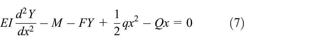
EI = Stiffness of pipeline;
q = Uniform load acting on pipeline, N;
Under the action of uniform load q, the pipeline will move laterally, and the axial force F will be generated in the axial direction of pipeline. The size of F is related to the length of pipeline and friction coefficient μ between pipe and soil. The mechanical model is shown in Figure 6.

Transverse additional load impact length.
According to the above mechanical model, the axial force is satisfied the continuity condition when affected and unaffected buried pipeline:

In equation (8), the disturbance length l of the pipeline under the influence of lateral additional load is unknown. The axial load at the contact position of the two pipeline segments is F, and as the distance from the load is further and further, and the axial force F is also getting smaller and smaller, and the axial force F tends to zero until the infinity. Obviously, the axial force F is a function of the length l of pipeline. In the analysis, the length l of the pipeline is divided into n segments, each segment is l/n, and the mechanical model for the length of micro-pipeline is equivalent to a longitudinally and transversely curved elastic foundation beam with lateral load and concentrated load at both ends. The mechanical model is shown in Figure 7.

Mechanical model of micro-length pipeline.
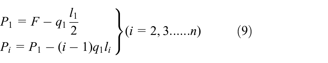
The friction between micro-pipeline and soil is equivalent to the concentrated force at both ends of pipeline, and the concentrated axial force of each micro-pipeline is as follows:
According to the Winkle foundation model, the deflection equation of the pipeline can be obtained:
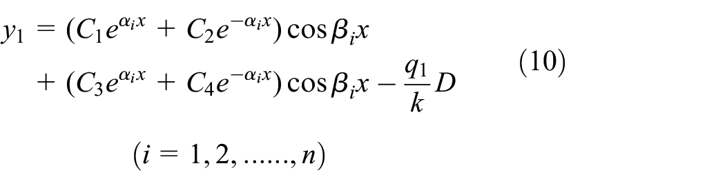
Where,
According to the continuity condition, the adjacent pipelines satisfy:

When the contact positions of the two pipelines of length l and length L satisfy the continuity condition, it can be obtained:

y = the deflection of pipeline length l, m;
Y = the deflection of pipeline length L, m.
Deflection theoretical solution of the pipeline can be obtained according to equations (7), (10), and boundary conditions. For the stress of the pipe section, the stress of the pipe section is analyzed by numerical analysis method because of the different stresses at different pipe section positions.
Numerical calculation model
According to the field engineering practice, the finite element analysis model of the influence of ground building on adjacent oil and gas pipelines is established by finite element method, and the model size is consistent with the field, as show in Figure 8. The author analyzes the influence of four different mesh sizes on numerical model, and the analysis results show that the error is 4.25% when the number of mesh is 690,000, which meets the allowable requirements of the project. The number of elements of 764,000 slow down the computation. Therefore, the calculation model elements number is 690,000.

Model size and element sensitivity analysis.
Selecting a construction site as an example, the numerical calculation method is used to analyze the impact of ground building on surrounding oil and gas pipeline. The distance between the center of pipeline and the edge of the ground building is 8 m, and the foundations are clay (2-2), soft soil (2-2-1), round gravel layer (2-4), and loose clay (4-3-2) respectively. The thickness of the formation is 3.1, 3.5, 3.5, 14.9 m respectively, and the distance from the top of the pipeline to ground surface is 3.15 m. Model size and section parameters are shown in Figure 9.

Section size of analysis model.
Through geological exploration, the material parameters of the formation can be obtained as shown in Table 1.
Formation material parameter.

There are three type of pipelines including product oil pipeline, crude oil pipeline, and natural gas pipeline. The diameters of the pipeline are 323, 813, and 1013 mm respectively. The pipe material is elastic-plastic material, and the pipe elastic modulus is E = 2.1e 11 , Poisson’s ratio μ = 0.3. The pipe steel grade adopts L360, X60, and X80 respectively. The pipe plasticity curve is shown in Figure 10.

Pipe stress strain curve.
The pipeline is divided into pressure pipeline and non-pressure pipeline, and the pressure and the non-pressure correspond to the pipeline operation and the rest state respectively. The designed internal pressures of product oil pipeline, crude oil pipeline, and natural gas pipeline are 15, 12, and 10 MPa respectively. The rectangular coordinate system is established with the ground plane as the XY plane and the Z axis direction perpendicular to the ground surface. The fixed constraint is adopted on the XY plane of the pipeline, and the pipeline can move freely in the Z direction. The boundary of the pipeline model is shown in Figure 11.

Pipeline model boundary.
The thickness of the foundation below the ground building is L y = 25 m, the ground building is filled with soil, the thickness of the filling is h1 = 9 m, and the building edge is treated with slope, and the slope angle is 30°. The numerical calculation model is shown in Figure 12.

Numerical analysis model.
In order to facilitate analysis, the influence of extreme cases on the model is not considered. Model assumptions:
(1) Isotropic elastic-plastic materials are used for pipelines and soils;
(2) The contact property between the pipe and the soil adopts limited slip, and the friction coefficient between the pipe and soil is 0.3 13 ;
(3) The stratum material is evenly distributed in the horizontal direction.
Analysis result
Pipeline mechanics model
Due to the influence of the ground building, the stress and the displacement of the foundation soil change, and the displacement vector diagram and stress cloud diagram of the foundation are shown in Figure 13.

Stress and displacement of foundation soil: (a) displacement vector (m) and (b) stress nephogram (MPa).
Due to the ground load extrusion, the soil in front of the ground building moves horizontally, and the soil under the building moves vertically. The maximum displacement of the soil below the building is 0.3 m, and the soil in front of the building moves laterally. The lateral displacement is 0.2 m. The stress under the ground building is the largest, and the maximum stress is 0.6 MPa.
Regardless the influence of the pipeline on the soil, the displacement curve of the soil with different distance from the ground building is analyzed as shown in Figure 14.
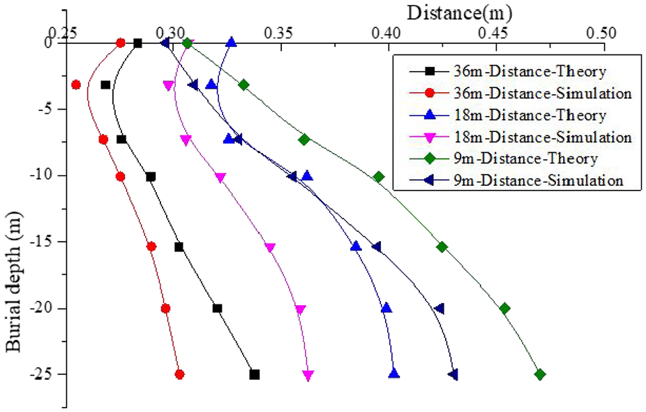
Displacement of soil at different distance from the stowage.
Through the analysis of the Figure 14, it is found that the closer the soil is to the ground building, the largest the soil displacement, and the most affected by the ground building. The displacement of the soil with buried depth range of 5–20 m is the largest, and the displacement of soil with depth 0–5 m and more than 20 m is less varied. The maximum error between numerical and theoretical results is 13.79%. Due to limitation of numerical calculation model, numerical calculation result is slightly smaller than theoretical calculation result, but the error is within the engineering allowable error range (<25%).
The soil stress with different buried depth is analyzed, and the equivalent stress of soil is considered. The equivalent stress is calculated, and the equivalent stress curves of soils with different distances from building and different buried depths can be obtained as shown in Figure 15.
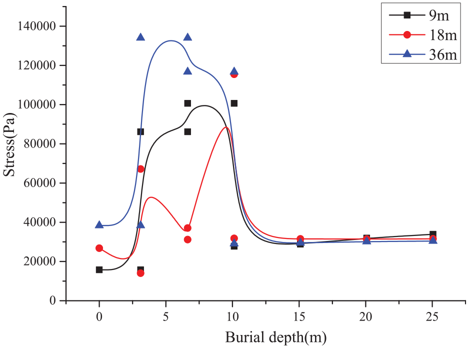
Different buried depth soil stress.
Through the curve analysis found that the equivalent stress of soil is the largest in the soft soil with depth range of 3–7 m. The soft soil stratum stress is obviously larger than other strata, and the stress of other stratum is relatively small. In the actual process of laying pipeline, the 3–7 m range is also the buried depth of pipeline. Therefore, the impact on the pipeline is the largest.
Pipeline displacement
During process of oil and gas transportation, pipeline transportation adopts pressure transportation. Under the action of ground building, the pipeline displacement curve is shown in Figure 16.

Displacement curve of pipeline.
Through curve analysis found that the displacement of the nearest product oil pipeline from the ground building is the largest, reaching 125 mm. The displacement of the natural gas pipeline farthest from the ground building is only 97.5 mm. The displacement of the crude oil pipeline is 115 mm.
Pipeline stress
As the ground building squeezes the foundation soil, the soil around the ground building moves laterally, generating larger additional stress in horizontal direction to pipeline. The stress curve of pipe section is shown in Figure 17.

Stress distribution of pipe section.
In the circumferential direction of the pipeline, the stresses of the pipeline are not much different in the initial state. Due to the influence of the additional stress to the pipeline, the horizontal stress of the pipeline becomes larger, but the stress in the vertical direction of the pipeline does not change much.
In actual project, it is more concerned with the average stress variation in the pipe axis direction due to influence of the ground building. Selecting a path along the axis of the pipeline to analyze the pipeline stress curve due to impact of the ground building. The stress curve of the pipeline before and after construction of the ground building is shown in Figure 18.

Stress curve of the pipeline before and after the construction of the stowage.
Through curve analysis found that the stress of crude oil pipeline is the largest, and the initial stress of crude oil pipeline reaches 302 MPa. The stress of crude oil pipeline reaches 320 MPa after the action of ground building. The initial stress of natural gas pipeline is 283 MPa, and the stress after ground building construction reaches 296 MPa. The product oil pipe has the least stress, and the initial state stress is 225 MPa, and the stress reaches 230 MPa after ground building.
Disturbance analysis from the pipeline
According to Figure 6, considering the influence of the lateral length L of the pipeline on the adjacent pipeline due to lateral movement, it is assumed that the length of the affected pipe is l, and the length of the pipeline l is related to the friction coefficient and the distance of the pipeline from the ground load. The pipe section at infinity far from the ground building satisfies:
In order to analyze the influence of pipeline movement on adjacent pipeline, a full-scale model of the influence of load on pipelines is established. The model considers the influence of load on adjacent pipeline. The numerical analysis model is shown in Figure 19.
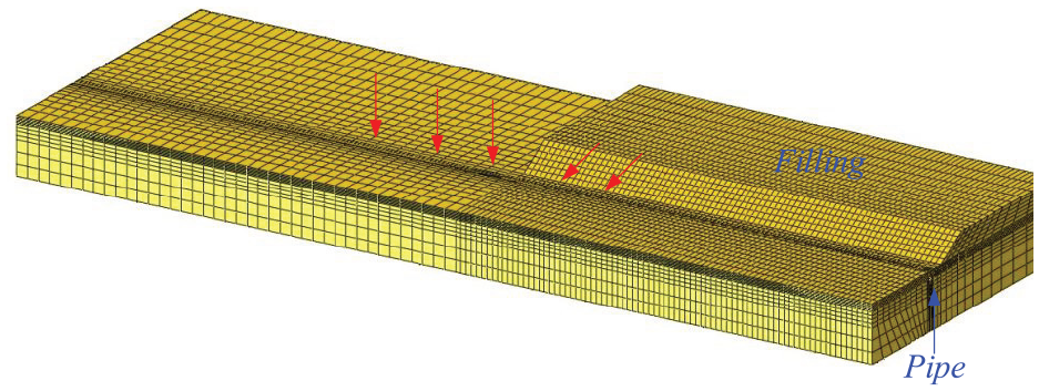
Numerical analysis model of stowage extrusion pipeline.
Due to the influence of the ground building, the pipeline moves laterally and the pipeline extends in the axial direction, resulting in the axial stress variation of the pipeline. Take a point on the surface of the pipe, and the stress variation curve along the axis of the pipeline is shown in Figure 20.

Axis stress variation curve of the pipeline (Pa).
According to the curve analysis results, the adjacent pipeline is pulled, and the other end is pressed after the pipeline moving. At a certain junction position of the pipeline, the axial stress of the pipeline is zero. The axial stress of the pipeline is equal in front of the building, and the pipelines at infinity are approximately equal.
Due to the lateral pushing of the additional load, the shear stress of the pipeline at the end of the ground building will occur. The shear stress curve along the path of the pipe is shown in Figure 21.

Shear stress of pipe along the path of pipeline axial (Pa).
For pipes are not affected by the ground building, the shear stress of the pipe section tends to be constant. In the curved part of the pipeline, the shear stress of the pipe section changes greatly.
The bending moment of the pipe section along a path is shown in Figure 22.
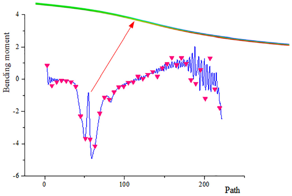
Bending moment change curve of pipe (N m).
Through the curve analysis found that the pipe section bending moment in front of the ground building, and the pipeline far away from the ground building is small, which is approximately 0. The bending moment of the pipe is large at the end of the ground building. The bending moment of the pipe approximate to 0 at a certain point of the curved part of the pipeline.
Conclusions
Through theoretical analysis, the calculation formula of the additional stress of the pipeline is obtained, and the displacement solution of the pipeline due to influence of the ground building is obtained. Combined with field construction, a numerical calculation model for the influence of the ground load on pipeline is established. Through the analysis, the following conclusions can be drawn:
(1) Ground building at a height of 25 m only affects the soil within a distance of 45 m from the edge of ground building. The soil within a depth of 20 m is greatly affected by ground building, and the equivalent stress of soft soil layers is the largest, and the maximum stress is 0.59 MPa.
(2) The closer the pipeline is to the ground building, the greater it is affected by the ground building.
(3) Due to the horizontal movement of the pipe caused by the extrusion of the additional load, a certain bending moment will appear at the boundary position of the pipeline, and the bending moment of the pipeline far from the boundary position is approximately 0. Since the pipeline is pushed laterally, the pipe section at the boundary position will produce a large shear stress. On both sides of the pipe section, one side of the pipe under pressure to produce axial compressive stress, the other side of the pipeline is pulled to generate axial tensile stress.
Footnotes
Handling Editor: Divyam Semwal
Funding
The author(s) disclosed receipt of the following financial support for the research, authorship, and/or publication of this article: This work was supported by the Chongqing Municipal Education Commission (No.KJQN202301540), and Chongqing Municipal Science and Technology Bureau (CSTB2024NSCQ-MSX0038).
Declaration of conflicting interests
The author(s) declared no potential conflicts of interest with respect to the research, authorship, and/or publication of this article.
Data availability statement
Some or all data, models, or code generated or used during the study are available from the corresponding author by request.