
Abstract
Compared with the single-side welded joint, the novel deck-rib double-sided welded joint is expected to improve the fatigue behavior of orthotropic steel decks (OSDs). Through the combination of numerical simulation and fatigue test, we have made progress in revealing the fatigue performance of double-sided welded joints of deck-ribs in orthotropic steel decks. The influence of structural parameters on the stress of key structural points is further compared. And a multi-layer perceptron (MLP) neural network was established to explore the optimal structural design parameters. Results show that fatigue behavior of crack in the inner and outer weld toes are similar. After introducing welding residual stress, the fatigue behavior of the outer weld toe deteriorated rapidly and was significantly weaker than that of the inner weld toe. In addition, the geometric parameters of the weld have a significant effect on the weld toe stress. The weld lengths of rib and deck of the outer weld are more influential than those of the inner weld, while the excess height of the inner and outer welds has a more pronounced impact on the opposite side. The proposed method provides an optimal strategy for the selection of weld parameters in the actual structure.
Keywords
Introduction
Orthotropic steel is a type of material whose mechanical properties vary significantly in different directions. This characteristic endows it with unique advantages in structural applications, especially in long-span steel bridge decks. Due to its high strength-to-weight ratio and excellent load-bearing capacity in specific directions, orthotropic steel has become a preferred material for modern bridge construction.
Orthotropic steel bridge decks (OSDs) are widely used in long-span steel beams because of their light weight, high load-bearing capacity, and prefabrication advantages. However, under the complex working conditions of long-term vehicle loads, welded joints in steel bridge decks are prone to fatigue cracking owing to the initial defects and welding residual stresses. 1 Recent studies indicate that common metallurgical defects in joints include porosity due to gas entrapment during welding, slag inclusions from incomplete slag removal, lack of fusion when base and weld metals fail to combine properly, and cracks caused by stress concentration or low material ductility.2–4 Fatigue problems are the main cause of most cracks in OSDs, especially in welded joints at deck connection locations.5,6 The structural design of a bridge has a significant impact on the failure mode of cracks in rib deck nodes. 7 In traditional single-sided welded joints, most fatigue cracks originate from welding defects at the root of the weld, and a smaller proportion originate at the toe of the weld.8,9 Subsequently, these cracks propagated through the deck and ribs, posing a serious threat to the safe operation of the bridge.
In recent years, the development of automatic robot welding technology has introduced a new type of double-sided welded joint that solves the problem of incomplete penetration and quality defects of rib-deck single-sided welded joints. 10 A double-sided welded joint formed by adding a weld on the inner side of the deck-rib can reduce the initial defects at the weld and improve the local stiffness and welding quality of the welding area.11,12 Studies have shown that under the same conditions, the fatigue life of double-sided welded joints is significantly improved compared to that of traditional single-sided welded joints. 13 The test results show that the fatigue cracking mode of a double-sided welded joint of a rib plate is different from that of a single-sided welded joint,5,14 as shown in Figure 1. Among them, type 1 and type 2 fatigue cracks initiate at the weld toe of the inner and outer welds,13,15 which are the main potential fatigue failure sites of double-sided welded joints. However, owing to the discreteness of the test results, further comprehensive fatigue tests on double-sided welded joints are required to obtain more reliable conclusions. At present, numerical analysis of the potential fatigue failure modes of double-sided welding has not clearly indicated the difference in fatigue behavior between the inner and outer weld toes. In addition, in the welding process, the inner and outer welds were single-pass and double-pass cladding welds, respectively. There was a large difference in the welding residual stress of the inner and outer welds, which had a significant impact on the two types of fatigue failure modes.
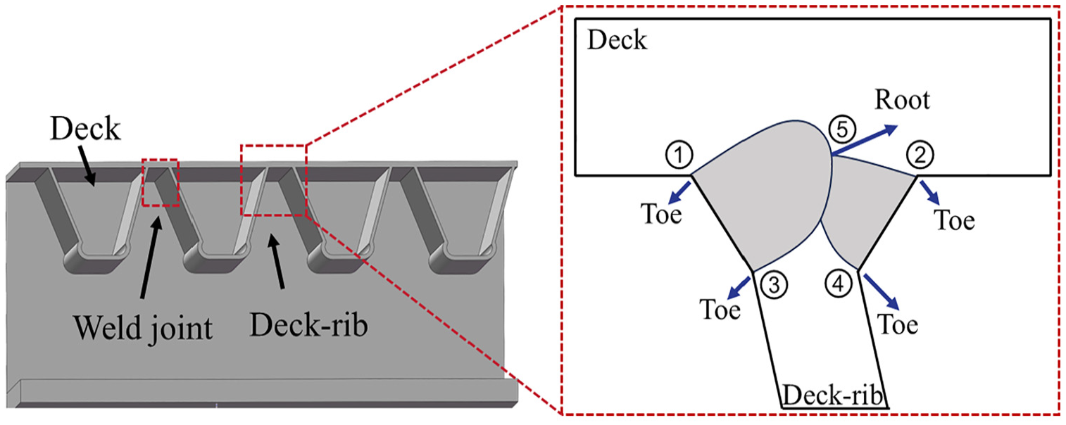
Fatigue cracks in rib-to-deck double-side welded joints.
Studies have shown that the geometric dimensions of a structure affect the fatigue behavior of welded joint.16,17 Studies on welding structures and welding parameters have shown that increasing the deck thickness can significantly improve the fatigue behavior of the weld toe, whereas increasing the deck-rib thickness has no significant effect on the fatigue life of the welded joint. 18 A fatigue life prediction method corrected by the misalignment correction coefficient was proposed to study the angle misalignment of the deck assembly. 13 Owing to the instability of the welding current and welding voltage, the weld morphology is not sufficiently smooth, which may seriously affect the characteristics of the local fatigue stress. In Figure 1, the circled parts in the red box are weld joints. Among them, ①, ③ and ②, ④ respectively represent the weld toes of the outer welded joint and the inner welded joint, and ⑤ is the weld root where the inner and outer welded joints contact. The above five are the parts that are prone to cracking in practical applications and are often used to study fatigue performance. In an experimental study of steel bridge decks, it was found that the unevenness of the weld surface caused significant stress concentration, resulting in cracking at the weld position in 9 out of 13 specimens. 19 Many studies have explored the influence of the single-sided weld morphology on the fatigue behavior and dominant failure mode of deck-welded joints. The change in weld size caused by welding manufacturing errors significantly affected the fatigue life of the bridge. The fatigue life of the weld increases with a decrease in the angle between the deck and rib, and an increase in the weld area. 20 The change in the relative weld penetration of the single-sided weld changes the dominant fatigue failure mode of the deck.21,22 The initial crack surface length and depth significantly affected the crack stress intensity factor of the double-sided welded joint of the rib plate. Therefore, initial welding defects should be strictly controlled. 11 In addition, the existing finite element analysis of weld fatigue stress is typically based on a simplified weld geometry 23 without considering the actual weld geometry details. Hence, it is necessary to further analyze the effect of weld shape on the fatigue behavior of deck-rib welds. However, owing to the existence of the inner weld in the double-sided welding of the deck, the influence of the relative weld size of the inner and outer welds on the fatigue stress of the welded joint remains unclear. In the double-sided welding process, it is necessary to optimize the double-sided weld morphology and provide reasonable weld morphology value guidance.
Compared with previous research, our study innovatively applies a multi-layer perceptron (MLP) to optimize design parameters considering the welding process while analyzing the fatigue behavior of double-sided weld joints in orthotropic steel decks. On this basis, the traditional structural parameter design method is limited in that it requires manual design and feature extraction, and it is difficult to extract key features from complex data. 24 The neural network has a strong automatic feature learning ability, among which the multi-layer perceptron (MLP) neural network is a feedforward neural network that can learn using back-propagation technology. 25 Therefore, this study attempts to introduce an MLP neural network for predicting weld geometry parameters to obtain a better combination of structural parameters.
In this study, through the combination of numerical simulation and fatigue test, the fatigue behavior of deck-rib double-sided welded joint was analyzed. Furthermore, the influence of structural parameters on the stress of key structural point is further compared. Results clarified the fatigue behaviors of the inner and outer weld toes of the double-sided weld and proposed optimal parameter requirements.
Finite element model
Rib-to-deck double-side welded joints
On the deck-welded joint in the OSDs, the residual stress remains almost unchanged in the middle part along the weld. Near the edge of the arc ignition, the tensile welding residual stress decreases sharply to zero and then becomes a compressive stress. This trend may be related to the free boundary conditions between the two. To ensure that each specimen had the same welding quality during the test, a longitudinally continuous deck and deck-rib were welded together during the manufacturing process. After overall welding, the structure was cut into local specimens with dimensions of

Schematic of the fabrication process for the same welding quality (unit: mm).
Finite element models
According to the size of the actual specimen, a finite element model of the double-sided weld joint was established in ABAQUS using solid elements, as shown in Figure 3. The simplified weld geometry morphology includes deck weld length
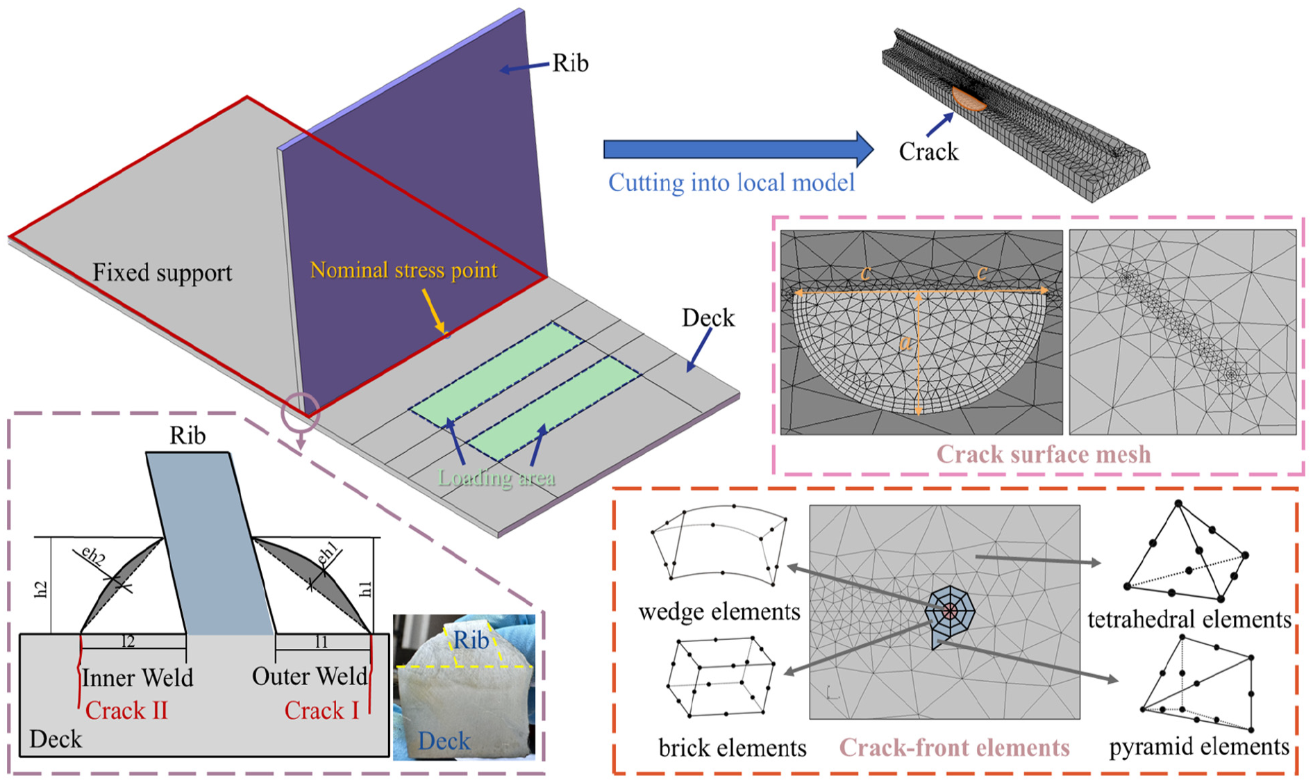
Finite element model of double-sided weld joints (unit: mm).
The selection of the meshing strategy can lead to variances in the analysis outcomes. To enhance the calculation accuracy and alleviate the computational burden, the mesh size of the model was set to 2 mm, with a refined mesh size of 1 mm applied within a 20 mm range around the weld.28–30 FRANC 3D employs a default configuration of eight wedge elements surrounding the front, and two concentric rings of brick elements. The initial mesh of the crack front was categorized into four types, progressing from the innermost to the outermost. To ensure compatibility between the bricks and tetrahedra, quarter-point singular wedge crack-front elements are assigned to the innermost crack layer, brick elements occupy the middle layer, and pyramid elements form the outermost layer. To preserve compatibility, the middle layer was composed of brick elements, whereas the outermost layer was constructed using pyramid elements. The volume mesh of the global model predominantly employed tetrahedral elements.
Experimental validation
Specimens
Fatigue tests were performed on four-deck double-sided welded specimens to verify the validity of the finite element model. All the specimens were made of Q345qD steel, which is a common structural material for steel bridges in China. After testing, the chemical composition test results and mechanical property test results of the local full-scale specimens of this batch comply with “Structural Steel for Bridges” (GB/T714-2008) as shown in Tables 1 and 2. The deck and deck-rib were welded using 100% full-penetration double-sided submerged arc welding. The angle between the deck-rib and the deck was 78°. More detailed geometric dimensions are shown in Figure 4.
Chemical composition of steel (%).

Mechanical properties of steel.


Details of test specimens (unit: mm).
The deck and deck-rib are joined by 100% double-sided full-penetration submerged arc welding. For the internal welding, it is conducted in the transverse position with a welding current of 380 ± 30 A and a welding voltage of 34 ± 2 V. The external welding, using the submerged arc welding method, is carried out in the ship position, with a welding current of 630 ± 40 A and a welding voltage of 36 ± 2 V. The weld foot size is set at 8 mm. Once the welding is completed, the surface of the weld is refinished with a grinding wheel.
Load and test details
Under a vehicle load, the rib-to-deck welded joints primarily endure a localized bending stress. Testing full-size specimens in a laboratory is challenging.22,31 Research has demonstrated the utilization of mechanical fatigue-testing machines to apply cyclic loads on localized specimens of welded structures. This approach enables the acquisition of detailed fatigue behavior data and allows adjustments to the stress ratio using a spring mechanism. A depiction of the test loading particles is shown in Figure 3. To ensure that the inner and outer weld toes had the same boundary conditions and load conditions during loading, the specimen was affixed to the loading platform using bolts, while the cantilever end on the opposite side was connected to the mechanical fatigue testing machine. The stress is generated by the rotation of the eccentric wheel in the actuator of the mechanical fatigue testing machine. To ensure that the inner and outer weld toes had the same boundary conditions and load conditions during loading, the specimen was installed in reverse to obtain the stress characteristics of the inner weld toe (Figure 5).

Schematic diagram of test setup.
Five strain gauges, labeled 1–5, were installed in each specimen at the designated locations, as illustrated in Figure 4. Following the guidelines of the International Institute of Welding (IIW), 32 the nominal stress, which excludes stress concentration, represents the fatigue resistance of the SN curve for different structural elements; therefore, the measuring points must be positioned outside the stress concentration regions. The nominal-stress measurement point was located 10 mm from the weld toe. Here, the stress gradient flattened and strain gauge 5 regulated the testing stress amplitude. The fatigue test applied stress amplitudes of 120 and 100 MPa to double-sided welded components. A schematic of the fatigue test specimens is presented in Table 3.
Scheme of the fatigue test specimens.

Validation of FEM
Figure 6 presents the nominal stresses at the weld toes of both the test specimen and finite element model. In the experiment, the test result of SG5 was taken as the nominal stress loading amplitude of the experiment. The difference between the finite element calculation results and test stress value was characterized by
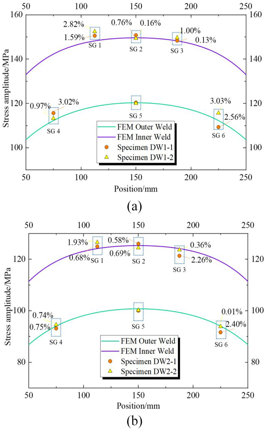
Stress of test specimen and FEM: (a) stress amplitude 120 MPa and (b) stress amplitude 100 MPa.
Fatigue behaviors of double-side weld
Fatigue strength
Among the four specimens, three experienced fatigue failure with inner weld toe cracking, and one with outer weld toe cracking. The fatigue life of the specimens was evaluated using the S-N curve method. Based on the test failure life and nominal stress amplitude, the S-N curve of the fatigue specimen with a deck thickness of 12 mm was constructed. These curves are shown in Figure 7. In addition, the figure shows the prescribed curves for the strength of double-sided weld structures according to various national standards. The prescribed strength of the corresponding details in the Chinese Highway Steel Bridge Design Code is 80 MPa. 26 The strength prescribed by Japanese Society of Steel Construction (JSSC for short) is 100 MPa. 33 The strength of the structural details prescribed by the British standard BS5400 is 40 MPa. 34 After fitting the fatigue test results of the four specimens, the stress amplitude corresponding to 2 million cycles was used as the fatigue strength. The fatigue strength of the deck double-sided full-penetration weld was 145 MPa, which was significantly higher than the strength of the corresponding structures in the three standards.

Fatigue strength of test specimens in double-sided welds.
Stress concentration factor
The stress concentration factor can be calculated by computing the ratio of the hot spot stress

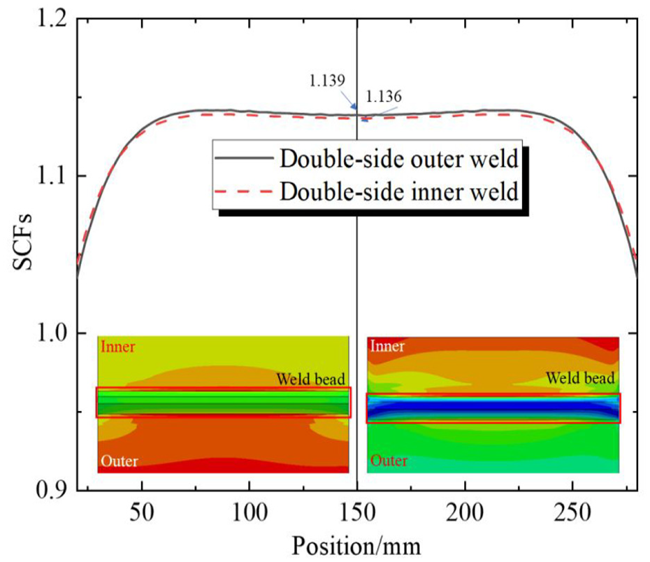
SCFs of rib-to-deck double-side weld joints.
Toes near the inner and outer center axes in the stress cloud diagram. The stress concentration coefficient suddenly decreased within 50 mm near the free edges on both sides owing to the lack of constraints. An area with a high stress concentration coefficient may decrease the strength of the weld, which is usually the main location for fatigue crack initiation and damage. Consequently, it affects the overall strength of the structure. By further analyzing the stress concentration phenomenon of the weld, the influence of the welding process and weld morphology on the stress can be identified. Therefore, the middle part of the weld should be studied as much as possible during testing and subsequent finite element analysis. In addition, when the load position is symmetrical on both sides of the deck-rib, the stress concentration coefficients of the inner and outer weld toes are similar. The difference between the stress concentration coefficients of the center axis of the double-sided weld toe and the inner weld toe was very small. This indicates that the 78° flange angle between the deck-rib and deck had little effect on the stress concentration of the inner and outer weld toes.
Crack propagation
Fatigue crack propagation refers to the process in which cracks gradually grow and eventually break under cyclic loading. Studying this process can help predict and evaluate the service life of materials, further clarify the fatigue behavior of materials, and optimize the design and manufacture of welded joints. Regarding the crack initiation mechanism, stress concentration at the weld toe is of vital importance. It is mainly triggered by geometric discontinuities and potential initial defects. For example, small notches or inhomogeneities in the weld morphology can cause such stress concentration. Under cyclic loading, these stress-concentrated areas become the preferred spots for crack initiation. When the load acts repeatedly, the stress at these locations surpasses the strength limit of the material, ultimately resulting in the generation of micro-cracks. 35
Figure 9 shows the crack propagation process of the inner and outer weld toes of the double-sided weld of the deck with the same initial defect. Under the same load stress amplitude, the fatigue lives of the inner and outer weld toes did not differ by more than 7%. However, in actual bridges, when there is a certain deviation between the load and the relative position of the deck-rib, the fatigue stress amplitude of the inner and outer weld toes changes significantly. The fatigue life of the deck weld joint is significantly affected by the stress amplitude; therefore, the inner and outer weld toes are potential fatigue crack initiation locations. The growth rate of the fatigue cracks in the surface length direction was significantly higher than that in the depth direction. Tensile stress is the main driving force for crack propagation and promotes crack opening, plastic deformation, and crystal tearing at the crack front, resulting in rapid crack propagation. The growth rate of fatigue cracks in the width direction was significantly higher than that in the depth direction, and the growth of fatigue cracks in the inner weld toe was more significant than that in the outer weld toe. The initial shape of the crack was semicircular, which gradually evolved into a semi-elliptical shape under the action of cyclic loading, and the ratio of its major axis to the minor axis gradually increased. However, the growth of fatigue cracks is not only affected by the load boundary conditions but also by the welding quality and welding residual stress.

Crack propagation of inner and outer weld toes in double-sided welds.
Effect of welding residual stress
Cladding submerged arc welding was used at the outer weld of double-sided welding, and single-layer submerged arc welding was used at the inner weld. Owing to the influence of the two welds, the residual stress of the outer layer was greater than that of the inner layer. According to the residual stress test results of double-sided welding, there was a large residual tensile stress at the weld in the welded joint. On the deck, the surface residual stress of the outer weld was 160 MPa and the lower surface was 90 MPa, while the residual stress of the upper and lower surfaces of the deck of the inner weld was 90 MPa, and it was linearly distributed in the thickness direction of the deck. To evaluate the effect of residual stress on fatigue life, we applied residual stress in Franc3d and used Walker’s formula based on the Paris extended model to correct the stress ratio change caused by the residual stress, as shown in equation (2).


Considering the influence of the residual stress of the inner and outer welds on the crack propagation, the corresponding situation is shown in Figure 10. Compared with the inner weld toe, the crack in the outer weld toe had a significantly faster propagation rate in the depth and surface width directions. When the same crack size was reached, the fatigue life of the inner weld toe was at least 68% longer than that of the outer weld toe. The two welds had a weakening effect on the fatigue life of the outer weld toe, which was lower than that of the inner weld toe. Therefore, when performing full-penetration double-sided welding, it is recommended to select the welding process parameters reasonably and take measures. This includes heat treatment during processing to reduce the residual stress.

Crack propagation considering WRS: (a) welding process and WRS and (b) crack propagation curve considering WRS.
Parameters analysis
Weld length of deck
Changes in the welding process led to differences in the final morphology of the welds. For double-sided welding, there were two welds on the inner and outer sides. The influence of the morphology of these welds on the double-sided welding and fatigue crack generation process remains unclear. Further research is needed to study whether the fatigue failure mode of the inner and outer weld toes of double-sided welding differs with changes in the weld parameters. According to relevant literatures and research, the length of weld leg of the inner and outer welds on the deck and deck-rib affects the fatigue behavior of the welded joint. The effect of the distance between the inner and outer welds on the fatigue behavior can be ignored. Therefore, the objective of this study was to achieve full-penetration double-sided welding, and the distance between the inner and outer welds was set to 0 mm. To explore the influence of the length of deck weld legs on the fatigue failure mode and the corresponding weld toe stress, based on the finite element model in Section “Finite element model,” a total of 14 groups of models were established respectively. For these models, the lengths of the deck welds at the inner and outer weld toes are set as 6, 7, 8, 9, 10, 11, and 12 mm, which represent different weld leg lengths, while other parameters remain unchanged.
Results showed that increasing the length of deck weld leg at the inner and outer weld toes increased the stress at the inner and outer weld toes, thereby reducing the fatigue behavior at the weld toes. In addition, considering that an increase in deck weld leg length will increase the local stiffness of the deck weld, it will aggravate the stress concentration phenomenon and lead to greater stress. Simultaneously, a larger weld leg size will cause more potential welding defects, thereby affecting the fatigue life of the component. Therefore, it is recommended that the length of the deck weld legs take the minimum value (Figure 11).

Stress of weld toe in different wide length of deck.
Weld length of rib
In orthotropic steel bridge decks, in addition to the length of deck weld leg, the length of deck-rib weld leg is a potential factor affecting the fatigue behavior of the deck-rib full-penetration double-sided weld structure. According to the finite element model, 14 models were designed, in which the lengths of deck-rib weld leg were 6, 7, 8, 9, 10, 11, and 12 mm, and the other welding parameters remained unchanged. The calculation results are shown in Figure 12.

Stress of weld toe in different wide length of rib.
It can be observed from the figure that increasing the length of the outer deck-rib weld leg reduced the stress of the outer weld toe and slightly increased the stress of the inner weld toe. When the lengths of deck-rib weld leg were the same, the stress of the outer weld toe reached the maximum value, whereas the stress of the inner weld toe was the minimum. Conversely, increasing the length of the inner deck-rib weld leg reduced the stress on the inner weld toe. When the length of the inner and outer weld legs of deck-rib were the same, the stress of the inner weld toe reached the minimum value, whereas the stress of the outer weld toe remained essentially unchanged as the length of the inner deck-rib weld leg increased. Therefore, it is recommended that the lengths of the inner and outer deck-rib weld legs should be consistent and take the maximum value.
Weld excess height
Weld excess height refers to the height difference between the weld and the surface of the substrate. Weld excess height formed during welding has an important influence on the behavior and reliability of welded structures. In deck fillet weld structures, weld excess height is inevitable in the weld joint. In the finite element model described in Section “Finite element model,” weld excess height of 1, 2, and 3 mm were designed for the inner and outer weld toes, and the stress values of the inner and outer weld toes were extracted, as shown in Figure 13.
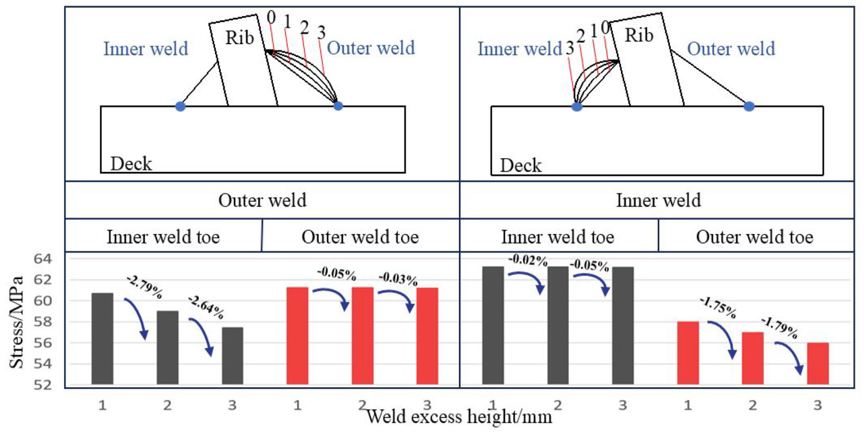
Stress of weld toe in different weld excess height.
It can be observed from the figure that increasing the inner and outer weld excess height can reduce the stress of the weld toe on the opposite side and has little effect on the stress of the weld toe on the corresponding side. Excess height of the deck weld can form a local bulge at the weld, thereby alleviating the stress concentration at the weld toe to a certain extent. This bulge disperses the stress at the weld position and distributes it more evenly in the area near the weld, thereby reducing the degree of stress concentration at the weld. However, excessive weld excess height increases the potential welding defects and stress concentration at the weld. Therefore, according to the specification requirements, the weld excess height should be less than 10% of the parent material thickness, and the single maximum weld excess height should not exceed 25% of the parent material thickness. Therefore, it is recommended that the weld excess height be properly controlled to meet the requirements of the specifications.
Structural parameter optimization design
In the structural parameter design, the application of neural networks has significant advantages over traditional methods. The traditional methods rely on manual design and feature extraction. When faced with complex data, it is difficult to accurately extract key features. However, neural networks possess powerful automatic feature-learning capabilities. The multi-layer perceptron neural network (MLP), as shown in Figure 14, is a feed-forward neural network that learns through the backpropagation technique.
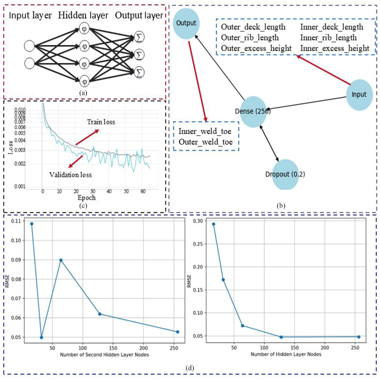
Model construction and optimization: (a) architecture of MLP, (b) model structure, (c) relationship between Loss and Epoch, and (d) RMSE vary with the number of hidden layer nodes.
The architecture of a Multi-Layer Perceptron neural network consists of a neuron input layer as a receiver, one or more hidden layers responsible for calculating data and iterating, and an output layer for predicting the input.
The model structure used in this study applied the MLP neural network. Its purpose was to predict the minimum stress values and related parameters of the inner and outer weld toes in the welded structure. The input features include the deck weld length of the inner toe, deck weld length of the outer toe, inner weld toe deck-rib weld leg, outer weld toe deck-rib weld leg, outer weld excess height, and inner weld excess height. The output was the minimum stress value of the inner and outer weld toes. The network structure was composed of an input layer, two hidden layers, and an output layer. The dimensions of the input layer are 6. After repeated verification, when both hidden layers were set to 256 neurons, the loss function reached its minimum value. Each layer uses the ReLU activation function and adds L2 regularization; the output layer has two neurons. This structure demonstrated excellent behavior for both the training and validation sets.
During the training process, there is a close relationship between the Loss and Epoch. As the training progressed continuously, the epoch gradually increased, and the loss first showed a trend of rapid decline and then gradually stabilized. This indicates that the model can learn rapidly during the initial training stage. As the training progressed, the learning speed gradually slowed until a relatively stable state was reached.
In addition, the RMSE changed with the number of hidden layer nodes. In this study, through tests on different numbers of hidden layer nodes, it was found that when both hidden layers had 256 neurons, the RMSE reached a relatively low level, further verifying the rationality and effectiveness of the model structure. For the same structure, the greater the inner and outer stresses are, the easier it is to fail. Therefore, the larger value of the output stress of the inner and outer weld toes is taken as the judgment value, and the minimum judgment value is the optimized parameter of the structure sought.
According to the model prediction results, within the experimental range, when the length of inner deck weld leg is 7 mm, the length of outer deck weld leg is 6 mm, the length of inner deck-rib weld leg is 9.85 mm, the length of inner deck-rib weld leg is 9.85 mm, the length of outer deck-rib weld leg is 11 mm, the outer weld excess height is 3 mm, and the inner weld excess height is 3 mm. The corresponding inner weld stress is 57.36 MPa and outer weld stress were 55.93 MPa. In other words, the structure has the highest intensity under these parameters.
Conclusions
(1) The dominant fatigue failure modes are cracks initiating at toes of the deck-rib double-sided weld and penetrated the deck. After the crack initiating at the weld toe, the fatigue cracks propagated significantly faster on the surface than in the depth direction. And the propagation rate of the inner weld toe was slightly greater than that of the outer weld toe.
(2) Fatigue behavior of crack in the inner and outer weld toes are similar. After considering welding residual stress, the fatigue life of both reduced, while the outer weld toe deteriorating more seriously. Therefore, heat treatment after welding is recommended to reduce the welding residual stress and improve the fatigue life.
(3) Increasing the length of the weld legs of deck increased the stress of the weld toes. Increasing the length of outer weld leg of deck-rib reduced the stress on the outer weld toes and slightly increased the stress on the inner weld toes. When the lengths of the inner and outer weld legs of deck-ribs were the same, the stress of the inner weld toes was the lowest. Therefore, it is recommended that the length of deck weld legs take the minimum value. The lengths of the inner and outer deck-rib weld legs should be consistent and take the maximum value.
(4) An appropriate increase in weld excess height can reduce the weld toe stress on the opposite side and has little effect on the weld toe stress on the corresponding side. However, excessive weld excess height increases the potential welding defects and stress concentration at the weld. Moreover, neural network performs well exploring the optimal structural design parameters. Therefore, it is recommended that the weld excess height should be controlled according to the requirements of the specifications. And the optimal parameters can be explored through neural networks.
Footnotes
Handling Editor: Liyuan Sheng
Funding
The author(s) received no financial support for the research, authorship, and/or publication of this article.
Declaration of conflicting interests
The author(s) declared no potential conflicts of interest with respect to the research, authorship, and/or publication of this article.
Data availability statement
All data that support the findings of this study are included within the article (any supplementary data will be available upon reasonable request).