
Abstract
Active magnetic bearings (AMBs) are widely used in high-speed turbines, precision machining, and energy storage systems due to their non-contact operation, high rotational speeds, and low maintenance. The 8-pole radial magnetic bearing (RMB), commonly adopted in AMB systems, faces limitations in load-carrying capacity and space utilization under heavy loads. To address this, a 12-pole RMB with E-type magnetic poles is proposed, enhancing stator space utilization and electromagnetic force generation. However, optimizing the 12-pole RMB is challenging due to the trade-off between maximizing electromagnetic force and minimizing stator volume, with limited research on its multi-objective optimization. This study fills this gap by systematically investigating the structural design and optimization of the 12-pole RMB. A mathematical model using an equivalent magnetic circuit is developed, validated by Finite Element Method (FEM) simulations, showing strong agreement. FEM further assesses magnetic flux density, dynamic performance, and structural parameter effects. Using the NSGA-II algorithm, a multi-objective optimization framework optimizes the conflicting objectives, selecting six key variables based on their Pareto effect. A prototype of the optimized 12-pole RMB is fabricated and tested, demonstrating stable levitation and confirming the design’s effectiveness. This study offers a systematic approach for designing 12-pole RMBs, providing valuable insights for industrial applications.
Keywords
Introduction
Active magnetic bearings (AMBs), originally designed to address the limitations of conventional journal or ball bearings, demonstrate several advantages, including the ability to operate in vacuum environments without lubrication or contamination, as well as the capability to achieve higher rotational speeds. 1 These systems utilize passive or controllable electromagnetic forces to achieve non-contact rotor levitation, offering key benefits such as frictionless operation, reduced maintenance requirements, low vibration levels, higher rotational speeds, and enhanced operational reliability. A notable feature of AMBs is their ability to adjust damping and stiffness during operation, which allows for customization to meet various operational needs.2,3 As a result, AMBs have found widespread applications in fields such as industrial turbine machinery, compressors, aerospace systems, energy storage devices, milling spindles, and medical equipment.4–7
In an active magnetic bearing (AMB) system, stable rotor levitation is achieved through the coordinated operation of displacement sensors, microcontrollers, control algorithms, power amplifiers, and actuators.8,9 Among these components, actuators play a critical role, as they receive control currents from the power amplifier and generate electromagnetic forces that maintain rotor levitation at each computational step.10–12 Typically, actuators are classified into radial magnetic bearings (RMBs), which provide stabilization in two degrees of freedom (DOF), and axial magnetic bearings, which stabilize the rotor in one DOF. A standard AMB configuration consists of two RMBs and one axial bearing. 13 Among these, RMBs have attracted significant research interest due to their essential role in supporting multi-DOF stabilization within magnetic bearing systems.14,15
Depending on their structural configurations, radial magnetic bearings (RMBs) can be classified as either homopolar or heteropolar types. A homopolar RMB has poles of the same polarity within the same rotation plane, while a heteropolar RMB alternates its polarity perpendicularly. In practice, heteropolar RMBs are more commonly used in industry due to their simplicity and lower cost. 16 Various heteropolar configurations are employed in applications requiring three, four, eight, twelve, or sixteen poles. Among these, the 8-pole RMB has attracted considerable research interest and is widely adopted in industrial applications. Numerous studies have focused on the design,17–19 power loss,20,21 and optimization22,23 of 8-pole RMBs.
However, the limitations of the 8-pole RMB become evident as the demand for higher load capacity increases, particularly with larger rotor diameters. In an 8-pole RMB, the large gaps between stator poles result in inefficient space utilization, thereby restricting the generated electromagnetic force.24,25 Additionally, the magnetic flux in the poles of an 8-pole RMB tends to saturate rapidly under heavy loads. 26 To overcome these challenges, an E-type magnetic pole configuration was developed by dividing each C-type magnetic pole into two sub-poles, increasing the pole count from eight to twelve. This modification optimizes space utilization between pole pairs, accommodating additional magnetic poles and windings. For the same stator diameter, the 12-pole RMB demonstrates superior load capacity and enhanced controllability compared to the 8-pole configuration. 27 Moreover, the reduced magnetic field coupling between poles makes the 12-pole RMB more suitable for applications requiring high load capacity in constrained spaces.28,29 Comparative studies have quantified the improvements of the 12-pole RMB over the 8-pole configuration. Dimond et al. reported a 10% increase in load capacity when transitioning from 8 to 12 poles, 30 while Zhan and Zhu analyzed the relationships between the outer-to-inner stator diameter and losses with respect to frequency for both 8-pole C-type and 12-pole E-type RMBs, as shown in Figure 1. Additionally, the 12-pole RMB exhibits a reduced axial length compared to the 8-pole RMB, enhancing its compactness. 31 Owing to these advantages, the E-type 12-pole configuration has been widely adopted by commercial Active Magnetic Bearing (AMB) manufacturers. 32

The comparison of C type and E-type magnetic pole with regard to stator diameter (a) and losses (b) by Zhan and Zhu. 31
Compared to the extensive research on the design, modeling, analysis, and optimization of 8-pole radial magnetic bearings (RMBs), the 12-pole RMB has received relatively limited attention. Wang et al. 33 modeled and analyzed a hybrid permanent-magnet-biased E-type RMB, demonstrating advantages such as high stiffness and low channel coupling. Saeed et al. 34 investigated the nonlinear dynamics and bifurcation behavior of a 12-pole RMB, and experimentally evaluated its vibration response under a designed controller. Hamad et al. 35 optimized the AMB design by reducing the number of poles and air gap size. Kumar et al. 25 explored the use of AC excitation in 12-pole RMBs to counteract rotor unbalance. Ren and Ma 36 focused on the dynamic stability and vibration characteristics of 12-pole RMBs under PD control.
Despite the increasing importance of 12-pole radial magnetic bearings in industries, there remains a significant gap in the literature concerning their systematic design and optimization. And the design of magnetic bearings requires significant time, cost, and advanced knowledge in mechanical and electrical engineering, making the optimization of compact, efficient, reliable magnetic bearing systems a key research focus in the field. Existing studies often lack a unified framework that addresses both the preliminary design phase and the optimization process. To bridge this gap, this paper proposes a comprehensive and structured methodology for the design and multi-objective optimization of 12-pole RMBs, incorporating critical engineering constraints. This approach not only enhances the design efficiency but also ensures practical applicability for heavy load magnetic bearing systems. The proposed method represents a novel contribution by offering detailed guidance for 12-pole RMB development, serving as a valuable reference for both industrial applications and academic research.
This paper presents a comprehensive framework for the modeling, design, and multi-objective optimization of the 12-pole RMB. The remainder of the paper is structured as follows: Section “Modeling of 12-pole RMB” introduces the fundamental operating principles and establishes the nominal mathematical model for the bearing. Section “Preliminary design and analysis of 12-pole RMB” describes the preliminary structural design process and includes performance simulations of the initial design. Section “Optimization design of 12-pole RMB” outlines the cost functions, design variables, and constraints that are integral to the optimization process, along with an analysis of the performance of the optimized structure. Section “Experiment test” presents the levitation performance data collected during the experiment, and Section “Conclusion and future work” concludes with key insights and directions for future research.
Modeling of 12-pole RMB
Working principle of 12-pole RMB
The basic operating principle of a 12-pole radial magnetic bearing is illustrated in Figure 2. The single-degree-of-freedom (SDOF) system comprises several key components, such as the rotor, an E-type stator, displacement sensors, power amplifier, and windings arranged in differential control method. This configuration enables the electromagnets to achieve faster response times. Stable levitation of the rotor is maintained through a classic feedback control process: the position of the rotor is detected by non-contact sensors, and the sensor’s output voltage is sent to the controller, which calculates the necessary control signal. This control signal is then converted into a control current for the differential coils through power amplifiers. Finally, the resulting differential electromagnetic force attracts the rotor, bringing it back to its equilibrium position. This feedback control process occurs in microseconds and is repeated continuously, allowing for the levitation of the rotor.

(a) Illustration of structure and (b) working principle of SDOF 12-pole RMB.
Figure 3(a) illustrates the basic structure of a 12-pole radial magnetic bearing, which consists of 4 central magnetic poles with larger pole areas and 8 sub-magnetic poles with smaller areas. 33 The distribution of the E-type magnetic poles is typically arranged in an “NSN” or “SNS” layout to minimize the potential cross-coupling of magnetic circuits between different pole groups. In general, the magnetic pole area and the number of coils turns in the central poles are twice those of the sub-magnetic poles, which simplifies the design and analysis. Two sets of single-degree-of-freedom (SDOF) differential control coils, aligned along the x-axis and y-axis, generate cooperative forces to levitate the rotor and counteract external disturbances.

(a) Basic structure of 12-pole RMB and (b) its simplified equivalent magnetic circuit.
In the design and analysis of magnetic bearings, the equivalent magnetic circuit method is widely used due to its straightforward representation, which is achieved through appropriate simplifications. The magnetic circuit of 12-pole RMB is shown in Figure 3(b). A set of E-type magnetic pole group (e.g. magnetic pole 1, 2, and 3) consists of electromotive force (Ni), the magnetoresistance of air gap, stator and rotor (R), as well as magnetic flux (
Mathematical modeling of 12-pole RMB
Considering a E-type magnetic pole group shown in Figure 4(a), the two magnetic circuits within a E-type magnetic pole group can be expressed by Ampere loop theorem by proper simplification as:

Where, Ncentral represents the number of coils of the central magnetic pole; I represent the excitation current in the E-type magnetic pole. The symbols Hfe and Hair represents the magnetic field strength of the core and air gap, respectively. lfe is the circuit length in the core, and δ0 is the displacement of the air gap.

(a) Structure and ideal magnetic paths of a group of E-type magnetic pole and (b) its detailed structure descriptions.
By introducing

Where,
According to MAXWELL electromagnetic force formula

Where,
Given the relationship of

Where,
Therefore, the electromagnetic force generated by a E-type magnetic pole can be deduced as:

Considering the differential control of two sets of E-type magnetic pole shown in Figure 2(b), the resultant force excited to rotor is the sum of
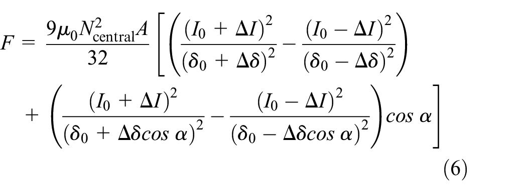
By taking Tylor’s expansion at the set equilibrium point (

Where,
Preliminary design and analysis of 12-pole RMB
Preliminary design flow of 12-pole RMB
The primary objective in designing radial magnetic bearings is to achieve maximum load capacity alongside optimal dynamic performance. The detailed methodology for the preliminary design of a 12-pole radial magnetic bearing is systematically outlined in Figure 5.
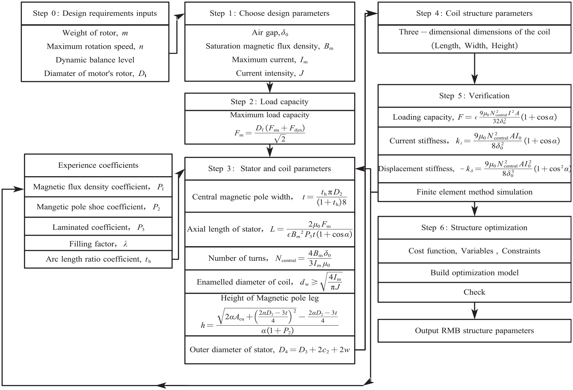
Preliminary design procedure of 12-pole RMB.
Step 0: Design inputs
The mass of rotor
Preliminary parameter list of 12-pole rmb.

Step 1: Initial parameters
Several parameters have to be selected at the beginning of the design process. The air gap
Step 2: Loading capacity calculation
Determining the maximum load capacity is the primary objective in the design of RMB. The target loading force of a group of E-type magnetic poles can be calculated by multiplying the static load

Where,
The static load capacity

Where,
By taking values into (9), the demanded maximum load capacity
Step 3: Determining stator and winding parameters
As is shown in Figure 4(a), the inner diameter of the stator can be expressed as
The maximum allowable magnetic flux density

The width of central magnetic pole

In common configurations of 12-pole RMB, the width of sub-magnetic pole is half of that value of
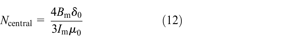
The number of turns of central magnetic pole can be derived by placing the value of
The pole face area of central magnetic pole
Also, the diameter of winding coil

What is worth mentioning is that in practical design, the value of
The sector area
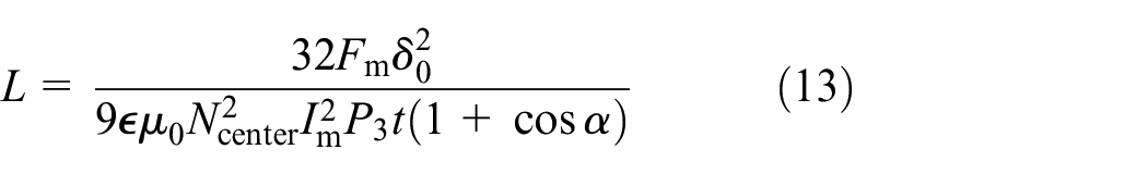
At the same time, the value of

Where,

Then, the outer diameter of the RMB stator

Where,
Step 4: Determining winding dimensions
Unlike the 8-pole RMB, where the magnetic pole and winding sizes are equal, the coils of the central and sub-magnetic poles in 12-pole RMB may cause mechanical interference. To mitigate this, the maximum available coil width for the central magnetic pole

Where, the factor

(a) Illustrations for maximum winding width and (b) cross-sectional area parameters.
Once the maximum winding width is determined, the number of layers and rows can be calculated according the value of
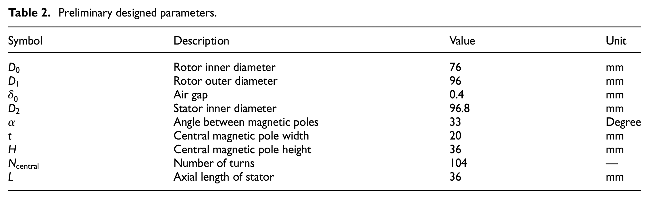
The preliminary designed parameters for the 12-pole RMB, based on the requirements for mass, rotational speed, dynamic balance level, and motor diameter, are summarized in Table 2.
Preliminary designed parameters.
Characteristics of the 12-pole RMB
A finite element method model (FEM) is developed and analyzed by MAXWELL software based on the parameters listed in Table 2.
Figure 7(a) and (b) illustrates the maximum magnetic flux density distribution and vectors when maximum current

(a) Magnetic flux density distribution and (b) vectors distribution.
Figure 8 illustrates the interdependencies among electromagnetic force, control current, and displacement within a differential control group. In the central operating range of both control current and displacement, the current stiffness and displacement stiffness exhibit strong linearity; however, this linearity degrades as the silicon steel material approaches saturation under maximum current conditions.
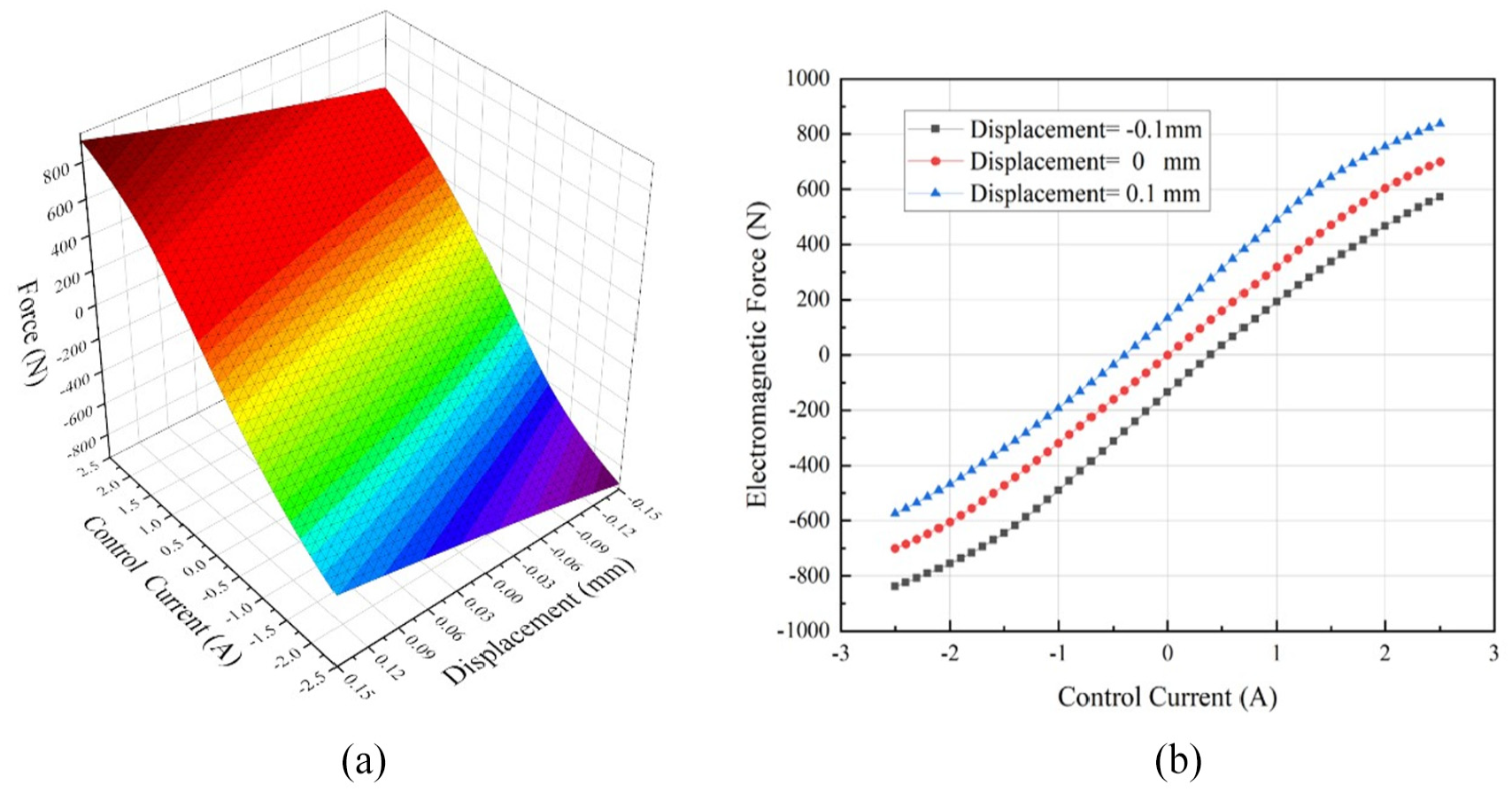
(a) The relationship between electromagnetic force, control current, and displacement and (b) the relationship between electromagnetic force and control current under different displacements.
To assess the impact of design parameters on levitation forces, a set of E-type magnetic pole groups is analyzed by simulation. As shown in Figure 9(a), the electromagnetic force increases with the thickness of the rotor
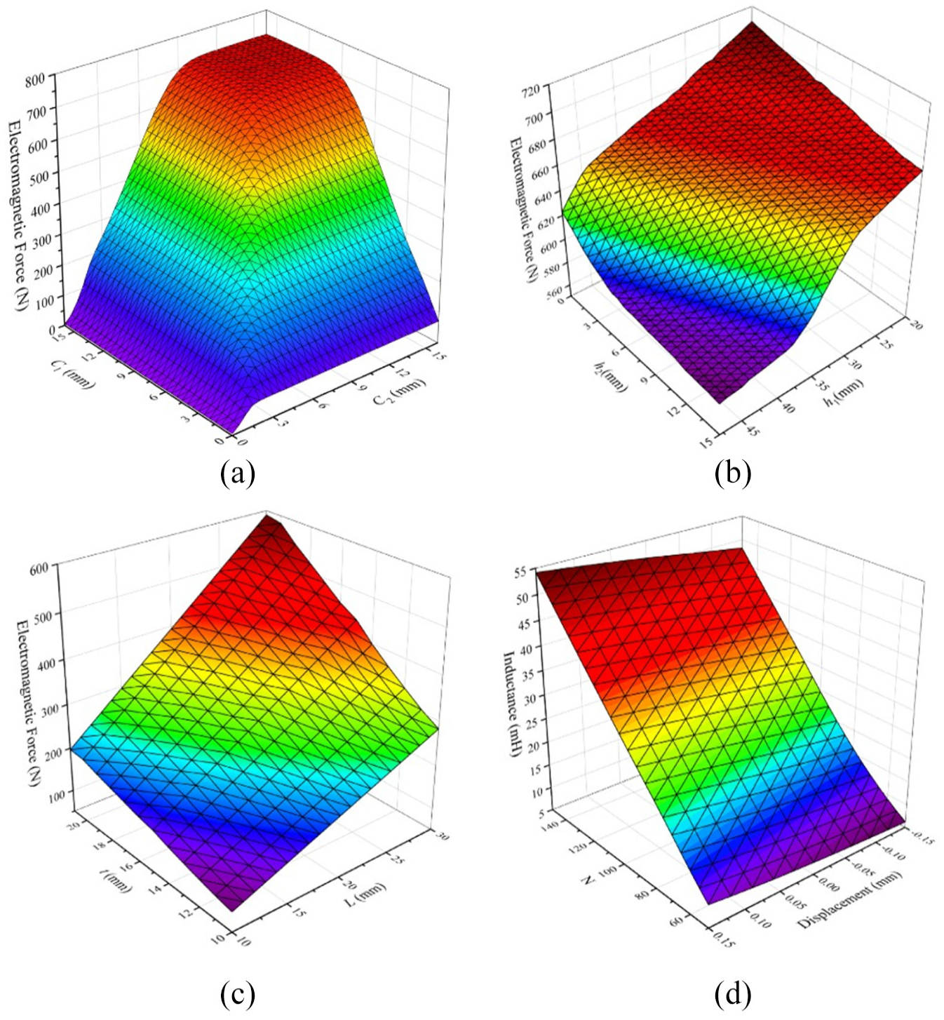
(a) The influence of c1 and c2 to electromagnetic force, (b) the influence of h1 and h2 to electromagnetic force, (c) the influence of t and L to electromagnetic force, and (d) the influence of N and
Optimization design of 12-pole RMB
Based on the preliminary design results presented in Table 2, a multi-objective optimization is conducted using the Non-dominated Sorting Genetic Algorithm II (NSGA-II) 37 in ISIGHT, which has been widely applied to various engineering design problems and is often regarded as a benchmark against which other optimization algorithms. 38 The cost functions, design parameters, and constraints are described in the following section. The results of the optimization are subsequently presented and analyzed.
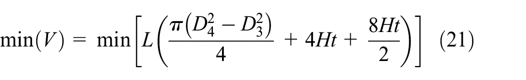
Objectives
In this optimization design, two conflicting objectives were selected to guide the performance improvement of the 12-pole Radial Magnetic Bearing (RMB): maximizing the magnetic force (equation (20)) while minimizing the stator volume (equation (21)). These objectives are critical for enhancing the bearing’s load-carrying capacity and ensuring compactness, which are essential for practical applications in high-speed rotating machinery. These two objectives are inherently conflicting, as increasing the magnetic force typically requires larger magnetic poles or higher currents, which in turn increases the stator volume, while minimizing the stator volume may compromise the magnetic circuit ability to generate sufficient force. This trade-off necessitates a multi-objective optimization approach, which was addressed using the NSGA-II algorithm to identify the Pareto front solutions, as discussed in the following sections.

Selection of variables
The variables involved in the optimization process must be carefully selected, as they directly influence the efficiency, convergence behavior, and overall quality of the optimization outcomes. For the 12-pole RMB structure, seven variables were identified for analysis: magnetic pole angle (α), pole height (H), maximum control current (I), axial length (L), coil number of the central pole (N), magnetic pole width (t), and thickness of the stator yoke (c2). To evaluate their impact on the optimization objectives, the optimal Latin Hypercube method39,40 was applied with 200 sampling points, and the resulting Pareto effect plot is presented in Figure 10.

Pareto response plot to magnetic force (in blue) and volume (in green).
The analysis reveals that the variable α has significantly less influence on both objectives compared to the other six variables. Consequently, the remaining six variables were selected for further optimization analysis.
Constraints
Constraints on magnetomotive force
The maximum magnetomotive force of central magnetic pole generated by
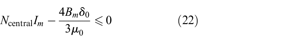
Also, the magnetic flux density in the stator yoke and poles should be restricted below the saturation flux density
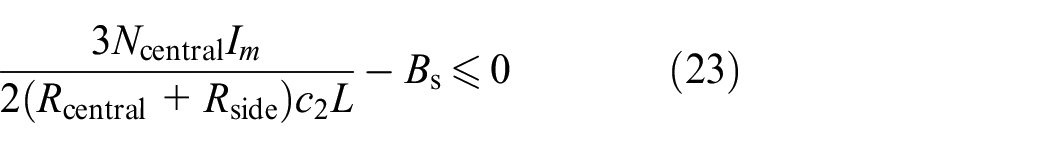

Where,
Constraints on available winding space
The maximum winding space available between central and sub-magnetic pole should be constrained by assuming a winding space filling factor

Similarly, the winding space between two sub-magnetic poles should be constrained as:

Where,
Constraints on avoiding coil interface
The windings of the central and sub-magnetic poles may interfere with each other if the design is not properly optimized. To mitigate this interference, an anti-interference factor P4, is introduced, based on the assumption that the winding width does not exceed 90% of the maximum available width w1 (Figure 6(a)). This relationship can be expressed as:

Similarly, for sub-magnetic pole there is:

To avoid the conflict of two sub-magnetic poles, their dimensions have to be restricted as:

Constraints on the winding feasibility
Additionally, constraints on the feasibility of the winding’s cross-sectional dimensions (width and height) must be incorporated, assuming that the available winding space is fully utilized (Figure 6(b)).

For windings arranged at sub-magnetic pole, this constraint can be expressed as:

Optimization results
To address the two conflicting objectives of maximizing magnetic force and minimizing stator volume, the NSGA-II algorithm was employed to identify the Pareto front solutions, where no objective can be improved without compromising the other. The NSGA-II parameters used in the optimization process included a population size of 200, 50 generations, a crossover distribution index of 10, and a mutation distribution index of 20. As shown in Figure 11(a), the Pareto front illustrates the necessary trade-off between the objectives, with an increase in magnetic force inevitably leading to a larger stator volume. Since all solutions on the Pareto front satisfy the minimum magnetic force requirement of 598 N, the solution with the smallest stator volume was selected as the optimal design. Additionally, the iteration history plots for both objectives, presented in Figure 11(b) and (c), indicate that the first feasible solution was identified after 5306 iterations.

(a) Graph of Pareto front solutions, (b) iteration history of force, and (c) stator volume.
The initial values, optimal values, and boundaries of the design variables are summarized in Table 3. The initial values were derived from the preliminary design process, with their lower and upper boundaries set to 0.1 and 2 times the initial values, respectively, to allow sufficient exploration during optimization. However, the upper boundary of the control current (I) was constrained by hardware limitations. The optimization results indicate that four variables—namely, the coil number of the central pole (Ncentral), magnetic pole width (t), pole height (H), and control current (I)—decreased after optimization, while the axial length (L) increased.
Design variables and boundaries.

To validate the performance of the optimized 12-pole RMB, FEM simulations were conducted using the optimal structural parameters obtained from the NSGA-II optimization. As illustrated in Figure 12(a), when the y-axis is excited with the maximum control current, the magnetic flux densities in the stator yoke, central pole, and sub-pole of the upper side of the E-type winding all remain below the saturation magnetic flux density Bs, ensuring the linearity of the generated electromagnetic force. Additionally, to confirm the accuracy of the simplified mathematical model in equation (7), the current stiffness Ki was evaluated through both FEM and mathematical simulations, with results compared in Figure 12(b). The comparison demonstrates strong agreement between the mathematical expression of Ki and the FEM simulation results for control currents ranging from 0 to 1.6 A, with errors increasing slightly beyond this range due to the saturation effects of the silicon steel. However, this error has minimal impact on the designed structure’s performance, as the maximum control current scenario is rarely encountered due to the electromagnetic force redundancy considerations in the preliminary design phase. Overall, the simulation results confirm that the optimized model meets the design requirements and is suitable for fabrication and subsequent testing.

(a) Plot of magnetic flux density of the optimized structure parameters and (b) current stiffness comparison of FEM and mathematical calculation.
Experiment test
Based on the multi-objective optimization results, a prototype of the 12-pole RMB was fabricated, as shown in Figure 13. Two sets of the optimized 12-pole RMBs (RMB1 and RMB2) were integrated into a magnetic bearing motor to provide levitation and counteract gravitational forces. The motor operates at a rated power of 75 kW and a rotational speed of 25,000 rpm. Displacement and control current signals were measured using an eddy current sensor and a current sensor, respectively, to monitor the rotor’s position and the bearing’s response. A basic PID (Proportional-Integral-Derivative) controller was implemented, achieving stable levitation from the initial position on the backup bearing and demonstrating the effectiveness of the optimized design.

The fabricated 12-pole RMB prototype and motor test rig.
As shown in Figure 14, when a step levitation command is applied at approximately 40 ms, the displacement signals of RMB1 in the X and Y directions change from −125 and −12 µm to the reference center position (0 µm) within 60 ms. The displacement in RMB2 takes longer (80 ms) to settle to the target position. Regarding the control currents during levitation (Figure 15), the X+ and Y+ currents of RMB1 increase and stabilize at approximately 2.04 and 2.52 A, respectively. Due to the differential control mode, the X− and Y− currents settle at 0.7 and 1.16 A within ∼60 ms. A similar trend is observed in RMB2, where the X+ and Y+ currents stabilize at 2.90 and 2.48 A, respectively. The successful levitation demonstrates the effectiveness of the optimized 12-pole RMB.

Levitation performance of the two designed 12-pole RMBs: (a) for RMB 1 and (b) for RMB 2.

History of control current of the two designed 12-pole RMBs: (a) for RMB 1 and (b) for RMB 2.
Conclusion and future work
In this paper, a framework for the design and optimization of a 12-pole RMB is presented to address the research gap in 12-pole RMB studies. Using an equivalent magnetic circuit method, the electromagnetic force mathematical model for the 12-pole RMB is established, and its effectiveness is verified by comparison with FEM results. The detailed preliminary design process is presented, and the influence of structural parameters on performance metrics, such as electromagnetic force and winding inductance, is analyzed using the FEM method. To solve the conflicting optimization problem of maximizing electromagnetic force while minimizing stator volume, the NSGA-II optimization algorithm is utilized to identify the Pareto front solutions. The optimization results demonstrate that the optimized structure meets the design requirements. Finally, the optimized 12-pole RMB is fabricated and tested in a magnetic levitation motor, where successful levitation confirms the effectiveness of the design and optimization process. This study offers a structured framework for both industry and academia, establishing a foundation for further research on 12-pole RMBs.
Future work will focus on developing a more complex model by considering the eddy current effect and optimizing structural parameters with losses, vibration, and stability margins as constraints, in accordance with ISO and API standards.
Footnotes
Handling Editor: Carmen Bujoreanu
Funding
The author(s) received no financial support for the research, authorship, and/or publication of this article.
Declaration of conflicting interests
The author(s) declared no potential conflicts of interest with respect to the research, authorship, and/or publication of this article.