
Abstract
The deflection of the high aspect ratio telescopic wing is inevitable under aerodynamic force. It is of great significance to ensure that the internal mechanism can exercise smoothly in the deformation state. A telescopic mechanism that can adapt the deflection of the telescopic wing is proposed, and its mechanical analysis is carried out. Then, the rigid-flexible coupling model of the whole mechanism, which considers the wing-bending deformation, is obtained. Finally, the prototype of the telescopic mechanism is developed, and the proposed model is verified by experimental results. The results show that the proposed adaptive driving mechanism can effectively realize the morphing process under heavy load without stagnation and can provide the theoretical basis and technical support for the design of a large aspect ratio telescopic wing.
Introduction
With the continuous improvement in comprehensive requirements such as flight efficiency, maneuverability, and multi-task adaptability for aircraft, the research on morphing aircraft has gradually gained momentum in the academic and aerospace industries in recent years. There are many existing wing deformation concepts, such as variable-swept wing, folding wing, chord morphing wing, and telescopic wing.1–4 One of the effective and easily achievable methods of morphing concept is through telescopic wings. Aircraft with large span has good aerodynamic efficiency, which leads to a good range and fuel efficiency. On the other hand, aircraft with reduced span are faster and highly maneuverable. A telescopic wing concept is thus a good way to obtain advantages of both designs. 5 It is also possible to obtain rolling torque by adjusting the span of the wings on both sides to provide different lift forces.
At present, the object of telescopic wing research is mainly unmanned aerial vehicles, and it is rarely used in actual aircraft or missiles. Raytheon Missile Systems designed an unswept telescoping wing to change the cruise missile wing area and span, allowing additional loiter time for a multimission cruise missile. Their design provided a 50% wingspan increase to provide up to 75% more loiter time at the end of the cruise missile flight. 6 Henry et al. built a telescopic wing driven by two pneumatic telescoping spars that are mechanically coupled by a rib at the tip of each moving section. It can achieve a 230% change in aspect ratio at flow velocities ranging from 0 to 0.3 Mach. 7 Santos proposed a telescopic wing that is built in composite materials, and an electro-mechanical actuation mechanism is developed using an aluminum rack and pinion system driven by two servomotors.8,9 A new extendable and bendable morphing wing was designed by Yang. The morphing skeleton of the wing is composed of the basic unit module, which is a seven-bar mechanism in series. 10 Most of the current research focuses on analyzing the effect of wing morphing on aerodynamic characteristics without considering the load transmission of the movable parts to the supporting wing box. 11
For the actual aircraft, wings are not rigid structures and experience elastic deformation during the flight. The deformation is non-negligible for high-aspect-ratio wings. Zhao et al. proposed a deployable frame for a morphing wing. In the research, synthesis and static analysis are carried out, and the upper and lower limit curves of the deflection of each joint node are given. 12 Moravej Barzani et al. 13 established a dynamic model of a telescopic wing, which considers the structural nonlinearity, to study the nonlinear aeroelastic stability of two-stage telescopic warping. Bae et al. 14 investigated the aerodynamic and elastic characteristics of deployable wings for long-range cruise missiles. The fixed-wing had a wingspan of 1 m, and its deflection variations under different air pressures are illustrated in Figure 1. In fact, if the tip displacement were too large, the wing-box mechanism could eventually jam, compromising system integrity and functionality. 8

Aerodynamic deformations of 50% span extended morphing wing. 14
The majority of research on morphing wing mechanisms currently focuses on low-speed flight environments with either no load or relatively small loads. This scenario hinders the ability of aircraft to meet the flight requirements across different spatial and speed domains. Under high-speed conditions, the aerodynamic deformation is extremely large – the wingtip displacement is more than 10% of the wingspan. 14 Therefore, there is an urgent need to design morphing wing mechanisms that can extend and contract smoothly under high loads and significant deflection.
The present study proposes an adaptive driving mechanism with deformation adaptability, and the mechanical characteristic analysis of the mechanism is conducted. In section “Design and analysis of telescopic mechanism,” a rigid-flexible coupling model of the telescopic mechanism is established. An improved chain beam constraint method is employed to model the flexibility of the guide rails, and a contact force model between guide rail sliders is proposed. A prototype of the telescopic mechanism is developed, and the driving force and static load experiments of the prototype are conducted to validate the accuracy of the rigid-flexible coupling model. The deformation of the cantilever guide rails and the driving force parameters are obtained, and a comparison is made with the theoretical results of the driving force analysis.
Design and analysis of telescopic mechanism
This section presents an adaptive driving mechanism specifically designed to address the operational challenges of high-aspect-ratio telescopic wings subjected to combined large wingload and significant wing deflection. A corresponding structural model is developed to characterize the system’s mechanical behavior and provide a theoretical basis for its engineering application.
Mechanism design
In order to achieve more reliable wing extension and retraction, a telescopic mechanism consisting of load-bearing and adaptive driving mechanisms is proposed, as shown in Figure 2. In the load-bearing mechanism, the ball-bearing sliders are connected with the moving part, and the aerodynamic load is borne by the cantilever guide rail.
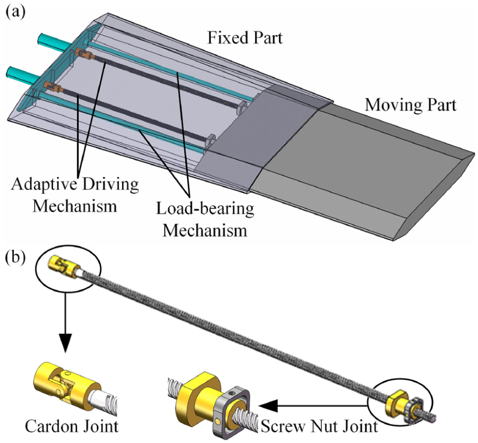
Conceptual drawings of the telescopic mechanism: (a) Schematic diagram of telescopic wing and (b) Design of adaptive driving mechanism.
The main principle of the adaptive mechanism is to add a Cardan joint at one end of the lead screw, and a rotating pair is added at the position of the screw nut. The adaptive mechanism guarantees that the two joints can deform and rotate at a certain angle in response to the occurrence of bending deformation. As a result, the screw does not bear radial loads, thereby protecting the screw, reducing the friction between the screw and nut, reducing the risk of sticking during the morphing process, and improving the reliability of the mechanism.
Load transmission analysis of adaptive driving mechanism
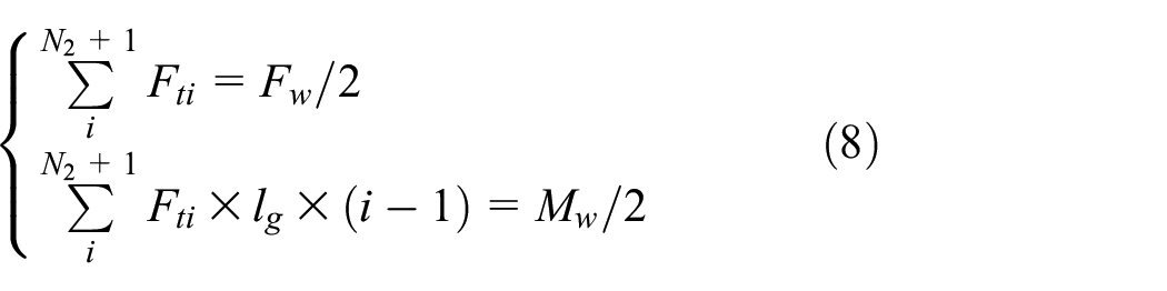
The load transmission analysis of the mechanism is conducted as shown in Figure 3. Assuming that the telescopic mechanism bears external loads

Kinematics model of the telescopic mechanism: (a) Overall kinematic model, (b) Cardon joint, and (c) Screw Nut Joint.
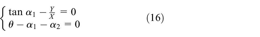
Compared with the aerodynamic load, the driving force is smaller, and its influence on the deformation of the wing is ignored in this model. The kinematic structure of a Cardan joint is a spherical four-bar RRRR linkage, as shown in Figure 3(b). Thus, the linkage transform matrix can be expressed as:

where the linkage parameter

And the closure condition for the mechanism is given by:

where
Then, given the axis angle
- reaction forces
- reaction moments
The lead screw is only subject to axial load, and the torque and axial force of the lead screw are shown in equation (4). Then, the reaction forces can be obtained by the static equilibrium of the links.


where p is the lead of screw,
The resistant action about the


Structural modeling of load-bearing mechanism
For the load-bearing mechanism, the deflection of the cantilever guide and external moment led to uneven contact force distribution. Assuming that the ball in this model can be treated as a compression-only spring with stiffness K and length d, and the slider is considered rigid. The summation of spring forces at each cross-section of the slider can express the contact force between the guide rail and the slider. The spring force vector is along the normal direction of the guide rail sliding groove. The ball contact diagram when the guide rail deformed is shown in Figure 4. The force analysis of the slider is carried out as follows:
In which

(a) Equivalent spring of slider ball and (b) contact force model of the load-bearing mechanism.
In Chained Beam-Constraint-Model (CBCM), the beam is discreted into several elements and each element is analyzed by BCM in succession.19,20 The proposed modified CBCM enables load application at arbitrary positions along the beam span. Through dynamic nodal position adjustment, the framework effectively simulates moving load conditions (Figure 5(a)). As this investigation focuses specifically on transmission capacity under large-deflection regimes, inertial effects associated with mass flow are neglected in the current formulation. These loads include forces and moments in two directions: tangential and normal to the deformed beam. The tangential force is generated by friction, while the normal force and moment are generated by aerodynamic load, which better captures the contact force conditions between the guide rails and sliders. The specific modeling method is as follows:

Modified chain beam model: (a) node partition of moving load and (b) loading state of single element.
Divide the beam into several segments. At the starting node of each segment, establish the local coordinate system, as shown in Figure 5. The node
The force analysis of the adjacent segments of the beam is shown in Figure 5(b).


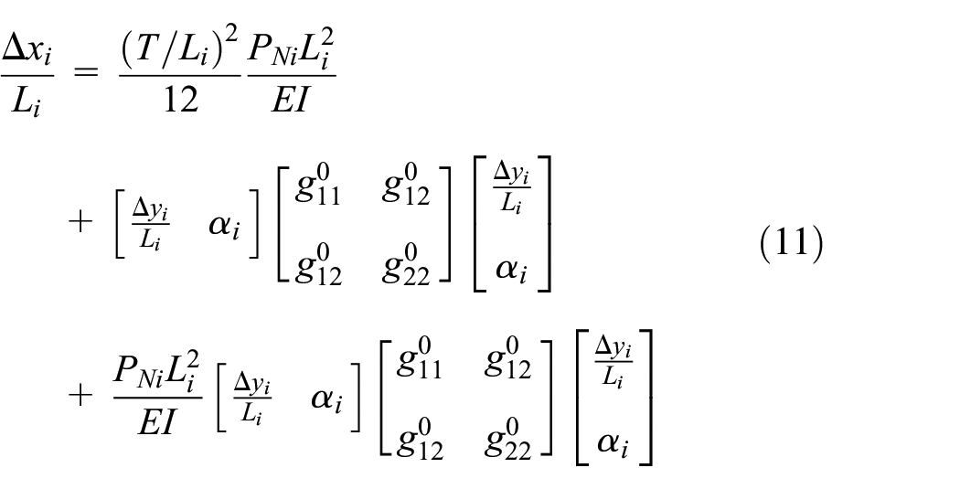
where
Since the slider is taken as rigid, the upper contact points of all slider balls are located in a straight line, and the lower contact points are the position of the contact node of guide rail. The equilibrium equation for the slider can then be written as follows.

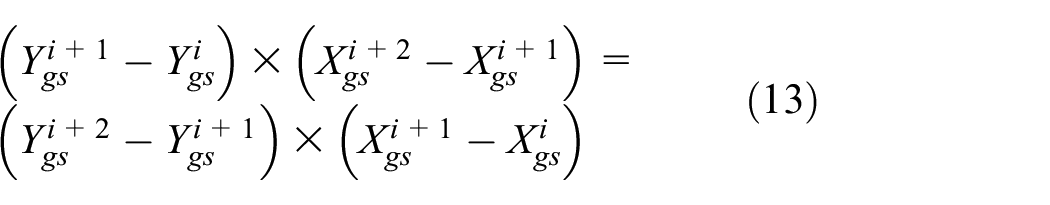
By solving equations (10)–(13) simultaneously, the displacements, rotations, and internal forces of each node in their respective coordinate systems can be obtained. And the global coordinates of each node are given by equation (14).

Where
Structural model of telescopic mechanism
Given the external force and external moment denoted as

Under the deformation of the guide rail, both the Cardon joint and the screw nut joint undergo specific rotations. This process involves a follower deformation, as illustrated in Figure 3. In the global coordinate system, there exists a corresponding geometric relationship, and two additional equations for the joint angles
Based on the above analysis, assuming the motor driving torque is T, we can simultaneously solve equations (4)–(7) and (10)–(14) to construct the structural model for the entire telescopic mechanism. This will allow us to calculate the required driving torque, the deformation of the guide rail, and the contact force between the guide rail and the slider.
Model verification
In this section, the telescopic adaptive driving mechanism prototype was developed to verified the adaptability of the designed mechanism. Through coordinated simulation and experiment, the accuracy of the theoretical model is validated.
Telescopic mechanism and experimental platform
The prototype consists of a telescopic mechanism and a driving device. The telescopic mechanism comprises cantilever guide rails on both sides and two sets of adaptive driving mechanisms. The driving device involves motors that transmit torque to the universal joint through a coupling shaft. The coupling shaft is a stepped shaft with angular contact ball bearings on both ends, preventing the axial force of the screw from directly affecting the motor during the telescopic process. The specific components and the block diagram for the proposed control scheme are illustrated in Figure 6. The loading arms are fixed on both sides of the telescopic plate, enabling the application of force and torque by suspending weighted objects of different masses. Multiple loading points are arranged on the loading arms on both sides, allowing for adjustment of the magnitude of the torque borne by the mechanism by altering the position of the suspended weights. The relevant parameters of the mechanism are presented in Table 1.

(a) Experimental setup and (b) control scheme.
Parameter of telescopic mechanism prototype.

Morphing test
As depicted in Figure 7, the morphing test platform employs various weight loads ranging from 0 to 40 kg on different loading positions of the loading arms. Then, the prototype is maneuvered to extend and retract by the motor-driven mechanism. Simultaneously, a torque sensor is positioned between the motor and the coupling shaft, and a data acquisition system is utilized to capture and interpret the sensor signals, thereby enabling the measurement of the driving torque of the mechanism.

Morphing test platform.
The motor completes 100 revolutions, extending the length by 500 mm. By setting the rotation speed to 1 rps, the reduced operational velocity helps mitigate the impact of factors such as rail vibration and the swinging of heavy objects on the driving force. The experimental results are as follows.
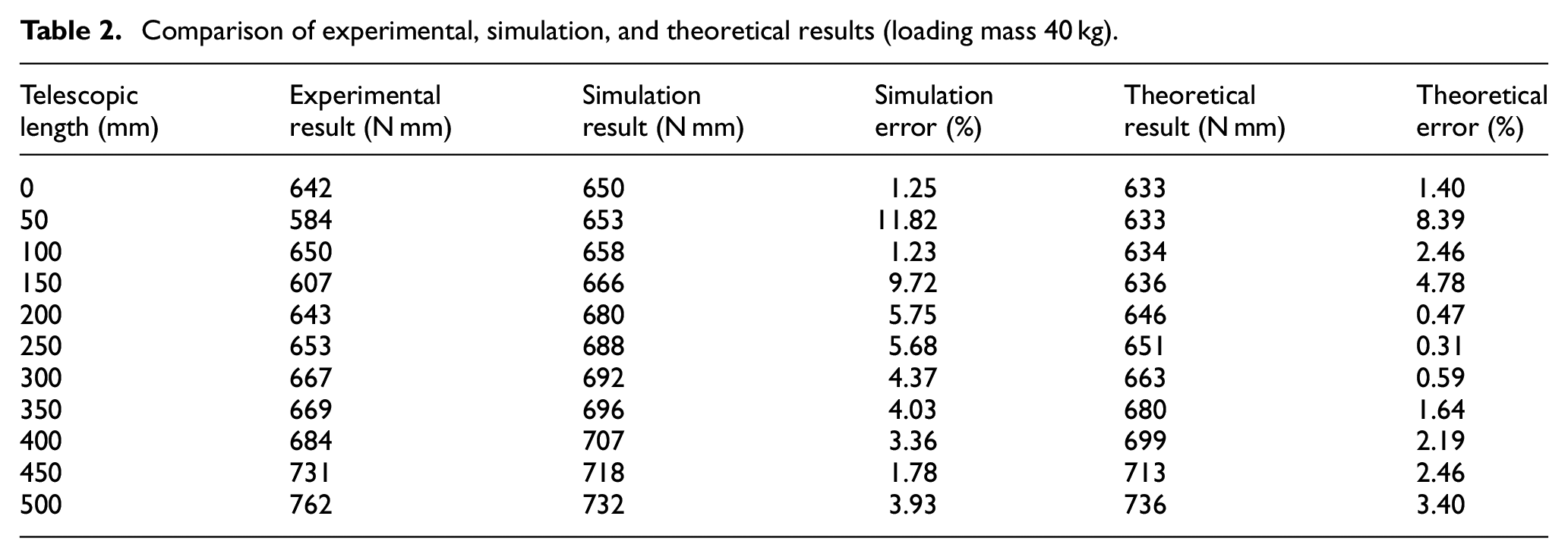
Figure 8 illustrates the driving torque during the motion process of the mechanism under different loads with lever arm length 250 mm. Table 2 shows the driving torque comparisons between experimental, simulation, and theoretical results under 40 kg loading mass. As the deflection increases, the transmission efficiency of the mechanism decreases, and the required driving torque increases. Figure 9 depicts the maximum driving torque under different loads. It is evident that the bending moment has a significant impact on the driving force. Due to the relatively short length of the slider, there is a substantial contact force at slider edge to balance the bending moment, leading to an increase in the required frictional force for driving. The telescopic experiments successfully demonstrated repeatable extension-retraction cycles under 40 kg payload conditions, confirming the adaptive driving mechanism’s operational reliability. The system maintained smooth motion transmission without sticking, while accommodating tip deflection up to 91 mm (

Measured and predicted driving torque (lever arm length 250 mm).
Comparison of experimental, simulation, and theoretical results (loading mass 40 kg).

Measured driving torque with different load.
Static load test
The morphing test platform is shown in Figure 10. Suspension rings were set on the top of the telescopic plate, and weights were suspended via pulleys and ropes to apply a vertical upward force to the telescopic plate. Adjusting the weights of the suspension rings and the loading arm enabled control over the external force and moment. By utilizing a motion acquisition system, the bending deformation of the gauge point of the guide rail was measured when the prototype was extended to 500 mm. Eleven tests were conducted, applying an external torque of 125 Nm and external forces ranging from 20 to 90 N. The scatter plot of the bending deformation under different loading conditions is compared with the results of the modified CBCM, as shown in Figure 11. The maximum theoretical and experimental result discrepancy is 6.81%, validating the accuracy of this method in predicting the bending deformation of the guide rail.

Static load test platform.

Guide rail end deflection.
Conclusion
This article introduces a novel telescopic mechanism capable of accommodating the deformations of high aspect ratio variable-geometry wings. This mechanism effectively shields the lead screw from the effects of alternating radial loads and avoids mechanism stagnation.
The structural model of the whole mechanism is established. By introducing an modified CBCM, the flexibility of the cantilever guide rail is considered. The contact force model between sliders is proposed. The model prediction accuracy is verified through experiment. The results show that the mechanism can achieve smooth telescopic movement with the wingtip displacement is 18% of the wing span. The bending moment has a significant impact on the driving force. And with the increase of wing deflection, the transmission efficiency of the mechanism decreases and the required driving torque increases.
Experimental observations revealed a positive correlation between wing deflection magnitude and mechanism oscillation amplitude, suggesting dynamic coupling effects. Future work will focus on developing a comprehensive dynamic model of the complete telescopic wing system, integrating both the flexible skin structure and transmission mechanism. This model will be experimentally validated, with particular emphasis on quantifying the adaptive mechanism’s influence on system dynamics under realistic aerodynamic loading conditions.
Footnotes
Handling Editor: Sharmili Pandian
Funding
The author(s) disclosed receipt of the following financial support for the research, authorship, and/or publication of this article: The authors gratefully acknowledge the support of National Natural Science Foundation of China (NSFC) through grants No. 52192633, 92471301, U2341237, T2388101, and 92471202, China Postdoctoral Science Foundation (No. 2023T160168).
Declaration of conflicting interests
The author(s) declared no potential conflicts of interest with respect to the research, authorship, and/or publication of this article.