
Abstract
This review examines various strategies to enhance the energy efficiency of roller bearings by reducing frictional torques from multiple sources: roller rolling resistance, sliding friction at roller ends, lubricant agitation, interactions with bearing cages, and frictional losses in seals. The review shows that recent advancements emphasise the significance of design variables, lubrication strategies, and geometrical optimisations. Surface roughness, precision coatings, oil flow alternations, and bearing geometry also significantly influence frictional torque. This review highlights the potential for significant reduction of frictional torque through the implementation of energy-efficient seal designs as well as the importance of precise friction torque measurement methodologies. These insights underscore the need for ongoing research and development to further improve roller bearing efficiency and reliability across various applications.
Introduction
Friction is a key performance parameter in bearings, and developing bearings with lower friction torque is crucial for enhancing energy efficiency and sustainability in mechanical systems. Beyond contributing to the global decarbonisation effort, energy-efficient bearings offer substantial economic benefits, such as reducing operational costs, extending equipment lifespans, and improving system reliability. These advantages translate into minimised maintenance, reduced downtime, and enhanced productivity across various industries. In the transportation sector, energy-efficient bearings are essential for optimising fuel efficiency and meeting environmental standards in railways, automotive systems, and aviation. Similarly, in renewable energy applications, such as wind turbines and solar trackers, reducing frictional losses in bearings directly enhances energy output and system longevity. Industries like mining, construction, and manufacturing also benefit from energy-efficient bearings, which lower operational costs and improve the sustainability of heavy machinery. By addressing both environmental and economic challenges, energy-efficient bearing technologies align with global sustainability goals, including the United Nations Sustainable Development Goals (SDGs). Specifically, these innovations contribute to Affordable and Clean Energy (SDG 7) and Industry, Innovation, and Infrastructure (SDG 9). Consequently, energy-efficient bearings have emerged as a cornerstone of sustainable engineering practices across a wide range of applications.
A wide range of approaches can be used to achieve energy-efficient bearing designs. These include but are not limited to light weight designs, load distribution improvements, thermal management, and friction reduction. This paper focuses on frictional torque reduction only. It directly improves energy efficiency by minimising the resistance encountered during operation. In addition, it also helps to achieve reduced wear that leads to longer operational lifespan and reduced operational costs.
According to SKF, frictional torque can be roughly estimated using the coefficient of friction as expressed by. 1

where M is the total frictional torque, µ is the coefficient of friction for the bearing type, P is equivalent dynamic bearing load, and d is bearing bore diameter. To obtain a more accurate result, the frictional torque is divided into load-independent torque and load-dependent torque as represented by 1 :

where

where

Various friction torque components of tapered roller bearing 2 (permission obtained).
At low speeds, the oil film formation is insufficient, and the torque is primarily dominated by M2 . As rotational speed increases, an oil film forms, transitioning the system to hydrodynamic lubrication, which significantly reduces M2 . The rolling resistance (M1 ) is generated by both elastic hysteresis loss (due to material deformation) and viscous rolling resistance (oil-induced rolling friction). However, the latter predominates, causing torque to increase as rotational speed rises, like the agitating resistance (M3 ). Sliding resistance (M4) is often significantly small when compared with other factors, therefore it is often ignored.
To enhance the efficiency of roller bearings, it is necessary to reduce the frictional torque or moment from all four sources. Therefore, this review will summarise methods to reduce: (1) Frictional torque due to rolling resistance between rollers and raceways. (2) Sliding fictional torque from the inner rib-roller end interfaces. (3) Agitating resistance of the lubricant. And (4) Frictional torque due to sliding between rollers and the cage. Moreover, the review will also discuss (5) techniques to reduce frictional torque in the seal, as well as (6) the methodologies used for measuring bearing frictional torque. While existing studies have explored friction reduction in roller bearings, most focus on isolated factors such as lubrication strategies or material coatings. This review uniquely consolidates insights across multiple friction sources. This review serves as a comprehensive resource for both academic and industrial audiences, addressing the broader challenges of energy efficiency and sustainability in bearing design. Such knowledge aids engineers, researchers, and industries in identifying effective solutions to improve mechanical system performance, reduce energy consumption, and minimise maintenance costs. Furthermore, this review can directly support global decarbonisation efforts by emphasising the role of energy-efficient bearings in lowering emissions across sectors like transportation, renewable energy, and manufacturing. By facilitating the adoption of low-friction bearing designs.
Specifically in the rest of this paper, Section “Reducing rolling resistance between rollers and raceway” outlines the fundamental principles of frictional torque in roller bearings, discussing key contributing factors such as rolling resistance, sliding friction, lubricant agitation, and seal friction. Sections “Reducing frictional torque (sliding torque) between inner rib and roller ends,”“Reducing agitating resistance of lubricant,”“Reducing frictional torque (sliding resistance) between rollers and cage,”“Reducing frictional torque in the seal,” and “A summary of friction torque reduction” provide a detailed review of various friction reduction strategies, including rolling resistance optimisation, lubrication techniques, advanced coatings, geometric modifications, and seal improvements. Section “Measurement methodology of friction torque for rolling bearing” examines the methodologies used for measuring frictional torque in bearings, highlighting experimental setups and computational approaches. Section “Future research directions” presents the directions for future research. Finally, Section “Summary” summarises this paper.
Reducing rolling resistance between rollers and raceway
This section examines key strategies for minimising rolling resistance in roller bearings. These include number of rollers, oil file thickness, bearing internal geometry, lubrication additives, roller geometry, hollow rollers, and roller sizes.
Number of rollers
Lee et al. 3 numerically (using the software BearinX) and experimentally investigated the efficiency of tapered roller bearings for an automatic transmission by varying two design variables: the number of tapered rollers and the roughness of the sliding contact surfaces. The study found that reducing the number of tapered rollers in the bearing significantly lowered the rolling resistance between the rollers and the raceway (see Figure 2). It illustrates the variation of calculated frictional torque in a tapered roller bearing as a function of shaft speed under different numbers of rollers. The results also indicate that as shaft speed increases, the frictional torque rises across all configurations, suggesting that higher rotational speeds amplify viscous rolling resistance, which dominates frictional losses in the bearing system.

Variation of calculated frictional torque using BerinX software with shaft speed under different numbers of rollers 3 (permission obtained).
Oil film thickness
The primary aim of lubrication in rolling bearing is to prevent direct contact between the rolling elements and the bearing raceways by forming a lubricant film. If direct contact occurs between surface roughness protrusions (i.e. metal-to-metal contact), the contact stress will be high, leading to heavy surface wear and material damage. These can be as seizure, premature peeling, and a reduction in fatigue service life. 2 The film parameter, Λ, can be calculated using equation (4) for the case of metal-to-metal contact.

where h0 indicates thickness of the lubrication film, and σ1 and σ2 indicate roughness of rolling elements and raceways respectively by using root mean square (RMS). When Λ > 3, the two surfaces are always separated by lubricant film (no metal-to-metal contact). Cases when Λ is smaller than 3 indicate interference between asperity tips, whilst cases for Λ < 1 indicate two parts will have very high probability to be in metal-to-metal contact.
Rolling friction is much lower than sliding friction, typically about 1/10–1/1000 of the latter magnitude. During rolling, under elastohydrodynamic conditions, the pressure distribution is asymmetrical, leading to viscous rolling resistance. This resistance generated from viscous rolling is significantly larger than resistance generated from pure rolling, and the former takes up the most of the frictional torque in roller bearings. The viscous rolling resistance can be calculated as 4 :

where
Equations (4) and (5) assume sufficient lubricating oil in the contact zone. However, if oil starvation occurs, both the film thickness and rolling resistance decrease, with oil starvation having a more significant influences on rolling resistance generated from vicious rolling than on film thickness. Maintaining adequate film thickness by controlling lubricating oil flow can help reduce frictional torque.2,4
In tapered roller bearings, frictional torque can be calculated as:

where B indicates an internal geometrical parameter of the specific bearing design, ϕ
T
is a factor to quantify the thermal reduction, N indicates rotation speed of the inner ring, η0 indicates oil viscosity, α0 indicated the pressure viscosity coefficient, F
a
is axial load, µ is the rib-end CoF, e is rib-to-roller height,
Bearing internal geometry
Based on the experimental results and elastohydrodynamic lubrication (EHL – a type of thin oil film lubrication), theoretical calculations as set out by equations (7) and (8) have been proposed for calculating torque of tapered roller bearings. 2


where z is the number of rollers, dm is the roller pitch circle diameter, DW is the mean roller diameter, LWR is the roller effective length, γm is DWcosθ/dm, α is the outer raceway angle, f(α) is the coefficient for effect of the contact angle, ϕ ci is the inner raceway crowning correction coefficient, ϕ co is the outer raceway crowning correction coefficient, and k1 to k8 are constants.
The effect of bearing internal geometry, roller effective length (LWR), number of rollers (z), contact angle (a), roller pitch circle diameter (dm), and raceway crowning radii (RCo and RCi) on friction torque are shown in Figure 3. The results show that bearing frictional torques increase with all studied parameters. The calculated values using equations (7) and (8) are quite consistent with experimental results. 2 The effect of bearing internal geometry on efficiency and load capacity are shown in Figure 4. From Figures 3 and 4 it is recommended that, for a low torque bearing design, contact angle and mean roller diameter should be large and the number of rollers and roller effective length should be small.

Effects of internal geometry of various bearing designs on friction torque 2 : (a) roller length, (b) number of rollers, (c) contact angle, (d) pitch circle diameter, (e) outer crowning radius, and (f) inner crowning radius (permission obtained).

Effect of internal geometry on efficiency and load capacity 2 : (a) efficiency and (b) capacity (permission obtained).
Lubrication additives
Bercea and Bercea 7 experimentally measured the frictional torque between the tapered roller and outer ring using different lubricating oils. They added 0.5%, 1.0%, and 2.0% low-density polyethylene (PE) to a base oil (H9) to examine its effects on frictional torque. The study found that the addition of 0.5% PE significantly reduced frictional torque by about 60%. Additionally, it was revealed that the frictional torque in the presence of the base oil alone was very sensitive to temperature, as shown in Figure 5(a). However, adding PE to the mineral oil reduced the temperature sensitivity of frictional torque within the studied temperature range, as shown in Figure 5(b). The polymer additive significantly reduces friction by forming a film of adsorbed macromolecular coils on the solid surface. The formation of this tribo-film depends on the additives added to the mineral oil. Lubricants with similar physical properties may result in different frictional torques depending on the loading conditions.8,9

Comparison of friction torque between: (a) base oil and (b) with 0.5PE with bearing speed at different temperatures (°C) 7 (permission obtained).
Roller geometry
The operation of tapered roller bearings (TRBs) involves complex interactions between the rollers and the raceways, significantly influencing their performance and lifespan. In this context, geometric homogeneity (consistency) of the rollers plays a critical role. Research has shown that raceway surface waviness10–12 and geometric errors 13 significantly impact the friction torque in bearings. In this context, Liu et al. 14 proposed a quasi-static model and a friction torque model for TRBs, focusing on the geometric homogeneity of the rollers. This homogeneity is characterised by the deviation in roller diameter and the distribution pattern of the rollers.
Figure 6 shows the variation in contact force between each roller and the outer raceway when the roller diameters are adjusted according to the specifications in Table 1. The results highlight the impact of roller diameter deviation and distribution patterns on contact force distribution in tapered roller bearings. In Figure 6(a), when rollers with diameter deviations are randomly distributed, the contact forces vary significantly, leading to uneven load distribution. In Figure 6(b), organising rollers by deviation size improves uniformity, reducing peak contact forces. Figure 6(c) represents the positional arrangement of rollers. Both the roller diameter deviation and the distribution pattern significantly affect the uniformity of the contact force distribution and the maximum contact force. 14 Figure 7 illustrates the friction torque acting on the inner and outer rings, indicating that the geometric homogeneity of the rollers leads to a decrease in the friction torque on the rings. The friction torque on the outer ring is solely due to the rolling friction between the rollers and the raceway. In contrast, the friction torque on the inner ring arises from both rolling friction and flange interactions. 14

Effects of the geometric homogeneity of rollers on contact force distribution of TRBs: (a) rollers with a diameter deviation are randomly distributed, (b) rollers with a diameter deviation are distributed by deviation size, and (c) schematic diagram of the position angle of the jth roller 14 (Open Access – CC BY 4.0).
The generating data of diameter deviation value ΔD. 14


Effects of the geometric homogeneity of rollers on friction torque acting on rings: (a) friction torque acting on inner ring and (b) friction torque acting on outer ring 14 (Open Access – CC BY 4.0).
Furthermore, the interactions between these parameters necessitate a thorough understanding of their combined effects. Optimising the geometric configurations can lead to enhanced performance and reduced wear in TRBs, emphasising the importance of precision engineering in the design of bearing systems.
Acar et al. 15 optimised the roller and ring raceway profiles of an existing cylindrical roller bearing (CRB), model NJ 309 EP4, to improve its energy efficiency. The primary goal was to minimise the friction torque while maintaining the bearing’s fatigue life. The crown heights of the roller profile and the radius of the raceway camber profile (RCP) were selected as design variables. The study also investigated the effect of variations in the radius of the raceway camber profile on friction torque and fatigue life. Numerical modelling was carried out using CAD and ANSYS software, and the results were experimentally validated using a bearing test rig to measure the friction torque and fatigue life.
The numerical simulation revealed that the configuration with a maximum crown height (MCH) of 1.82x and a raceway camber profile (RCP) of 2.20z resulted in a lower friction torque as illustrated in Figure 8(a), while it slightly reduced fatigue life as shown in Figure 8(b). This configuration was used in the redesigned bearing, designated as NJ 309 OP. Experimental tests on the friction torque of the redesigned bearing showed a 29.1% reduction compared to the base bearing, while the redesigned bearing exhibited only a 3% decrease in fatigue life. 15

Variation of: (a) friction torque and (b) fatigue life with respect to the maximum crown height, MCH (RCP 1/2 this value is kept constant) redrawn from Acar et al. 15
Hollow rollers and roller size
The implementation of hollow rollers in large-size bearings, particularly those used in wind turbines, showed that friction between the rollers and the raceway was significantly reduced, and stress distribution became more uniform at the ends of the rollers.16,17 It has been demonstrated that approximately 26% energy savings are possible with the use of bearings with hollow rollers. 17
Despite previous findings, 17 Mármol 18 found that the new geometry failed to outperform traditional tapered roller bearings (TRBs) under high axial loads. Later discussions will show that these differences could stem from the specific application environments; hollow rollers are more effective in systems with predominantly radial loads but may exhibit higher deformation under axial stress. Further investigation into material properties and load distribution mechanisms is required to validate their performance under diverse conditions. Mármol 18 investigated the effects of internal geometrical parameters on the contact between the roller and raceways of a TRB. By analysing correlations between different geometrical parameters, a new type of rolling bearing was proposed that eliminates the need for rib contact. A Multi-Body Simulation (MBS) model was used to simulate the behaviour of this proposed bearing, and experimental investigations were carried out using a prototype bearing with optimised geometrical parameters to validate the modelling results. Table 2 outlines the parameters of the prototype bearing.
Parameters defining the geometry of the prototype.

Based on the sensitivity analysis, the following effects of geometrical parameters on performance were reported: The contact length affects load capacity, frictional torque, and maximum pressure. A longer contact length increases load capacity but also raises frictional torque while reducing maximum pressure. The contact length is, in turn, influenced by the roller’s geometry: a narrower osculation (κ) leads to a longer contact length, while a larger contact angle (α) relative to the load angle results in a shorter contact length. The roller’s crowning significantly affects drilling friction, which is the frictional torque generated by the roller’s rotation around its own axis as it rolls along the raceway, and it also impacts overall frictional torque. Axial displacement can be minimised by reducing profile curve radius (PCR) and increasing the roller length. Despite these findings, the new bearing geometry failed to outperform traditional TRBs under high axial loads. When tested on the axle-gearbox of heavy-duty trucks, the new bearing design exhibited higher frictional losses than the TRB, proving unsuitable for this application. 18
Reducing frictional torque (sliding torque) between inner rib and roller ends
The sliding torque between raceway inner ribs and roller ends is significantly influenced by surface roughness and geometric parameters. By optimising these factors, such as reducing surface roughness and adjusting roller geometry, engineers can achieve substantial reductions in frictional torque. Surface treatments and advanced coatings further contribute to minimising friction, enhancing the efficiency, and improving the longevity of bearings, especially under high-load and boundary lubrication conditions.
Analytical calculations, as shown in Figure 9, indicate that the frictional torque was significantly reduced when the roughness Ra of the roller surface was decreased from 1 to 0.30 µm, with this reduction being more pronounced at lower shaft speeds. 3 When incorporating both surface roughness and the number of rollers into the analysis, it was found that a surface roughness of 0.3 µm and 20 rollers resulted in the minimum frictional torque. Under these optimised conditions, the frictional torque was significantly reduced by approximately 65% for the left bearing and 57% for the right bearing. The researchers also compared the calculated results with experimental data and found a very good agreement between them, as illustrated in Figure 10, 3 confirming that the proposed model accurately predicts the effects of surface roughness and roller count on frictional torque, validating its applicability for optimising bearing design.
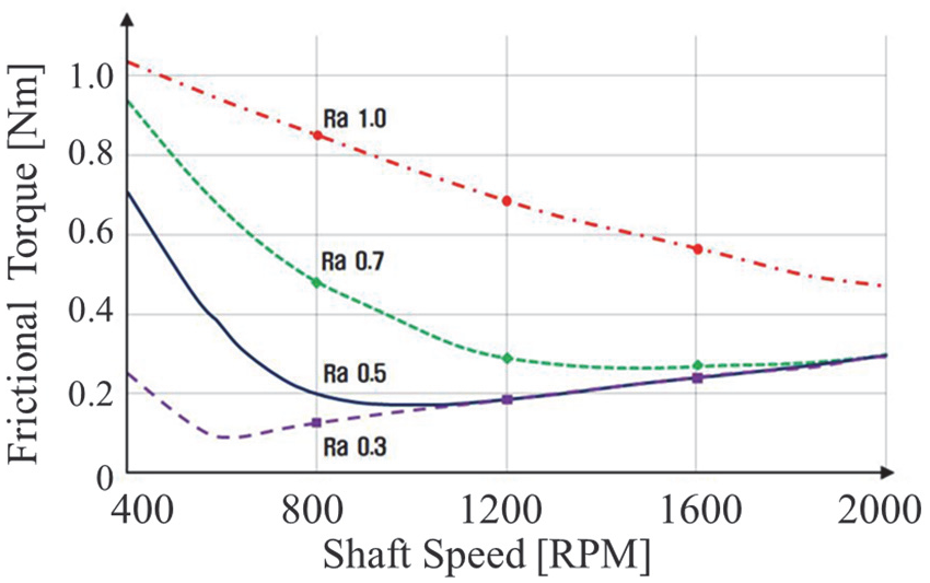
Effect of surface roughness shaft speeds on frictional torque 3 (permission obtained).
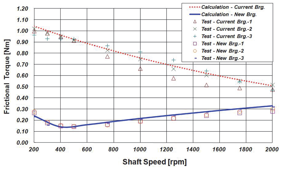
Comparison of calculated and measured frictional torques 3 (permission obtained).
In efforts to enhance the energy efficiency of tapered roller bearings, Wirsching et al.19,20 numerically investigated the macro-geometric parameters of contacting pairs. The TELOS 5.0 software tool was used to perform a quasi-static, isothermal, lubricated contact simulation incorporating a non-Newtonian rheology model. For simple geometric pairings, such as sphere/cone contact, the lowest coefficients of friction were achieved with larger radii. Conversely, for more complex geometries, the global optimum often lies within the mid-range of the radius parameters, as observed in a torus/torus configuration. In these cases, eccentricity had a lesser influence on the parameters. 20
The study also revealed a trade-off between high load-carrying capacity and low frictional loss. Spherical or toroidal geometries on the roller end face with a large radius, paired with a tapered (cone) rib geometry without curvature, were found to be advantageous for reducing frictional losses (Figure 11). 19 On the other hand, spherical or toroidal rollers on toroidal rib geometries with medium radii were better suited for achieving larger lubricant film heights and higher load-carrying capacity. 19

Evaluation of the optimisation results: (a) the minimal lubricant gap and (b) the COF, with the different optimisation targets minimising the COF and maximising the lubricant gap of all geometry pairings 19 (Open Access – CC BY 4.0).
Precision powder shot peening and Shot Machine A. one Polish (SMAP) 21 treatments were performed on the large flange surface of the inner ring to reduce the sliding friction between the roller face and the flange surface of tapered roller bearings. 22 Figure 12 presents the measured torques for the bearing with the original and different shot peening-treated flange surfaces under the conditions listed in Table 3. The torque of the SMAP-treated bearing was less than that of the product on the market, and the reduction in torque due to running-in occurred earlier. This indicates that the dynamic torque of the tapered roller bearing can be reduced about 50% by precision powder shot peening and SMAP treatment of the large flange face of the inner raceway. 22
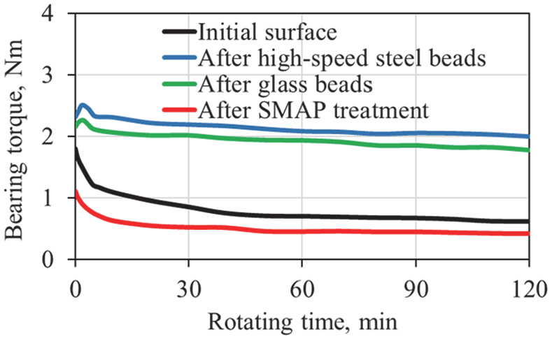
Change in torque for shakedown of tapered roller bearing. SMAP: Shot Machine A one Polish redrawn from Noguchi et al. 22
Conditions for measuring torque of tapered roller bearing.

Doll 23 applied nanocomposite coatings consisting of nanocrystalline metal carbides embedded in amorphous hydrocarbon or carbon matrices (MC/aC:H or MC/aC) to rolling element bearings.24,25 Using the Zhou and Hashimoto 26 formula for the relationship between the measured torque and dimensionless parameter λ, they demonstrated that a 7% increase in λ could reduce friction torque by 0.75 Nm per bearing This improvement in λ was attributed to the micro-polishing action of MC/aC:H coatings on roller bodies. 23 These coatings also enhanced fatigue life under boundary layer lubrication, improved debris tolerance, prevented false brinelling, increased operational speed, reduced friction, and provided oil-out protection for rolling element bearings. 23
Various other coatings, such as SKF’s and NSK’s DLC coatings, 27 manganese phosphate coatings, 28 CrAlN and ZrCg coatings, 29 and Ti–MoS2 coatings, 30 have been shown to reduce friction and wear in roller bearings. In another study, Zhao et al. 31 replaced some steel rollers with ceramic rollers, observing that ceramic rollers reduced friction due to their higher elastic modulus, which effectively inhibited material spalling from plastic deformation at the friction interface. These findings suggest that different coatings and material choices can significantly reduce friction and wear in roller bearings.
Reducing agitating resistance of lubricant
Efficient lubrication is critical for the optimal performance of tapered roller bearings, as it reduces frictional torque and minimises wear. However, the movement of lubricating oil within the bearing assembly can lead to what is known as agitating resistance, a type of frictional resistance caused by the interaction of the oil with bearing components. Agitating resistance contributes to overall frictional torque, which can affect bearing efficiency and increase operating temperatures. In tapered roller bearings, the agitating resistance is linked to a “pumping action” that causes lubricating oil to move from the front to the rear of the inner ring.32,33 The movement of oil within the bearing is complex, influenced by the rotation of the inner and outer rings, the cage, and the rollers, 34 which collectively contribute to agitating resistance. To mitigate this resistance and reduce frictional torque, controlling oil flow into the bearing is essential. Rapidly discharging excess oil, particularly between the cage and the small rib of the inner ring, minimises oil buildup, thereby lowering the overall torque.2,4,6
Given the significant impact of oil flow on frictional torque, adjustments were made to the bearing design based on theoretical elastohydrodynamic lubrication (EHL) analysis. Specifically, the inner diameter of the casing was reduced, and the inner ring’s small rib was restructured into a labyrinth shape (Figure 13). This design change reduces the radial clearance (X1) between the cage and inner ring, which substantially affects both torque and oil flow. 35 By decreasing the X1/D (D is the inner ring bore diameter) ratio, the oil flow rate was reduced by 60% compared to conventional bearings, while torque was lowered by 30%, as shown in Figure 14. 2

Comparison between newly developed and conventional bearings 2 : (a) developed bearing, (b) labyrinth, and (c) conventional (permission obtained).

Ratio (developed/conventional) of torque and oil flow at difference radial clearance. Axial load = 4 kN, rpm = 3000 rpm and oil temperature = 50°C 2 (permission obtained).
In further testing, the researchers of Matsuyama 2 applied a labyrinth-like fixture to a conventional roller bearing, achieving a 40% reduction in torque (Figure 15(a)). However, this modification also led to a temperature increase of about 20°C, attributed to an 80% reduction in oil flow in the modified bearing. By contrast, the temperature rise in both the newly developed bearing and conventional bearing remained comparable, which was due to the large outer raceway angle in the new bearing design (Figure 15(b)).
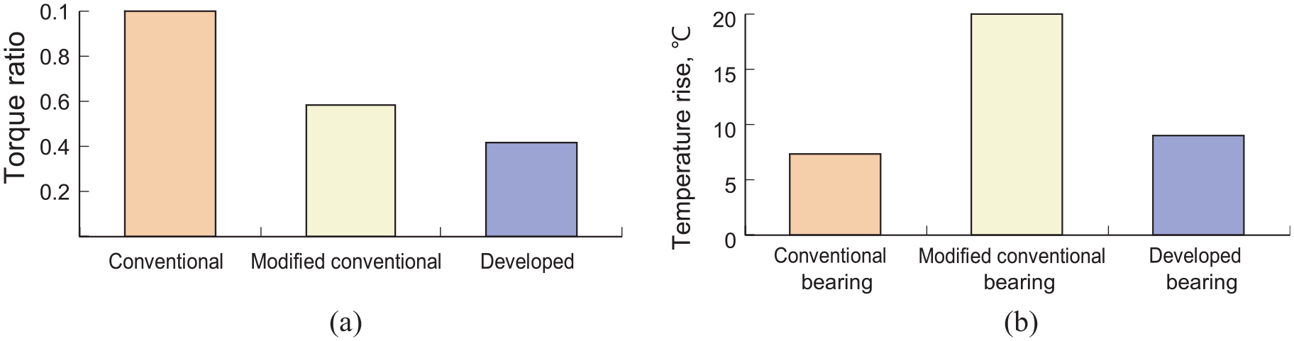
Comparison of performance between developed and conventional bearings 2 : (a) torque ratio and (b) temperature (permission obtained).
To deepen the understanding of agitation torque in bearings, Wen and Oshima 36 developed a ball bearing model using computational fluid dynamics (CFD) to simulate agitation torque caused by oil flow. Particle trace simulations demonstrated that oil flows circumferentially along the outer cage surface, identified as the main source of agitation torque acting on the metal cage. Based on this finding, they proposed flattening the cage’s uneven surfaces in the direction of rotation, leading to a new low-torque ball bearing design. This design concept was also applied to the rib side, where larger flat surfaces on the cage showed less force and effectively reduced agitation torque. Figure 16 illustrates the calculated and measured agitation torque for both conventional and new cage designs, under the conditions outlined in Table 4, revealing that the new design reduces agitation torque by approximately 30%. Similarly, Wang et al. 37 found that optimising the cage structure and reducing the roller half-cone angle lowered frictional torque by 29.1% and 26.2%, respectively.

Comparison of agitation torque. 36
Bearing frictional torque test conditions. 36

Reducing frictional torque (sliding resistance) between rollers and cage
The cage plays a critical role in maintaining proper spacing and facilitating lubrication for the rolling elements, thereby supporting smooth operation and stability.38,39 Although the cage contributes minimally to the overall bearing friction compared to other components, 40 its design has a pronounced effect on bearing dynamics and durability.41,42 This section highlights the effects of cage design modifications on sliding resistance, with a focus on factors such as pocket clearance, cage conformality, and temperature gradients.
Research has shown that optimising the cage pocket geometry and clearance can decrease friction, enhance lubrication, and improve bearing performance. 39 For instance, in experimental tests with a modified Bearing Cage Test Stand,43,44 along with theoretical analysis, Peterson et al. 39 reported that optimised cage designs reduce total bearing friction by approximately 8%. The research indicates that while reducing pocket clearance increases friction between the rollers and cage pockets,39,45 decreasing cage conformality lowers friction. 45 However, this reduction in conformality compromises the cage’s ability to retain oil, 45 highlighting the need for a balanced approach in cage design to minimise friction while maintaining lubrication.
To calculate energy losses in rolling bearings due to cage design, Gaydamaka et al. 46 employed a temperature gradient (temperature difference between bearing and environment) technique 47 and a frictional moment calculation method 48 to modernise bearing cage design. They 46 analytically calculated the pressing forces of the driving and driven rolling elements on the jumpers and proposed an improved cage design, as shown in Figure 17. The proposed modernised bearing cage consists of two rings (1) with cavities (2) and transverse partitions (3) matching the number of pockets (7). It also has partitions (4) with stepped protrusions (5). The distinguishing characteristic is that all sides of the seats (7) have a three-wave contour (6), with the convex surfaces positioned in the middle of the cylindrical surfaces and at the ends of the rollers. Additionally, two or more micro-indentations (8) are present on the friction surface (9) of the rings adjacent to each pocket. 46 The calculated heat generation for both the typical and modernised designs is shown in Figure 18. The modernised roller bearing cage design decreases the temperature gradient by 0.4°C–1.4°C compared to the conventional one.

The design of modernised cage 46 : (1) rings, (2) cavities, (3) transverse partitions, (4) partitions, (5) stepped protrusions, (6) a three-wave contour, (7) pockets/seats, (8) micro-indentations, and (9) friction surface (Open Access – CC BY 4.0).

The temperature gradients diagrams for a typical design of a cylindrical roller bearing (region R, z = 14) and a modernised one (region E, z = 16): curve 1 – Fr = 50 kN, V = 200 km/h; curve 2 – Fr = 30 kN, V = 100 km/h 46 (Open Access – CC BY 4.0).
Reducing frictional torque in the seal
Dindar et al. 49 classified the friction sources of a double-row roller slewing bearing into three main components: the bearing inner mechanism, the upper seal, and the lower seal. Test results indicated that 34.5% of the total friction is due to the bearing inner mechanism, while 54.8% is caused by the lower seal, and 10.8% by the upper seal. These findings highlight that over 65% of the total friction torque is attributed to the seals, with the lower seal contributing the most. The higher torque from the lower seal is due to the garter spring, which increases the contact force of the seal. As a result, good selection of the sealing elements is beneficial for reducing friction torque in slewing bearings.
Research has shown a strong interconnection between seal heat generation and the operating temperature of bearings. Seals designed for low torque and minimal heat generation significantly lower the operating temperature of the bearings.50,51 Moreover, enhancing contamination exclusion through improved designs can further mitigate bearing heating and set-outs. 50 Additionally, a seal’s ability to keep out water throughout the bearing’s service life is crucial for maintaining optimal bearing performance and preventing water etch damage. To address these challenges, Timken developed the EcoTurn labyrinth seal, which was rigorously tested in both laboratory and field conditions.50,52
The EcoTurn seal reportedly reduces operating torque by approximately 2.26 N m (20 inch-pounds) per bearing compared to its closest competitor 52 for rail freight applications. Additionally, the labyrinth seal reduces hot-box set-outs by providing a lower average operating torque and temperature compared to other commercially available seals, as shown in Figure 19. 52 The water spray test results, conducted according to seal specification M-959 (MSRP Section H), are summarised in Table 5, demonstrating the EcoTurn seal’s effectiveness in maintaining water exclusion. 50 The EcoTurn seal completely prevented water ingress (0% water retention), whereas the competitor’s seal allowed 22% water penetration into the bearing.
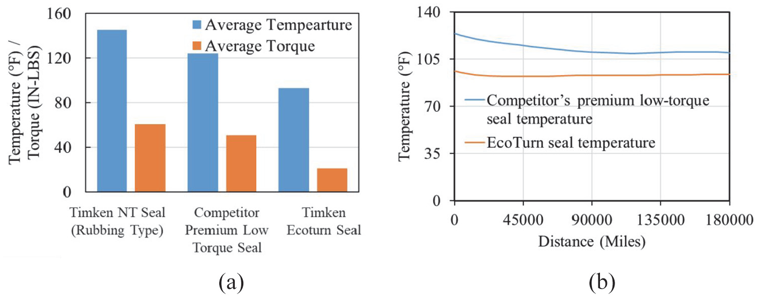
Comparison of generated temperature and torque of EcoTurn and a competitor’s seals: (a) temperature and torque and (b) temperature. Redrawn from Timken. 52
Water spray test results. 50

The EcoTurn seal was also used in a newly designed heavy haul journal bearing with a larger roller diameter (AP-2). The focus of the new design was to increase axle load capacities up to 45 tonne gross rail load (G.R.L). The AP-2 bearing was designed to fit within the same envelope as the existing “short” G bearing but features a different internal geometry to reduce bearing torque. 53
The AP-2 short G bearing was laboratory tested according to AAR Specification M-934 for a complete bearing assembly and the new-size EcoTurn seal. Specification M-959 was used for the seal-grease combination. 53 Two greases, namely “Grease A” and “Grease B,” were used in the tests. A comparison of the design data is shown in Table 6, with detailed differences available in Buchanan et al. 53 Laboratory test results are presented in Table 7. Following laboratory testing, the newly designed bearing was fitted to 10 wagons and Figure 20 depicts the in-service bearing temperatures of these wagons over time.
Comparison of additional design data for new and existing bearings. 53

Laboratory test details. 53


Bearing temperature data over time (this is normalised above ambient). Axles 1 and 2 use grease B; axles 3 and 4 use grease A redrawn from Buchanan et al. 53
The AP-2 design was also modelled using finite element method, together with the current axle as a complete wheelset to evaluate the theoretical performance of the wheelset system under loads of up to 45 tons G.R.L. The modelling accounted for speeds ranging from 50 to 80 km/h and included a dynamic application factor of 1.2 in the L10 life calculation. The finite element model shows that the lambda ratio (the ratio of fluid film thickness to the composite surface roughness of parts, 0.88), stress distribution on the raceway, fretting index (0.61), and bending stress on the bearing journal fillet at 45 tons G.R.L. are within acceptable ranges. 53 In addition, SKF54,55 developed a compact tapered bearing unit (CTBU) designed to reduce life cycle costs and extend maintenance intervals. The CTBU includes several features, such as new integrated low-torque seals and a polymer spacer. The SKF CTBU with SKF low-friction railway bearing seals reduces bearing friction torque by 13%, lowers bearing temperatures by 5°C, and enables 17% longer grease life. 56
A summary of friction torque reduction
Table 8 provides a comprehensive overview of various methods employed to reduce friction torque, energy consumption, or temperature rise reviewed in this paper. It highlights innovations across structural, material, and design domains, focusing on their effectiveness and additional observations.
Summary table on reported improvements.

The listed friction reduction strategies have broad applicability across multiple industries where improving bearing efficiency is critical for cost savings, operational performance, and sustainability. Some key industries that can benefit from these methods include:
Rail Transportation: Labyrinth seals (40% friction torque reduction) and EcoTurn seals (2.26 Nm torque reduction) are particularly beneficial in freight train journal bearings, where reducing friction lowers energy consumption and helps prevent overheating and failures in long-haul operations. SKF’s Compact Tapered Bearing Unit (CTBU), which achieves a 13% reduction in friction and a 5°C temperature drop, is already being used to enhance railway bearing efficiency and extend maintenance intervals.
Automotive Industry: Advanced coatings and optimised bearing geometries (e.g. polyethylene coatings with 60% friction reduction) improve fuel efficiency in electric and internal combustion engine vehicles by reducing energy losses in transmission and wheel hub bearings. Reduced surface roughness and rolling resistance optimisation in tapered roller bearings can extend the lifespan of vehicle drivetrains, reducing maintenance costs.
Wind Energy and Renewable Power Generation: Hollow rollers (26% energy savings) are particularly effective in wind turbine bearings, where they help reduce friction losses and improve energy output efficiency. Optimised lubrication strategies help minimise wear in slow-speed but high-load applications, such as hydroelectric power plant bearings.
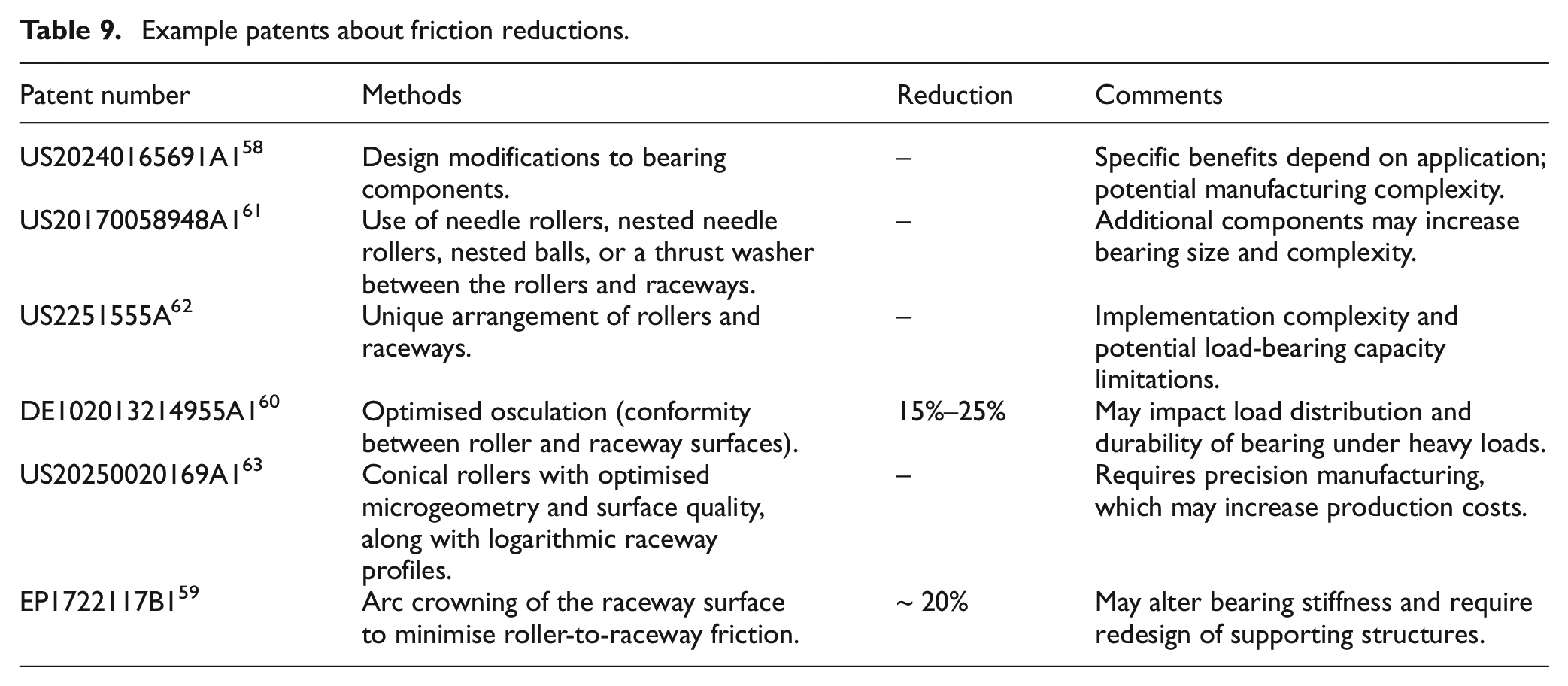
To reflect the applicability of the friction torque reduction methods, some example patents are listed in Table 9. And more recent patents on roller bearing can be found in a review journal article. 57 These involve various friction reduction strategies for tapered roller bearings, highlighting innovative approaches in bearing design, component modifications, and geometric optimisations. Some methods, such as needle rollers, nested balls, and thrust washers, 58 aim to minimise friction by altering internal bearing interactions, while others, like arc crowning of raceway surfaces 59 and optimised osculation, 60 focus on improving surface contact conditions. Reported friction reductions range from 15% to 25%, with some patents claiming significant but unspecified reductions. However, these approaches come with trade-offs, such as increased manufacturing complexity, potential durability concerns under heavy loads, and added production costs. These innovations provide valuable insights into advancing energy-efficient bearing technology while balancing performance trade-offs in real-world applications.
Example patents about friction reductions.
As mentioned previously, the listed methods are not without limitations. For example, advanced coatings, such as nanocomposite coatings and polyethylene additives, show significant friction reduction benefits (e.g. 60% with polyethylene 7 ). However, coatings like nanocomposites primarily improve fatigue life and debris tolerance but provide limited immediate frictional torque reduction (7%). 23 Additionally, coatings may incur higher manufacturing costs and require precise application processes, making them less suitable for cost-sensitive industries. Optimisations of maximum crown height and raceway camber profiles achieve a 29.1% reduction in frictional torque but at the cost of a 3% reduction in fatigue life. 15 This trade-off highlights the challenge of balancing torque reduction with durability, particularly in applications requiring extended operational lifespans. Similarly, hollow rollers reduce energy consumption by 26% but exhibit limitations under high axial loads, where deformation may compromise performance. 18 Labyrinth seals significantly reduce frictional torque (up to 40%) but lead to increased operating temperatures (20°C) due to reduced oil flow. 2 This temperature rise could accelerate lubricant degradation and reduce bearing lifespan. EcoTurn seals avoid these thermal drawbacks but may not be compatible with all bearing geometries or applications. 50
Measurement methodology of friction torque for rolling bearing
The frictional torque in rolling bearings is a critical parameter influencing the performance and efficiency of various mechanical systems. Understanding the factors that contribute to frictional torque is essential for optimising the design and functionality of these components. 64 Recent research has increasingly focused on energy-efficient bearing designs, resulting in the development of various measurement devices. This section provides an overview of the methodologies used to measure frictional torque in rolling bearings, categorising these measurement devices into three distinct types based on the method of load application: radial load, axial load, and combined load configurations, as illustrated in Figure 21. Among all bearing test rig, one of the most famous is the FE8 bearing test rig specific by the German industry standard DIN 51819. 64 It defines the FE8 test procedure for evaluating lubricating greases used in rolling bearings. This standard specifies the testing conditions, including load application (axial and radial forces), temperature settings, rotational speed, duration of testing, assessment of wear, friction, and lubricant degradation. The DIN 51819 standard ensures reproducibility and comparability of lubricant performance results across different testing laboratories and manufacturers. It is widely used in the automotive, railway, and industrial machinery sectors to certify grease suitability for demanding applications.

Bearing test rig types.
The FE8 test is a standardised bearing test method used to evaluate the friction, wear, and lubricant performance of rolling bearings under defined operating conditions. It is commonly used for testing lubricant properties in high-load applications, such as railway bearings, industrial gearboxes, and heavy machinery. The test applies axial and radial loads to rolling bearings while continuously measuring friction torque, temperature, and wear. It is particularly relevant for evaluating greases and lubricating oils in bearings subjected to extreme loads and mixed friction conditions. The FE8 test typically involves tapered roller bearings or cylindrical roller bearings, with the test duration and parameters specified depending on the lubricant or bearing material being evaluated. Other industry standards for bearing tests are also available as listed in Table 10.
Bearing test standards.

Test rigs for radial load condition
Radial load test rigs are commonly used to investigate bearing performance under radial load conditions. Mabie 73 developed a high-speed torque tester designed for measuring torque across various types of bearings. In this setup, torque measurements were obtained by monitoring the angular displacement of a torque disk attached to the outer race of the test bearing, while the inner race was driven by a shaft connected to an air turbine. The torque disk displacement was measured using strain gauges mounted on a cantilever beam, which converted mechanical deflection into an electrical signal for further analysis. Additionally, a variable-reluctance transducer tracked the rotational speed of the test bearing by generating a voltage proportional to the shaft speed. Data from the strain gauges and transducer were then analysed to understand the relationship between torque and speed. It is noted that this method is limited by its sensitivity to temperature variations and potential signal noise from high-speed operation, which must be accounted for in the data interpretation.
Test rigs for axial load condition
Axial load test rigs are designed to evaluate bearing behaviour under purely axial loading conditions. Manjunath et al. 74 employed a vertical-shaft roller-bearing tribometer (RBT) to study heavily loaded EHL line contacts (2–3 GPa) in tapered roller bearings (TRBs) under pure axial load, ensuring uniform contact across all rollers. The RBT system used a hydraulic cylinder to apply axial loads, while a strain-gauge-based load cell measured torque at different speeds. The lubricant viscosity and film thickness were recorded throughout the experiment to assess their influence on torque. However, one limitation of this setup is that it assumes uniform lubricant distribution, whereas real-world conditions may involve localised starvation effects, which were not considered in the study. A cross-section view of the RBT is shown in Figure 22. The setup comprises six subsystems: drive unit, support-bearing unit, test-bearing unit, hydraulic loading unit, oil circulation unit, and control unit. A hydraulic cylinder applies axial loads, with frictional torque measured via a lever arm and load cell, adjustable to accommodate anticipated friction forces and required accuracy levels. 75 The RBT supports both forced circulation and oil bath lubrication, providing precise control over oil flow and temperature. Thermocouples monitor temperatures at the supply oil inlet (SOI), supply oil outlet (SOO), and the TRB outer race, with data continuously recorded throughout testing.
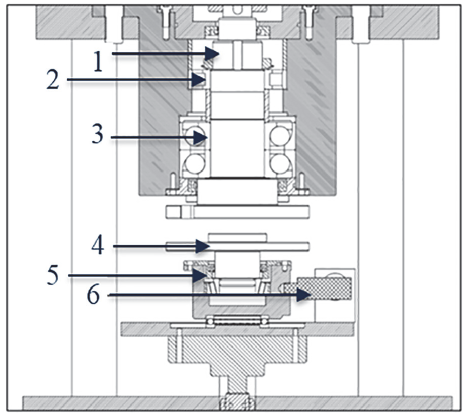
Cross-sectional view of the RBT: (1) Main shaft; (2) Cylindrical roller-support bearing; (3) Angular contact ball-support bearing; (4) Test-bearing adapter; (5) Test-bearing housing; (6) Measuring lever arm 74 (Open Access – CC BY 4.0).
Test rigs for combined load conditions
Combined load bearing test rigs offer versatility, as they can apply axial, radial, or combined axial and radial loads. Li et al. 76 used a combined load roller bearing testing setup to verify their friction torque calculation method. The setup consists of a servomotor, a torque meter, a radial loading device, an axial loading device, and two TRBs, as shown in Figure 23. The servomotor provided rotational input at controlled speeds, while radial and axial loads were independently applied using hydraulic actuators. Torque was measured using a high-precision torque transducer, which accounted for variations in rotational speed and loading conditions. However, a limitation of this method is that thermal effects on bearing torque were not explicitly measured, which may influence torque values under prolonged operation. The setup lacks an output device, so the input torque represents the combined friction torque of the two TRBs. Since both TRBs operate under identical conditions, the friction torque of a single TRB is half of the total friction torque measured by the setup.

Experimental setup to measure the friction torque of the TRB: (a) schematic diagram and (b) physical diagram 76 (permission obtained).
Mármol 18 developed new geometries for a rolling bearing and studied its behaviour using multi-body simulation (MBS). To validate the MBS results, the author conducted experimental tests using a frictional torque test rig developed by Aul.77,78 A schematic diagram of the rig is presented in Figure 24, illustrating the main components (black), movements (green), and loads (red). The setup comprises three main modules: test, loading, and tilting modules. In the test module, the outer ring of the rolling bearing under examination (test bearing) is housed within the inner ring of a hydrostatic bearing. The outer ring of the hydrostatic bearing is fixed to the base plate, allowing the generated frictional torque in the test bearing to be effectively transferred to the inner ring of the hydrostatic bearing. The rotational degree of freedom of the hydrostatic bearing is recorded using a bending beam force sensor, which helps determine the required holding force and the frictional torque. A radial load on the test bearing is applied indirectly through the support bearing of the load module via a load screw, while misalignment is adjusted independently through the tilt module, which features a linear guide mounted in a rotary guide. This setup enables the test bearing’s angular position to be set between 0° and 90° relative to the radial load direction, accommodating various tilting and skewing positions. Additionally, an axial force can be applied using a hydraulic cylinder in the tilting module, with support bearings housed in spherical calottes to compensate for tilting.

Schematic diagram of the frictional torque test bench 78 (Open Access – CC BY 4.0).
The test rig has also been used by other researchers79,80 to validate their models. For instance, Wingertszahn et al. 79 developed a detailed MBS model (LaMBDA) for tapered roller bearings, incorporating geometry, material data, and lubrication properties. To validate this model, they compared the total frictional torque of all internal contacts within the bearing against the measured frictional torque obtained from the experimental setup. The results indicated that the simulated friction curve closely followed the trend of the measured data as the rotational speed increased from 500 to 4000 rpm. However, under purely axial load conditions, the simulated frictional torque values were slightly higher than those measured using this test rig.
Future research directions
While significant advancements have been made in reducing frictional torque in roller bearings, several research areas remain underexplored, offering potential for further improvements:
Advanced Lubrication Strategies: Having understood the importance of lubrication for surface friction. 81 Further investigation into smart lubrication systems that adapt oil viscosity and distribution in real time to optimise performance. Study of self-lubricating nanomaterials, such as graphene-based coatings, to reduce dependency on conventional lubricants. Development of low-temperature lubrication solutions for bearings used in extreme environments, such as aerospace and deep-sea applications.
Innovative Materials and Coatings: Exploration of hybrid ceramic-metal bearing components to enhance load-bearing capacity while minimising rolling resistance. Optimisation of nanocomposite coatings that balance friction reduction with extended fatigue life, particularly in high-load industrial applications. Investigation of solid-state lubricants as alternatives to liquid lubricants in high-speed and vacuum environments (e.g. space applications).
Computational and Experimental Advancements: Application of CFD and Artificial Intelligence (AI)-based simulations to optimise lubrication film thickness and flow dynamics. Development of real-time torque measurement techniques to provide better predictive maintenance data and extend bearing service life. Validation of multi-body dynamic (MBD) and finite element (FE) models to improve the accuracy of frictional torque predictions under variable loads.
Addressing these research gaps will contribute to the development of next-generation energy-efficient bearings, enhancing performance across transportation, renewable energy, and heavy machinery industries. The integration of advanced materials, real-time monitoring, and AI-driven lubrication systems has the potential to revolutionise bearing technology, paving the way for more sustainable and high-performance mechanical systems.
Summary
This review highlights various strategies and advancements aimed at the reduction of frictional torque from multiple sources. Key areas of focus include rolling resistance between rollers and raceways, sliding friction at roller ends, lubricant agitation resistance, and interactions with bearing cages. Recent research underscores the importance of design variables, lubrication strategies, and geometrical optimisations, including innovative designs such as hollow rollers and advanced coatings, which can significantly enhance bearing performance.
This review highlights several impactful strategies and advancements aimed at reducing frictional torque and improving the energy efficiency of roller bearings. Key numerical findings include:
A 60% reduction in frictional torque achieved by incorporating 0.5% polyethylene additives into lubricants, showcasing the significant potential of material innovations.
A 40% reduction in frictional torque through labyrinth seal designs, albeit with a 20°C temperature rise, demonstrating the effectiveness of structural modifications.
A 29.1% reduction in frictional torque via optimised geometric parameters such as crown height and raceway camber profiles, with only a 3% trade-off in fatigue life.
A 26% reduction in energy consumption enabled by the use of hollow rollers in large-size bearings.
Moreover, the analysis reveals that a substantial portion of bearing friction is attributable to seals, suggesting that energy-efficient seal designs can lead to significant energy savings. For instance, the labyrinth seal offers notable reductions in operating torque, potentially saving substantial amounts of fuel for rail systems each year.
Finally, the paper emphasises the critical role of measuring friction torque through specialised testing methodologies, the outcomes of which enhance understanding of bearing performance and inform the development of energy-efficient bearing designs through the reduction of frictional torque. The existing test rigs have been utilised to examine the frictional characteristics of bearings under various lubrication and loading conditions. These collective insights pave the way for continued innovations in roller bearing technology, emphasising the need for ongoing research and development in this field.
Footnotes
Appendix
Handling Editor: Sharmili Pandian
Funding
The author(s) disclosed receipt of the following financial support for the research, authorship, and/or publication of this article: Dr Qing Wu is a recipient of Advance Queensland Industry Research Fellowships AQIRF083-2023RD6.
Declaration of conflicting interests
The author(s) declared no potential conflicts of interest with respect to the research, authorship, and/or publication of this article.