
Abstract
There are many narrow gluing operation scenarios, such as engine components, turbine blades, and combustion chambers in the aerospace engineering. Traditional six-axis manipulator cannot enter such narrow spaces due to size constraints. Therefore, the gluing operations in these scenes need to be completed manually, which is inefficient, dangerous, and sometimes impossible. This paper designs a hyper-redundant snake-shaped manipulator gluing system (HRMGS) to realize an automated gluing operation in the narrow working space. A series of verification experiments were carried out according to the design requirements. The dynamic response capacity and joint steady-state accuracy of the designed HRM are verified by dynamic response experiments. The dynamic response capacity of a single joint can reach 12.5°/s, the steady-state accuracy is less than ±0.08°, the comprehensive dynamic response capacity of multiple joints can reach 5°/s, and the steady-state accuracy is less than ±0.12°. The positioning accuracy of the HRM is validated by the positioning accuracy experiment, and the final comprehensive positioning accuracy of the HRM can reach 1.91 mm. The high redundancy and slender shape of the manipulator ensure that the manipulator can flexibly avoid obstacles in narrow environments to carry out gluing operation.
Keywords
Introduction
With the continuous development of robot technology, more and more tasks such as welding,1,2 gluing, 3 assembly 4 are automatically completed by all kinds of robotic systems. Typically, six-axis manipulators are widely used to provide motion capabilities for the terminal vision operation device in these robotic systems. However, there are some special tasks in industrial scenarios, such as gluing inside the aircraft wings, maintenance in nuclear power pipelines, cleaning in aircraft intakes and internal inspection of closed tanks, etc. In these special tasks, the work space is long, narrow, and complex. Therefore, it is hard for the traditional six-axis manipulators to work in it. Therefore, these tasks still need to be completed manually, which is time-consuming, laborious, and dangerous. In such cases, the hyper-redundant manipulator (HRM) came into being and is expected to become a new generation of operating motion platform in special scenarios, which makes it of great research significance.
There are different types of HRMs. One is a fully flexible manipulator,5,6 which is composed of a flexible material such as silicone. It can be regarded as continuum robotics. Hannan and Walker have developed a super redundant elephant trunk robot, as shown in Figure 1.7,8 The robot improves the structural stiffness of the system by adding springs between connecting rods, reducing the demand for the strength of flexible cables, and uses flexible cables to drive the robot.7,8 Gravagne et al. designed a snake-like robot with a spring steel trunk driven by a flexible cable, and studied its dynamic characteristics and control method, as shown in Figure 2. 9 Jones and Walker developed the pneumatic elephant trunk robot Octarm, as shown in Figure 3. The robot includes an inner tube and an outer tube. The inner tube is driven by compressed air to adjust the stiffness of the robot. The outer tube is embedded in a flexible cable to adjust the bending and expansion of the robot, greatly reducing the weight of the robot.10–13 Walker also proposed an improvement method for the tendril robot designed by NASA, which improved its structural stiffness by adding pneumatic muscles. 14 Walker’s team has built a multi generation snake-like robot system through driving mode innovation (flexible cable/pneumatic muscle) and structural optimization design, which solves the adaptability problem of traditional snake-like robot in complex environment.


Clemson Tentacle manipulator. 9

The other is rigid joints connected by Hooke hinges.15,16 Rigid structure can make the HRM have greater tip load capacity and control precision. Thus, it is easier to complete various tasks and is of greater industrial value. The driving form of HRMs is also various, including micro-motor, 17 artificial muscle, pneumatic, 18 and rope driven,15,16 etc. When using rope to drive the HRM system, the manipulator body and driver module can be separated, which greatly reduces the burden on the manipulator body and improves its flexibility. Different from snake robots, HRMs require an additional propulsion device to support the movement of the manipulator body. And there are a variety of push platforms that can be integrated into the HRM system, such as six-axis manipulators, 19 linear guide rails, 15 wheeled trolleys,20,21 and curl push,6,20 etc. And some algorithms also have certain enlightening significance for other types of HRMs.
Due to the multi-degree-of-freedom characteristics of HRM, its kinematics planning is more difficult than that of traditional six-axis manipulators. For traditional six-axis manipulators, we can solve it directly by analytic methods. However, the number of solutions increases dramatically with the increase of number of degrees of freedom. One effective way to deal with this is to add constraints. Therefore, how we assign proper constraints to a HRM and solve it becomes the key challenges.
The tip-following algorithm was first proposed by William and Mayhew, 22 which provided a good idea for solving the traversing motion of HRMS. William et al. used folded segments to describe the traversing motion path of the HRM and then constrained the HRM to fit the folded segments as closely as possible during its motion. A number of researchers have subsequently researched and improved different types of HRM based on this. Similarly, Xie et al. 21 designed a geometric solution. First calculate which polyline segment the manipulator hinge point is on, and then use the geometric relationship to calculate the specific pose. Mohammad et al. 23 designed a real-time navigation algorithm for a flexible joint redundant manipulator. It uses an arc to model the robotic arm, and uses the minimum error method to gradually fit the target path curve from the end of the robotic arm, thereby realizing the conversion from one configuration to another. The main contributions of this paper are as follows.
(1) This paper designs a hyper-redundant snake-shaped manipulator. And a terminal visual operation device is designed to help complete automated gluing operations in some narrow spaces.
(2) In order to solve the problem of poor dynamics capacity and unstable precision of flexible cable drive, this paper optimizes the design of the HRM, and adds angle sensors at the joint to realize the closed-loop feedback control of the robot, which improves the dynamic response capacity and positioning accuracy of the robot.
(3) In this paper, the dynamic response capacity and joint steady-state accuracy of the designed HRM are verified by dynamic response experiments. The dynamic response capacity of a single joint can reach 12.5°/s, the steady-state accuracy is less than ±0.08°, the comprehensive dynamic response capacity of multiple joints can reach 5°/s, and the steady-state accuracy is less than ±0.12°. The positioning accuracy of the HRM is verified by the positioning accuracy experiment, and the final comprehensive positioning accuracy of the HRM can reach 1.91 mm.
(4) This paper proposes a multi-step motion planning method for HRM under multiple constraints. Aiming at the problem of smooth motion of the manipulator, an efficient numerical solution is proposed to obtain the angles of each joint of the manipulator by fitting high-order curves.
(5) When HRM performs traversing motion, this paper proposes an acceleration algorithm based on posture recording and explores the possibility of neural network solution, which achieves good results in single-path case.
Structure design of the snake-shaped manipulator
According to the requirements of glue application in narrow space in actual industry, the designed HRM needs to have the following functions:
(1) Narrow space access function: the target function of the HRM is to work in a complex narrow cavity, so the robot body needs to be able to access smoothly. The robot body structure is required to have small diameter, large length, and high degree of freedom, and can carry the end to reach the desired position in the complex narrow cavity.
(2) Flexible motion function: in the complex narrow lumen environment, the HRM needs to avoid obstacles strictly, so it needs to have enough motion flexibility to meet the complex pose requirements under obstacle avoidance constraints.
(3) Environmental adaptation function: there are light, electricity, heat, and other interference in the complex narrow cavity environment. The HRM body needs to have environmental adaptation function to maintain normal working capacity under the external interference.
(4) Terminal carrying function: in actual work, the HRM is generally carried with terminal execution units for operation, and different execution units have different weight and routing requirements. Therefore, it is necessary for the end load capacity of the robot to meet the requirements of the end execution unit, and at the same time to provide certain protection function for the signal transmission line.
The performance index requirements are shown in Table 1.
Performance index parameter table.

In view of the above requirements, the HRM configuration designed in this paper is shown in Figure 4, which adopts the form of flexible cables to reduce the volume and weight of each link joint through the rear of the driving module, and improve the motion flexibility. Under the condition that the limit tension of the flexible cable is large enough but does not exceed its strength, the volume and weight of the super redundant flexible-cable-driven snake robot can be effectively reduced, and the difficulty of crossing and avoiding obstacles can be reduced.
Configuration of HRM.
The specific design of the HRM is shown in Figure 5, the main body of HRM consists of the end effector, manipulator body, feedback control module, and the driving module.

Hyper-redundant manipulator.
The manipulator body can bend into various postures during the pushing movement to avoid obstacles in narrow spaces and take the terminal visual operation device to the predetermined working position. The manipulator body consists of six rigid links, and the effective arm length that can enter narrow spaces is 1578 mm (Figure 6). It has six rigid Hooke joints, each of which provides rotational freedom in two directions. Thus, there are 12 degrees of freedom in the manipulator.
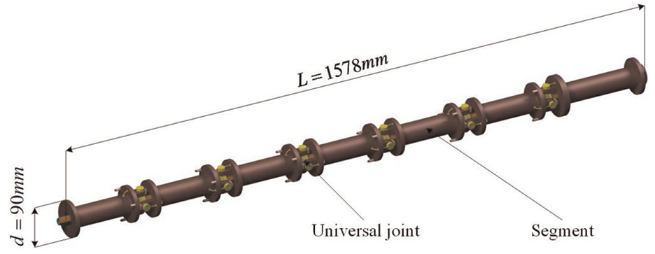
Snake-shaped body of the manipulator.
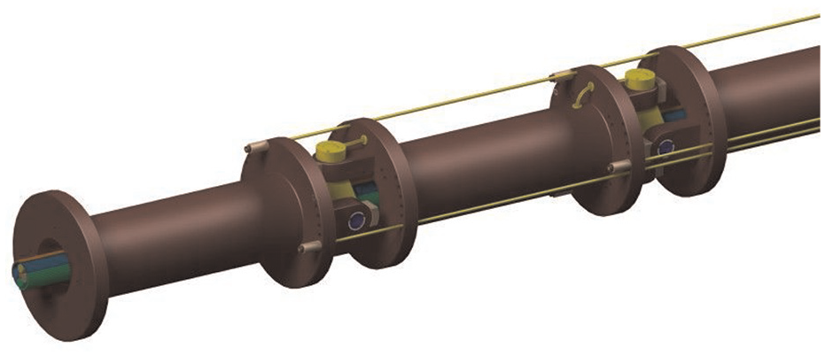
Single joint connecting rod is shown in Figure 7. It consists of a universal joint, two angle sensors, three cable fasteners, two cushion blocks, four sliding bearings, and several linear bearings. The angle sensors are used to build the feedback control system for the manipulator. The manipulator body is controlled by cables and each joint is driven by three cables. Three cable fasteners are used to fix the tip of the cable. In order to reduce the friction with the manipulator body, several linear bearings are set in the cable hole.

Single joint connecting rod.
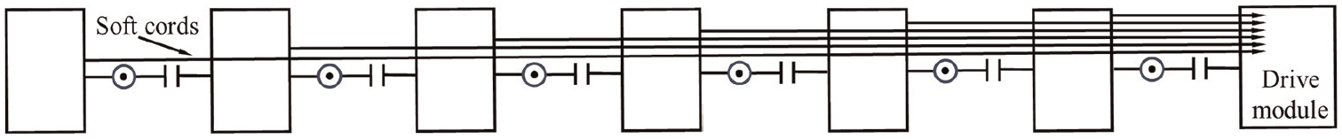
The full-drive mode is used to make the manipulator body get higher control accuracy and movement capacity during various jobs.24,25 As shown in Figure 8, each joint is controlled by three cables to achieve the rotation with two degrees of freedom. Three cables are evenly distributed for 120° apart. Each cable will pass through the controlled joint and the joints behind it and finally come out from the base joint. Therefore, there will be 18 cables passing through the base joint, and the numbers of cables passing through the subsequent joints are 15, 12, 9, 6, and 3 in sequence.
Joint control method.
As shown in Figure 9, the distribution diameter of the cables in the HRMGS changes as they travel from the Drive module to the Manipulator body, and this change can lead to problems such as increased friction. In order to solve this problem, we particularly designed the lubrication module to guide the flexible cable and reduce the friction. The lubrication module is made of nylon material with guide function. The friction between the flexible cable and the lubrication module avoids the damage between the flexible cable and the HRMGS body in the working process of HRMGS. At the same time, the friction generated is much less than that between the flexible cable and metal. Considering that the lubrication module will be worn after working a period of time because of fatigue, the module is designed as a rapidly replaceable structure and used as consumables.

Guide lubrication module.
In order to reduce the size of the manipulator body, we integrate the cable-driven system at the tail of the manipulator body. 26 As shown in Figure 10, the drive module consists of 18 sub-drive units and each sub-drive unit can control one cable. The cable is fixed with the slider and is driven by a screw-driven system. And the motor is connected with the screw through a coupling. Tension sensors are fixed to the end of the cable, which are used to monitor the tension of each cable.

Drive module.
The feedback system includes an angle feedback module and a tension feedback module. As shown in Figure 11, the angle feedback module is located at the universal joint. There are two angle sensors at each universal joint. The tension feedback module is located at the connection between the drive module and the flexible cable. The angle sensor is used to record the real-time joint angle, which can guide the manipulator to move in time. The tension sensor is used to record the real-time tension of each cable to ensure the cable is in a safe cable tension range.

Sensor feedback system.
In order to realize the gluing operation, it is necessary to design a gluing tool at the end of the manipulator body. At the same time, it is necessary to design a visual system for visual positioning and real-time detection of the quality of the glue seam after gluing. As shown in Figure 12, the base of the visual operation device is a hollow U-shaped shell and the middle part is the glue application tool. There is a camera at each end and a line laser is fixed on the top of the base. The line laser and one of the cameras constitute an active light visual positioning device for end visual positioning. The other camera is used for real-time detection of glue seam quality. The three-dimensional spatial dimensions of the visual operation device are 150, 120, and 95 mm, individually. The total weight is 0.5 kg, which meets the load requirements.

Terminal visual operation device.
Figure 13 is a cross-sectional view of the glue pushing device. The push motor is fixed to the base. Its shaft is connected to a 14-mm-diameter threaded shaft and fixed with a small bolt. The threaded shaft is coupled to the push tube with internal threads through threads. So, the rotation of the motor will drive the push tube to move forward and backward. This can make full use of the space of the visual operation device. The effective glue pushing length is 60 mm.

Cross-sectional view of terminal visual operation device.
Different from the existing six-axis robot, the hyper-redundant snake-shaped manipulator gluing system (HRMGS) we designed needs to control a large number of motors at the same time. In order to solve this problem, we make the computer and the industrial controller cooperate with each other to control the entire drive system. As shown in Figure 14, the computer is mainly used to complete tasks that require more computing power, such as image information processing and path planning. Computer calculates the angle sequence of the HRM during its motion and transmits it to industrial controller using the OP CUA transmission protocol. Industrial controller is equipped with a Codesys real-time multi-axis control system. It is mainly responsible for coordinating the synchronous rotation of the motors and the execution of the underlying control algorithm. 27 In order to avoid excessive load on the CAN bus, 16 motor control boards are evenly distributed on two CAN buses. The industrial controller communicates with the motor control boards through these two CAN buses to achieve multi-axis synchronous control of the motors.

Control framework of HRMGS.
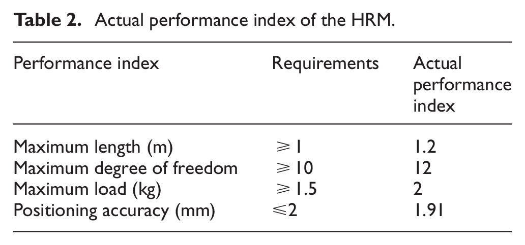
Finally, the design of the HRM is completed, and the prototype of the HRM is developed according to the design. As shown in Figure 15, the robot meets the design indicators, and the actual indicators are shown in the Table 2. The verification process will be reflected in the experiment in section ‘Experiment’.

The prototype of the HRMGS.
Actual performance index of the HRM.
Kinematics model of the robot system
In order to establish the kinematics model of the HRM, we need to establish the joint coordinate system and establish the conversion relationship between the joint coordinate systems. Figure 16 is the front view and top view of the connection between link i − 1 and link i. Three coordinate systems are established at each joint. The coordinate system


Joint coordinate system.
According to Figure 17, the transformation matrix


Coordinate system of HRM.
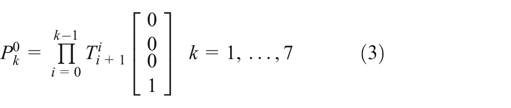
So far, we have established the conversion relationship between the base coordinate system and the coordinate systems of each joint of HRM. Thus, the coordinates of each hinge point
Motion planning algorithm
During the HRM gluing process, there are two types of movement modes. The first is that the robot arm crosses a space full of obstacles to reach the target working position. The second is that the tip of the robot arm moves along the working path while the other parts of the robot arm automatically avoid obstacles in the space.
Regardless of the movement mode, the robotic arm will be constrained by the environment, operation, and body posture. Environmental constraints refer to the need for HRM to avoid obstacles during its movement. Generally, the artificial potential field method can be used to model obstacles to guide the robot to avoid obstacles. Operation constraint means that the gluing head needs to maintain the operating posture when operating. This constraint can be satisfied by adjusting the angle of the end joint.
The shape constraints of HRM mainly come from two aspects. The first part is the limitation of the joint structure, and the second part is the limitation of the rope drive and control method. Firstly, the joint angles of HRM need to be within a certain range due to the limitations of the joint structure, that is,
This paper proposes a multi-step method for HRM motion planning under multi-constraint conditions. The first step is to use the end joint freedom of the robot arm to make the end posture meet the requirements according to the operation constraints and set the position of the last hinge point as the new target position. The second step is to use the artificial potential field method to obtain the target path curve according to the environmental constraints and obtain discrete path points through sparse sampling. The third step is to fit the target path curve through discrete points and obtain the robot arm joint angle according to the shape constraint solution.
There has been a lot of relevant research work on the first two steps. This paper mainly discusses the third step and improves the algorithm. William and Mayhew 22 proposed a possible solution where William et al. models the target path curve as polyline segments and then fits the manipulator link to the target path curve. However, modeling the target path curve as a broken line segment will reduce the obstacle avoidance capacity of the manipulator, which is not advisable in complex and narrow working spaces. Therefore, we use higher-order curves to model motion paths. 28 At the same time, it also brings the problem of complex calculation, that is, when performing curve fitting, it is necessary to solve an equation of more than three degrees.
Figure 13 shows the curve fitting process. The blue line is the target path curve. Assuming that there are three connecting rods

Schematic diagram of the curve fitting process.
We can model the above problem as an optimization problem of equation (4) where

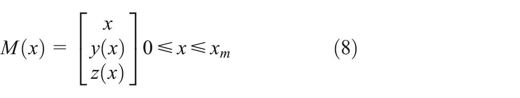
We use the parametric equation (5) to model the target road curve.

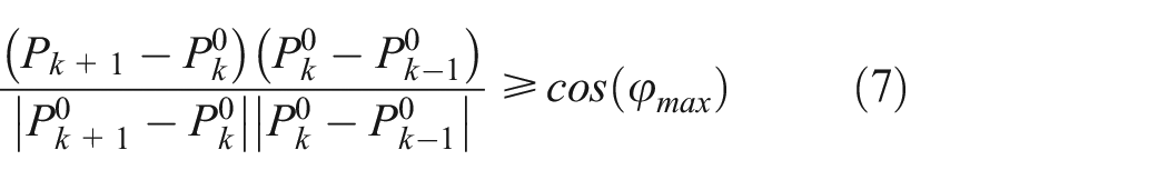
There are also some constraints to help model this problem. Equation (6) is the link length constraint, and equation (7) is the angle constraint of each joint.

Numerical computation of curve fitting
In the process of solving the above algorithm, since the curve equation is of high order, it is necessary to solve the high-order equation, which requires a lot of computing time. 29 We therefore propose a numerical calculation method as shown in Figure 19. Our algorithm is divided into several steps: monotonicity test, curve fitting calculation, iterative calculation, and accuracy test.

Curve fitting algorithm.
In most cases, HRM will only move in one direction. And we first assume that the HRM moves in the x direction. The curve equation can be rewritten as:
For curves that are not monotonic in the x direction, we need to divide the curve into multiple parts according to monotonicity. And the curve equation can be rewritten as:

Where
In the step of curve fitting calculation, we first calculate the push distance and determine the number of joints that need to be moved. Then we can obtain the curve segment where the joint link is located through the push distance. Since the curve is monotonic in the
Curve fitting algorithm.

Computational speed optimization based on posture recording
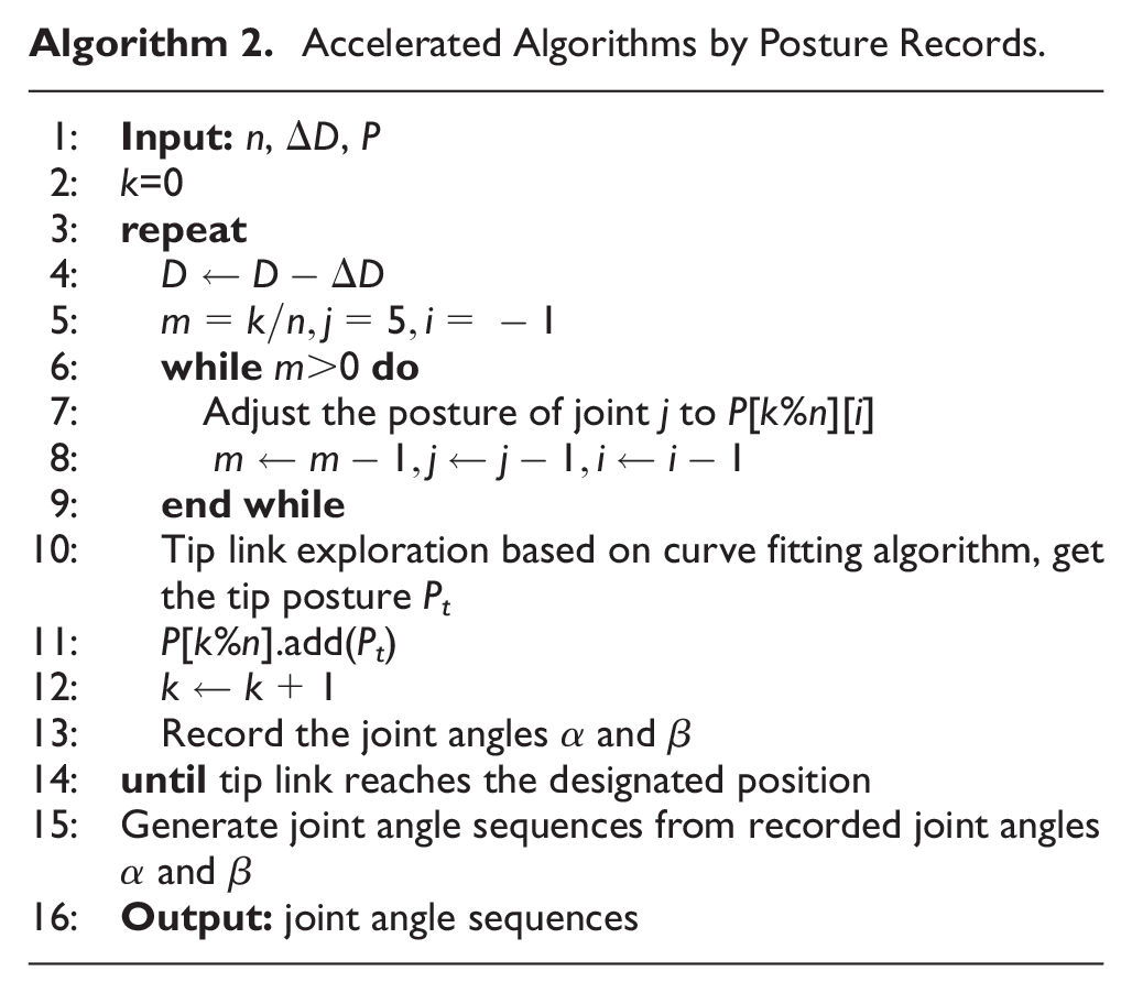
When HRM performs a traversing motion, we find that the posture of each link has two characteristics: consistency and time delay. Consistency means that each joint has the same posture when passing through the same path position. Time delay means that the time for each joint to pass through a certain path position is delayed. Specifically, when the push distance is exactly the link length, the posture of the connecting link
Therefore, if the historical link postures are recorded, we only need to calculate the tip link posture and the rest postures of other links can be obtained from the historical postures. In the actual motion control process, if the link length is directly used as the motion step, the span between the steps is too large, and the motion between two steps is uncontrollable. So, we can evenly divide it into
Accelerated Algorithms by Posture Records.
Inference speed optimization by neural networks
When HRM is gluing, multiple algorithms such as image detection and glue seam positioning are running synchronously. The number of joints of the hyper-redundant manipulator is large and the constraint relationship is complex. The kinematic solution process should be as fast as possible. Considering the powerful fitting capacity of neural networks, we try to use neural networks to fit the kinematic solution process, so as to further improve the kinematic solution speed in actual operation.
We use MLP neural network to solve this problem.
30
We conducted research on single-path and multi-path respectively, and achieved excellent results in the case of single-path. Figure 20 is the structure of our neural network. The input of the neural network contains two parts. The first part is the push distance D, and the second part is the path information

Neural network structure.
We established the corresponding dataset using numerical solution and divided it into training set, validation set, and test set. A series of experiments were carried out on the fitting effect of the neural network. We used 160 pieces of data as the training set, 20 pieces of data as the verification set, and 20 pieces of data as the test set, and the three sets did not have any cross data. After training for 9.651 h and 30,000 epochs, the verification loss dropped to 0.004561, and the test loss dropped to 0.0043. Since we are using the MSE loss function, the angle error is 0.06°. Therefore, it can be seen that the neural network fitting algorithm can achieve high precision. Besides, the size of the neural network model is 0.7 MB and the inference speed is 0.67 ms.
Experiment
Multi constraint trajectory planning experiment
The multi-obstacle environment is designed, and the obstacle avoidance crossing is taken as the constraint. Using the trajectory planning strategy of the super redundant robot under the multiple constraints studied in this paper, the position and attitude of HRM are fitted to complete the trajectory planning. The results are shown in Figure 21, and the green points are the actual fitting points. It can be found that the fitting points successfully avoid obstacles and realize the crossing, which proves the effectiveness of the research strategy in this paper.

Obstacle avoidance trajectory planning.
Comparison of path curve modeling methods
In order to visually show the difference between modeling the target path using polylines and using high-order curves to model the target path, we reproduced the method 22 and designed simulation experiments for comparison.
In the simulation experiment, we set four target waypoints. In our method, the target path will be modeled as a curve and expressed in the form of parametric equations. Since there are four goal paths, we use a cubic function to represent each dimension to ensure that the path curve can pass through these four path points. In the method, 22 the target path is modeled directly using polyline segments, so three polyline segments are obtained.
Figures 22 and 23 are joint angle sequences used to control HRM obtained by these two methods respectively. From Figure 16, we can find that when the target path is modeled as a high-order curve, the angle sequence changes more smoothly, which is more friendly for HRM control.

Timing diagram of
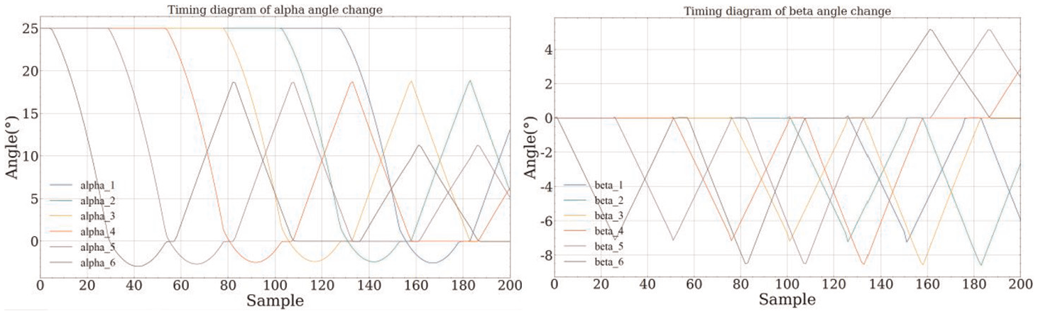
Timing diagram of
Neural network fitting experiment
In order to verify that the neural network we designed has the capacity to fit functions rather than memorize certain data, we designed two sets of experiments.
Firstly, we used different data volumes as training sets and carried out six sets of experiments. 31 The amount of data used in each experiment is shown in Table 3. In these experiments, the training set, validation set, and test set have no cross data. During the training process, the loss of each experiment on the training set and validation set is shown in Figure 24. The final results are shown in Table 4. It can be seen from Figure 24 and Table 4 that as the amount of data decreases, the convergence speed of the fitting training of the neural network gradually slows down, but it will eventually converge gradually. Furthermore, as the size of the training set decreases, the time it takes to train for the same epoch also decreases. Therefore, we conducted further experiments and found that in the case of the same training time, the model using less training data can also have good performance.
Different experimental settings.


(a) (b)Partial magnification of loss on validation set after 8000 and (b) (b)Partial magnification of loss on validation set after 8000.
Results of different experiments.

Secondly, we expanded the size of our dataset to 2k by extending the path length and increasing the number of path-point samples. Then, by changing the proportion of the training set data and the number of training iterations, the results show that the model still performs well when the amount of data in the dataset increases and the number of training iterations decreases.
Comparison of different algorithms
In this paper, we propose several motion planning algorithms for HRM. Table 5 compares the performance and characteristics of different algorithms, where algorithm 1 is the analytical method, algorithm 2 is the numerical method we proposed, algorithm 3 is the optimized numerical method through posture recording, and algorithm 4 is the curve fitting method using neural network.
Consumed time of different experiments.

As can be seen from the Table 5, the analytical method is very time-consuming. Through the numerical calculation method we designed, the calculation time is greatly reduced. Under the same situation, the single-step time consumption reached 27.29 ms. After optimization using the posture recording method, the calculation time is further reduced to one-third of the original. In addition, we found that using a neural network for fitting calculations can further accelerate calculations under a single simple path. Under the same circumstances, the calculation speed can be increased to five times with a certain accuracy.
Length and degree of freedom experiment
For the length experiment, the HRM is straightened directly and measured with a meter ruler. The measurement result is 1.2 m, which meets the index requirements. The operation is shown in Figure 25. For the mobility experiment of the HRM, according to the field observation, there are six Hooke hinges in HRM in total, and there are two degrees of freedom for each Hooke hinge, so there are 12 degrees of freedom altogether, meeting the index requirements.

Length experiment.
Load experiment
For the loading capacity test of the HRM, we let the HRM in a horizontal straight-line extension state, and two 1 kg-weights are loaded at the end of the HRM. After 1 s, move the dial indicator to the end of the HRM. If the variation of the needle runout is less than 0.1 mm, it is considered that the HRM can carry 2 kg. The specific operation is shown in Figure 26. In the actual measurement, the dial indicator needle changes by 0.02 mm after loading for 1 s, indicating that the designed HRM meets the design requirements.

Load performance experiment.
Dynamic response experiment
The dynamic response time and accuracy of the HRM are tested by setting the target angle, and the system operations in accordance with the control program. The time and angle deviation are tested during the process of reaching the target angle.
First, the dynamic response experiment of the sixth joint was carried out to test the deflection time and accuracy, as shown in Figure 27. The corresponding joint angles of the sixth joint are

Dynamic response experiment of the sixth joint.
The experimental results are shown in Figure 28 which indicates that,

Dynamic response experiment result of the sixth joint.
In order to further verify the dynamic response capacity of the HRM, the multi-joint dynamic response experiment of deflection from all joint angles was carried out, as shown in Figure 29.
Dynamic response experiment of deflection from all joints.
The design experimental data are shown in Table 6. Figure 30 shows the statistical results of the experiment. Each joint angle is deflected twice, from 0° to 5°, and then from 5° to 0°.
Experimental data for all joints (°).


Dynamic response experiment of all joints.
By analyzing the experimental results and curves, the following conclusions are obtained: the single joint motion robot can complete 5° deflection in 0.5 s, and the error is within ±0.1°. The multi-joint motion robot can complete 5° deflection within 1 s, and the error is within ±0.12°. The deflection curve of single joint is nonlinear, which is mainly caused by many factors such as motor speed, elastic deformation of flexible cable, friction, and so on; The rotation curve of each joint of multi-joint deflection is approximately linear.
The main reason is that the adjustment time becomes longer, and each time is basically in equilibrium. The influence of external nonlinear factors has been basically eliminated, so it presents a linear relationship. In addition, the experiment shows that if the speed of angle adjustment continues to be accelerated, the robot cannot maintain accuracy and stable movement, and each joint vibrates, which does not meet the requirements of practical industrial applications. To sum up, the multi-joint dynamic response accuracy of snake robot is ±0.12°, and the maximum response speed is 5°/s.
Positioning accuracy experiment
The robot’s positioning accuracy

The repetitive positioning accuracy
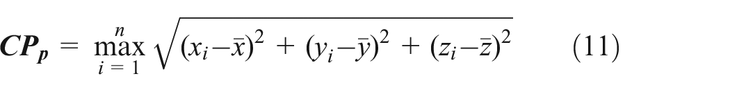
Referring to the positioning error measurement method of industrial robots, four typical target points
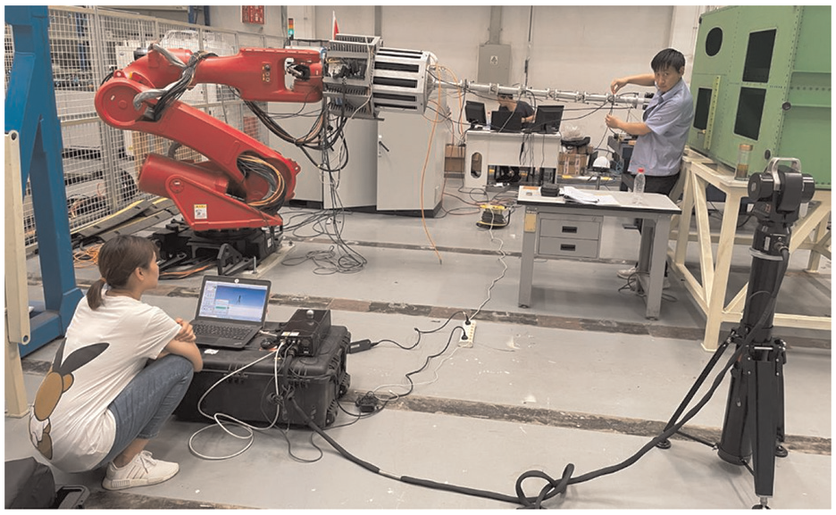
Positioning accuracy measurement.
Measurement results of the positioning accuracy measurement.

From the above results, it can be seen that the positioning accuracy of the HRM is 1.91 mm, and the repeated positioning accuracy is 0.76 mm. In the actual operation, several experiments were carried out, and different fitting methods and motion strategies were adopted, and finally the method with the highest actual positioning accuracy was selected. This precision can meet the precision requirements of gluing operation in actual production.
Physical experiment
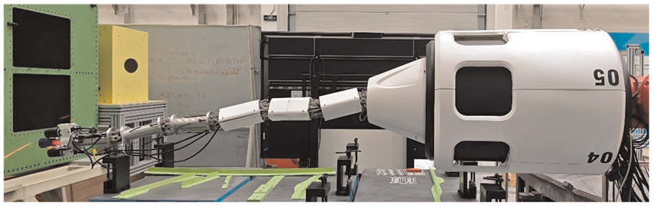
In order to verify the feasibility of our HRM, we made a physical prototype and carried out multiple motion tests and gluing tests. Our HRMGS is performing a gluing task in a narrow space as shown in Figure 32. And Figure 33 is the real-time picture in the gluing process.

HRMGS is performing a gluing task.

Real-time picture in gluing process.
Conclusions
This paper designs a hyper-redundant gluing system (HRMGS) that can be used to carry out automated gluing operations in narrow spaces. The dynamic response capacity and joint steady-state accuracy of the designed HRM are verified by dynamic experiments. The dynamic response capacity of a single joint can reach 12.5°/s, the steady-state accuracy is less than ±0.08°, the comprehensive dynamic response capacity of multiple joints can reach 5°/s, and the steady-state accuracy is less than ±0.12°. The positioning accuracy of the HRM is verified by the positioning accuracy experiment, and the final comprehensive positioning accuracy of the HRM can reach 1.91 mm. A multi-stage solution method is proposed for the motion planning problem of HRM under multiple constraints. A numerical solution method is proposed, which can fit the high-order path curve to obtain the motion posture of the robot arm. In this way, the robotic arm can maintain a smooth posture during movement. In the traversal motion, we used a posture recording method to improve the speed of the numerical solution method, which can increase the solution speed by four times. Besides, we try to use a neural network to fit the kinematics equations. In the situation of one single path, the neural network has a strong fitting capacity and can achieve high accuracy and inference speed. The current effect of multi-path fitting is relatively lacking, and related work can be continued in the future. Finally, we verified the feasibility of the structure and the effectiveness of the algorithm through various motion experiments on physical prototypes.
Footnotes
Handling Editor: Sharmili Pandian
Funding
The author(s) disclosed receipt of the following financial support for the research, authorship, and/or publication of this article: This work was supported in part by the National Natural Science Foundation under Grants 62273344 and 62206275.
Declaration of conflicting interests
The author(s) declared no potential conflicts of interest with respect to the research, authorship, and/or publication of this article.