
Abstract
This study employs Hamilton’s principle and a bi-dimensional finite element method (Bi-d FEM) to investigate the dispersion characteristics and resonant modes of linear and circular wedge acoustic waveguides. The ANSYS three-dimensional FEM is commonly used to analyze waveguides and calculate the resonance frequency of vibration modes. However, the accuracy of this approach is constrained by how finely the elements are divided, limiting its applicability to the analysis of lower-order resonant modes. Therefore, to extend the analysis to high-frequency and high-order resonance modes, the Bi-d FEM is used. Based on the separation of variables method, this approach discretizes the time-harmonic propagation factor and the cross-sectional vibration of guided waves into two-dimensional finite elements. The number of divided elements is reduced, resulting in considerably improved calculation accuracy. The Bi-d FEM results indicate that the antisymmetric wave mode of the linear wedge acoustic waveguide decreases with vertex angle and that the wave velocity is lower than the Rayleigh wave velocity, which is consistent with the results obtained using Lagasse’s empirical formula. In both linear and circular wedge acoustic waveguides, the energy of the guided wave is concentrated at the wedge tip; therefore, it exhibit the characteristic behavior of an antisymmetric flexural wave.
Keywords
Introduction
Research on wedge acoustic waveguides began in the 1970s. Since Lagasse’s discovery of guided wave behavior at the wedge tip in 1972, 1 scholars have paid increasing attention to guided wave propagation in wedge bodies. Several studies have revealed that the majority of the energy in antisymmetric flexural (ASF) waves propagating along the tip of the wedge is localized at the apex itself. Moreover, the propagation velocity of the waves is slower than the Rayleigh wave velocity of the material, and they exhibit no dispersion characteristics. To describe the physical behavior of the propagation of guided waves in wedge structures, several studies have established mathematical models that accord well with experiment. However, owing to the complex geometric boundary value problems associated with the propagation behavior of wedge guided waves, a precise analytical solution remains elusive. Therefore, only approximate solutions are obtainable through numerical analysis.
In 1972, Lagasse 1 and Maradudin et al. 2 employed numerical calculations to verify the waveguide effect of a wedge with a vertex angle within a specific angular range. They demonstrated that the antisymmetric guided wave propagating along the tip of the wedge has most of its energy confined to a region within approximately one wavelength from the tip of the wedge. This guided wave does not exhibit dispersion when the tip of the wedge is not truncated.
In 1973, Lagasse et al.
3
proposed a simple empirical formula to summarize the numerical results. For integer multiples of the vertex angle less than or equal to 90° (i.e.
In 1973, Lagasse 4 employed the finite element method with the second-order triangular interpolation function to divide acoustic waveguides of different cross-sectional shapes. This approach investigated the wave propagation behavior of infinitely long linear wedge waveguides and analyzed the dispersion phenomena of guided waves in different geometric cross-sections. This study combined the variational principle and finite element analysis to develop a powerful method for studying wave propagation in acoustic waveguides.
In 1976, Mckenna et al. 5 approximated an infinitely long wedge with a small vertex angle as a thin plate. Using plate and shell theory, they derived an expression for the relationship between the phase velocity and the wavenumber of the guided wave for both truncated and untruncated wedges. In 1996, Hladky-Hennion 6 conducted numerical analyses, including the FEM to investigate the propagation behavior of linear and circular wedge guided waves. The effects of curvature radius, vertex angle, and vertex angle truncation on the phase velocity of wedge guided waves were studied.
In 1994, Krylov 7 adopted geometrical acoustics theory to calculate the propagation velocity of guided waves in a wedge in water. Their results indicated that the wave velocity decreases under the influence of water coupling and that this velocity reduction has a non-linear relationship with the vertex angle of the wedge. Moreover, it was predicted that a propeller exhibiting a motion pattern similar to that of a sting ray could be developed using this low-velocity wedge guided wave. In 1999, Krylov 8 derived a simpler and faster analytical solution on the basis of geometric acoustics theory to describe the wave propagation behavior of conical wedges and conical wedge-like guided waves, demonstrating good agreement with the finite element analysis results of Hladky-Hennion. 6 In 2007, Krylov et al.9,10 experimentally validated the concept of wave-like aquatic propulsion for autonomous and crewed vessels; this concept was proposed a decade earlier. The first working prototype of a small catamaran using wave-like propulsion through an attached rubber keel was built and tested at Loughborough University.
In 1992 and 1993, Jia et al.11,12 applied laser ultrasonic technology to measure the propagation characteristics of wedge guided waves. Employing Nd: YAG pulse laser as the excitation source and an optical heterodyne interferometer for signal reception, they analyzed measured waveform signals to verify the empirical formula proposed by Lagasse. 3 They found that the number of anti-symmetric guided wave modes on the wedge decreased with the vertex angle. In 2016 and 2017, Jia et al.13,14 investigated the influence of truncation on the dispersion of wedge guided waves propagating along circular wedges using the laser ultrasound technique. A comparison of the dispersion curves revealed that the truncation of the vertex angle led to a dispersion effect in the guided wave, which became more pronounced at larger truncations.
In 1996, de Billy 15 used a contact transducer on each of the two sections of a linear wedge, an emitter, and a receiver to measure the velocity of guided waves. The results demonstrated the importance of minimizing the contact area between the emitter and sensor on the wedge and aligning the polarization direction of the emitter with the direction of the ASF guided wave vibration to obtain accurate measurements.
In 1998, Yang and Liaw 16 combined three-dimensional finite element analysis and laser ultrasonic experimental techniques to analyze and measure linear and disk-type wedges. Using a two-dimensional fast Fourier transform (2D-FFT), they mapped line scan wave propagation signal from the time domain to the frequency and wavenumber domains to obtain the phase velocity dispersion curve of the guided wave. This study demonstrated that the propagation behavior of disk-type wedge guided waves is influenced by curvature, resulting in dispersion. Moreover, the phase velocity dispersion decreases with frequency.
In 2003, Ibanescu et al. 17 analyzed the electromagnetic mode structure of an OmniGuide fiber: a hollow dielectric waveguide in which light is confined by a large index-contrast omnidirectional dielectric mirror. In 2006, Yang and Tsen 18 investigated the dispersion behavior of ASF modes propagating along the tip of a bilinear wedge using laser ultrasonic measurements and finite element numerical simulations.
In 2011, Mayer et al. 19 concluded that surface and interface acoustic waves are two-dimensional guided waves because their displacement field exhibit plane-wave-like behavior in spatial coordinates parallel to the guiding plane and decay exponentially along the axis normal to that plane. In the same year, Yu et al. 20 developed a modal separation model to enhance the performance of wedge-wave ultrasonic motors using the Bi-d FEM. In 2015, Yu 21 investigated the propagation of flexural waves along the outer edge of a circular wedge, considering phase velocities and corresponding mode displacements. Furthermore, in 2021, Yu 22 investigated the dispersive properties and resonant modes of ridge waves that travel circumferentially around piezoelectric circular ridge waveguides.
In 2013, Sokolova et al. 23 identified conditions under which acoustic waves guided at the apex of an ideal infinite elastic wedge exhibit weak dispersion. These conditions include (i) the coating of one or both surfaces of the infinite wedge, (ii) the truncation of the wedge apex or the use of a different material for the tip, and (iii) slight changes to material constants in an extended spatial region near the wedge tip.
In 2014, Dundu 24 studied the behavior of circular hollow members with flattened edges in compression. Variables in the experiments included the diameter, thickness, and length of the sections, and the number of bolts in the connection. In 2019, Serey et al. 25 introduced a general methodology for mode-selective generation in finite-cross-section waveguides using multiple transducers.
In 2021, Wang et al. 26 explored to explore the effect of the micro-structure interaction, the distribution of physical properties, and the structure size on the thermo-mechanical response of a typical functionally graded hollow cylindrical structure whose inner boundary is subjected to a sudden temperature rise. They obtained and validated layered-formed solutions.
In 2022, Spada et al. 27 presented a three-dimensional global–local formulation for predicting guided wave scattering patterns induced by discontinuities (e.g. defects). In 2023, Niu et al. 28 explored techniques to minimize the number of incident/scattered directions required for accurate simulation of the scattering matrix of an arbitrary defect. In 2024, Wei et al. 29 investigated the deformation of square plates with circular holes subjected to blast loads through experiment and simulation, and conducted explosion experiments and 2D to 3D mapping simulations.
This study proceeded in two stages. First, it used ANSYS for the modal analysis of a three-dimensional circular wedge model, simulated the wave propagation behavior of the circular wedge, established the dispersion curves, and investigated the convergence of finite elements. Second, it used the Bi-d FEM to calculate the dispersion curves and modes of linear and circular wedge acoustic waveguides with varying wedge angles and examined the influence of boundary conditions and curvature on the propagation of wedge guided waves.
Basic theory
Relationship between stress, strain, and displacement
For a linear wedge acoustic waveguide, in terms of the Cartesian coordinate system shown in Figure 1(a), the displacement vector


Linear and circular wedge acoustic waveguides: (a) linear wedge and (b) circular wedge.
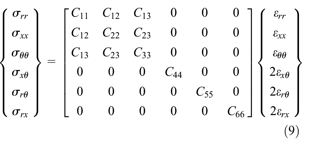
If the acoustic waveguide is considered as an orthotropic material, the relationship between stress and strain can be obtained using the generalized Hooke’s law as follows:

The relationship between strain and displacement is

For a circular wedge acoustic waveguide, in terms of the polar coordinate system shown in Figure 1(b), the displacement vector


Similarly, if the acoustic waveguide is considered an orthotropic material, the relationship between stress and strain is expressed as follows:
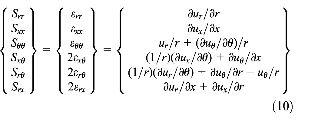
The relationship between strain and displacement is:
Hamilton’s principle
If zero surface traction is assumed for an infinitely long linear wedge acoustic waveguide, the waveguide’s strain energy


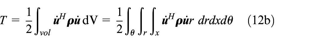
Following the same approach, considering the case where the surface traction of a circular acoustic waveguide is zero, its strain energy

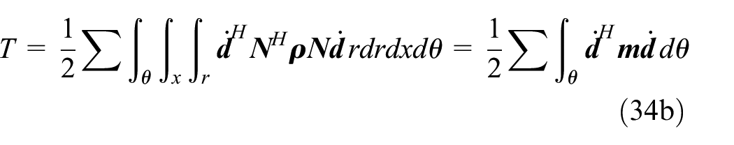
where
If
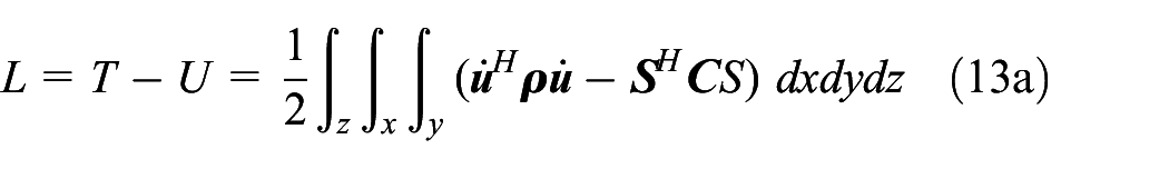

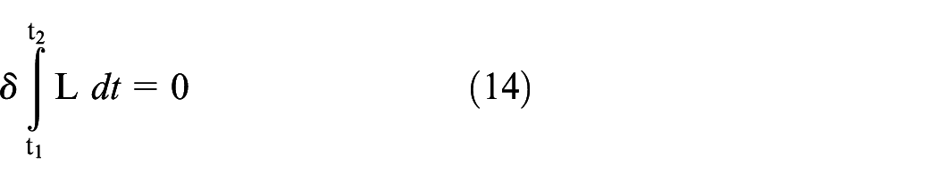
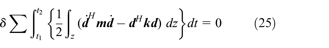
Applying Hamilton’s principle, the first variation of the Lagrangian time integral is set to zero:
Subsequently, the equations of motion for linear and circular acoustic waveguides can be derived.
Bi-dimensional finite element analysis
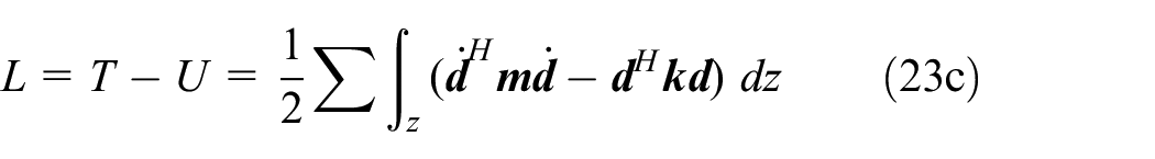
In equation (13a), the separation of variables method can be used to extract the Lagrangian of a linear acoustic waveguide from the integral over z. Similarly, in equation (13b), the Lagrangian of a circular acoustic waveguide can be extracted from the integral along the circumferential
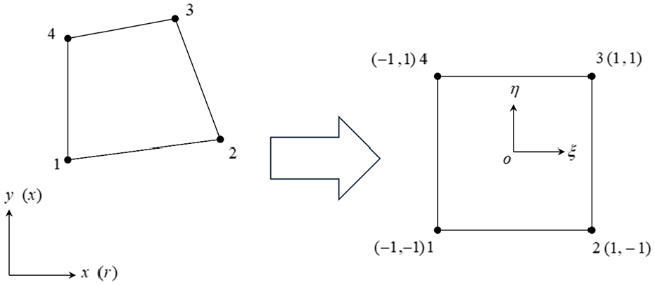
The Bi-d FEM is then used to discretize the cross-sections of the linear and circular acoustic waveguides into small elements (Figure 2). The displacement of any point within an element is expressed as the product of the element node displacement and the interpolation function. The element used in this study is a two-dimensional four-node isoparametric element (Q4).

Mesh map of linear and circular wedge acoustic waveguide: (a) linear wedge and (b) circular wedge.
A linear acoustic waveguide is considered in which the wave propagates along the positive z-direction, with the section perpendicular to the z-axis maintaining the resonant mode.
Therefore, referring to the coordinate system shown in Figure 1(a), the displacement vector

where
The displacement components of each element inside the acoustic waveguide are expressed as node displacements and interpolation functions.


where
Equation (16) can be expressed as follows (in matrix form):


where


Considering that the guided wave of a circular acoustic waveguide propagates along the circumferential direction, it maintains a resonance pattern in the cross-section perpendicular to the circumferential direction. Therefore, referring to the coordinate system of Figure 1(b), the displacement vector is assumed to be

where
The displacement components of each element inside the acoustic waveguide are expressed as node displacements and interpolation functions.


where
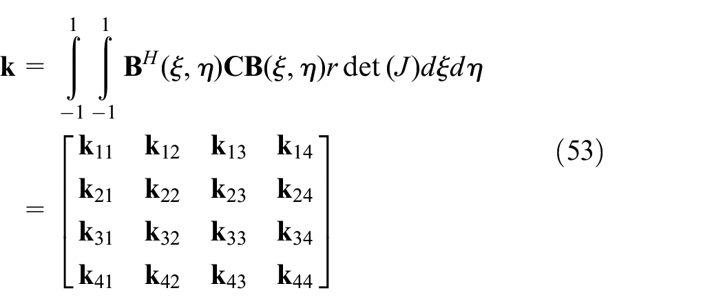
Equation (20) can be expressed in the following matrix form:

where


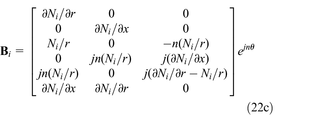
Substituting equation (20) into equation (10) for the polar coordinate system and expressing the strain vector in a matrix form result in

where

Dispersion equations
Dispersion equation for a linear acoustic waveguide
By substituting the expressions of the displacement


where

Here,
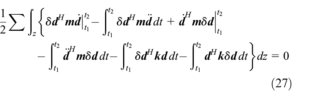
By performing variational operations on equation (25), we obtain

Then, using integration by parts to expand equation (26) yields
Considering that constraints

Therefore, the equation of motion of the linear acoustic waveguide can be expressed as follows:


where
Combining the discrete element matrices into a global matrix, the equation of motion of the system can be obtained as follows:

If the node displacement has a time harmonic factor

Equation (32) is an eigenvalue problem, and non-zero solution exists if and only if the determinant of the global matrix is zero.

Dispersion equation for a circular acoustic waveguide
By substituting the expressions for the displacement


where

Moreover,
Referring to equations (25)–(30), the equation of motion for the circular acoustic waveguide without external force is expressed as follows:

If the node displacement has a time harmonic factor

Equation (37) is an eigenvalue problem, and a non-zero solution exists if and only if the determinant of the global matrix is zero.

Transformation of element matrices
The interpolation function of equation (17d) is expressed in natural coordinates, and equation (18c) includes the derivatives of the interpolation function with respect to the actual coordinates
Conversion maps for global and natural coordinates.
According to the chain rule for differentiating two-variable functions,31,32 the partial derivatives of the interpolation function
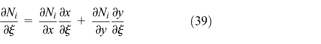
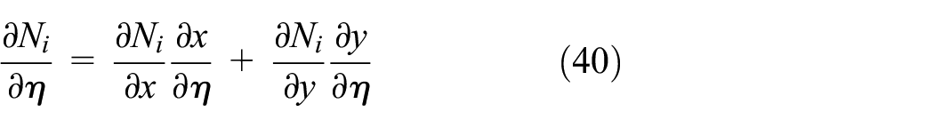
These equations can be written in matrix form as

where

Therefore, the partial derivatives of

where


The unit area

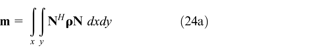
According to the aforementioned relationships, the element mass matrix (24a) of the linear acoustic waveguide can be expressed as

where

Here,

where
The matrices
Similarly, the element mass matrix (35a) of the circular acoustic waveguide can be expressed as

where

Here,

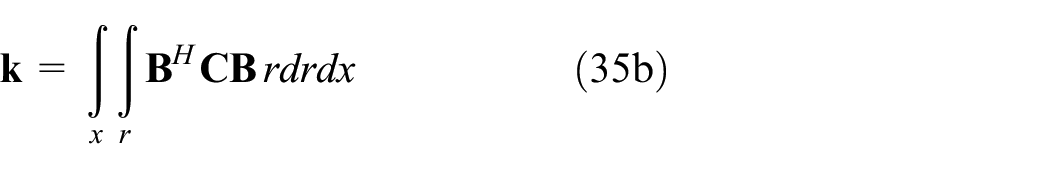
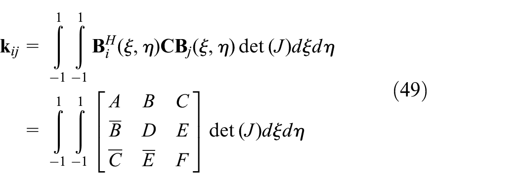
The element stiffness matrix (35b) of the circular acoustic waveguide is expressed as
where

Moreover, the matrices
Simulation results
Three-dimensional analysis of resonance modes
Finite element dynamic analysis
Modal analysis was performed using ANSYS to simulate the propagation behavior of guided waves in a circular wedge with a vertex wedge angle of 15°.33–35 Dynamic ANSYS finite element analysis proceeds in three stages: (i) pre-processing, (ii) solution, and (iii) post-processing.
In the pre-processing stage, a geometric model of the circular wedge was established with the following dimensions: vertex angle
Parameters of Ti. 36


3D ANSYS mesh map of a circular wedge.
In the solution stage, the modal analysis was performed, and the degrees of freedom of each node at the bottom of the circular wedge were assumed to be zero. Numerical calculations were then carried out.
In the post-processing stage, all resonant frequencies and corresponding resonant modes after modal analysis were determined. Antisymmetric wave modes and their associated resonant frequencies were subsequently selected for analysis. The phase velocity of the guided wave is calculated using the following formula:

where
Convergence analysis
The number of elements employed in finite element analysis influences the solution convergence. Divergence is likely when only a few elements are used, but the use of too many elements is computationally wasteful.
Thus, convergence analysis is conducted to determine the number of elements of mesh elements that strike the best trade-off between convergence and computational cost. In this study, the element mesh adheres to the following empirically derived guidelines for finite element wave propagation problems30,31:

where

where

According to the modal analysis results of this study, when the frequency is f = 90,575 Hz, the number of standing waves
On the basis of equation (58), the number of circumferential elements
Circular wedge element mesh.
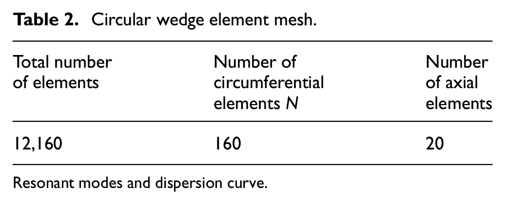
Resonant modes and dispersion curve.
After the 3D ANSYS method was used to analyze the resonant modes of the circular wedge acoustic waveguide, the natural frequencies of the circular wedge and the corresponding resonant modes did not wholly correspond to sequence ASF waves and indirectly combined with other vibration modes; thus, the appropriate frequency and mode must be selected to obtain the dispersion curve. During the selection process, natural frequencies may get duplicated and resonant modes may remain similar, differing only by a certain angle of rotation with respect to the z-axis.
Table 3 lists the frequencies at which antisymmetric modes occurred. Figure 5 shows the corresponding resonant mode diagram at each frequency, with the number of circumferential antisymmetric waves n on the circular wedge ranging from 1 to 10. Substituting the values of
Frequencies and wave velocities of a Ti circular wedge.


Resonant mode shapes obtained using 3D ANSYS: (a) n = 1, (b) n = 2, (c) n = 3, (d) n = 4, (e) n = 5, (f) n = 6, (g) n = 7, (h) n = 8, (i) n = 9, and (j) n = 10.
A comparison of these results with those obtained via Bi-d FEM analysis (Figure 6) revealed minor discrepancies in the dispersion curves found using the two approaches. When the wavenumber

Comparison between the 3D ANSYS and Bi-d FEM results for the first mode.
Bi-d FEM analysis results
The results of the 3D ANSYS analysis of the resonant modes indicated that the method faced limitations related to element discretization, restricting its effectiveness to low-frequency modes. In this study, the Bi-d FEM was employed to analyze guided wave propagation behavior. The separation of variables method was used to decouple the time-harmonic propagation factor from the cross-sectional vibrational modes. This enabled an analysis of the high frequency modes, providing insights into guided wave propagation and motion with respect to cross-sectional resonant modes.
Equations (32) and (37) represent the dispersion equations for linear and circular acoustic waveguides, respectively. Solving for eigenvalues and corresponding eigenvectors of these characteristic equations yields dispersion curves and resonant modes, elucidating wave propagation characteristics of linear and circular guided waves. Numerical solutions and simulation programs for the Bi-d FEM were implemented using FORTRAN.
The method used to solve the eigenvalue problems involves fixing the wavenumber
The resonant mode is calculated on the basis of the direction of the dispersion curve, thereby fixing the wavenumber
The following calculations are based on the specific cases of linear and circular acoustic waveguides with different cross-sectional shapes, in which Ti metal is used as the material. The Bi-d FEM was used to establish dispersion curves and resonant mode shapes, and the effects of boundary conditions and curvature on wedge guided wave propagation were investigated.
Dispersion curve and mode shapes of a linear wedge
This study considered a linear wedge with a vertex angle of 30° and a cross-sectional height H = 18.67 mm (Figure 2(a)). The cross-section was divided into 680 elements with 757 nodes, and the number of degrees of freedom of each node at the bottom was set to zero. The results of the analysis are shown in Figure 7. For each resonant mode, the solid lines represent dispersion curves, and dotted lines represent phase velocities obtained using Lagasse’s empirical formulas
Dispersion curves of a linear wedge with a vertex angle of
As shown in Figure 7, a linear wedge with a vertex angle of
Figure 7 indicates a rapid increase in phase velocities for each mode’s dispersion curve at low wavenumbers. This is affected by the constraints of the degrees of freedom of each node at the bottom. However, beyond a certain wavenumber, the dispersion curves become nearly horizontal, indicating minimal dispersion effects during guided wave propagation.
Figure 8 shows 3D mesh maps of linear wedges with wedge angles of 30° and 15°. Figures 9 to 11 illustrate resonant mode shapes of linear wedges with a vertex angle of 30° at various wavenumbers; the resonant mode corresponding to each dispersion curve changed substantially as the wavenumber increased. At low wavenumber

3D models of linear wedges: (a) 30° wedge and (b) 15° wedge.

First-mode shapes of a linear wedge with a vertex angle of

Second-mode shapes of a linear wedge with a vertex angle of

Third-mode shapes of a linear wedge with a vertex angle of
Figure 12 compares the dispersion curves of a linear wedge with a vertex angle of

Comparison of the dispersion curves of a linear wedge with a vertex angle of 30° under different bottom boundary conditions.
Subsequently, we considered a linear wedge acoustic waveguide with a vertex angle of
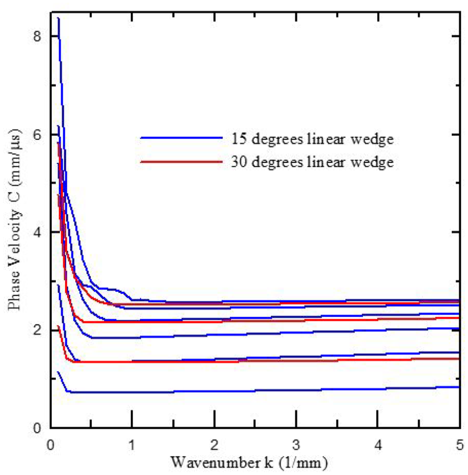
Comparison of the dispersion curves of linear wedges with wedge angles of 30° and 15°.
Figure 13 shows that in the dispersion curve of each mode at low wavenumbers, the phase velocity is affected by the constraints of the number of degrees of freedom of each node at the bottom boundary and increases rapidly. When the wavenumber was greater than a certain value, the dispersion curves of each mode almost flattened, indicating that the numerical analysis results are consistent with Lagasse’s conclusion 3 that no dispersion phenomenon exists in the guided waves of ideal linear wedges.
Dispersion curve and mode shapes of a circular wedge
The cross-sectional shape of the circular wedge acoustic waveguide analyzed in this study is shown in Figure 2(b), and its corresponding 3D mesh map analyzed using ANSYS is shown in Figure 4.
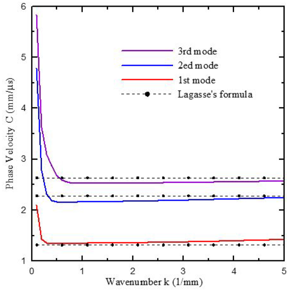
The wedge had a vertex angle of

Dispersion curve of a circular wedge with a vertex angle of 15°.
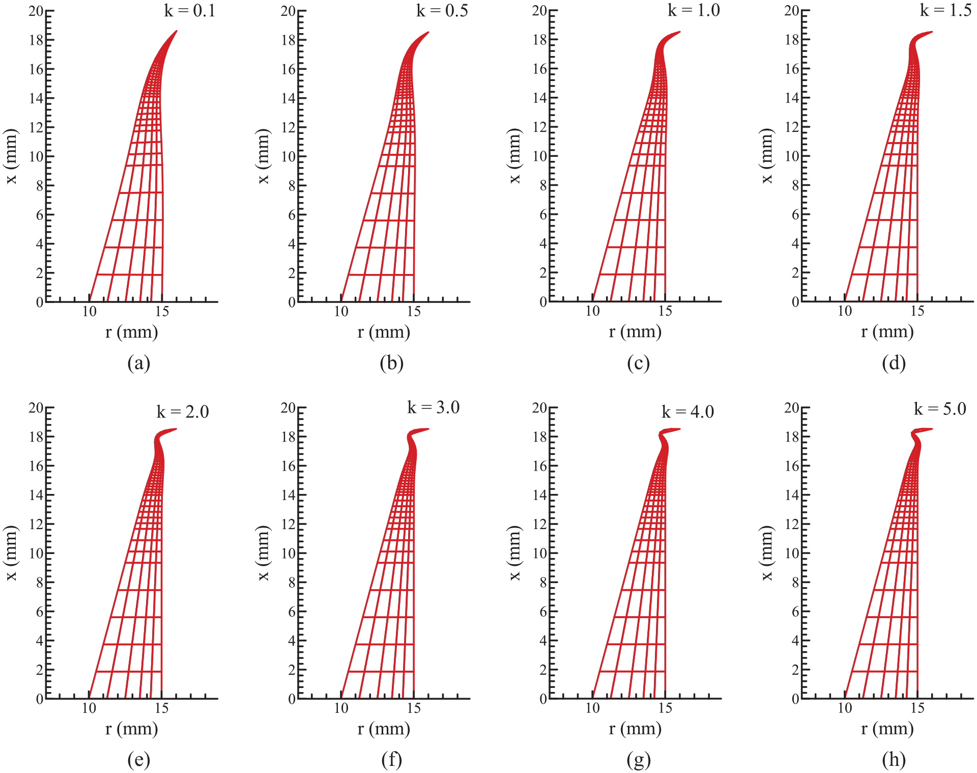
Figures 15 to 19 illustrate the resonant mode shapes at different wavenumbers. As

First-mode shapes of the 15° circular wedge: (a) k = 0.1, (b) k = 0.5, (c) k = 1.0, (d) k = 1.5, (e) k = 2.0, (f) k = 3.0, (g) k = 4.0, and (h) k = 5.0.

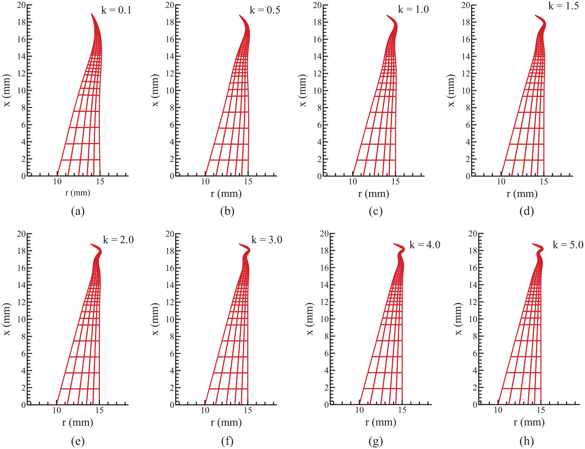
Second-mode shapes of the 15° circular wedge: (a) k = 0.1, (b) k = 0.5, (c) k = 1.0, (d) k = 1.5, (e) k = 2.0, (f) k = 3.0, (g) k = 4.0, and (h) k = 5.0.
Third-mode shapes of the 15° circular wedge: (a) k = 0.1, (b) k = 0.5, (c) k = 1.0, (d) k = 1.5, (e) k = 2.0, (f) k = 3.0, (g) k = 4.0, and (h) k = 5.0.
Fourth-mode shapes of the 15° circular wedge: (a) k = 0.1, (b) k = 0.5, (c) k = 1.0, (d) k = 1.5, (e) k = 2.0, (f) k = 3.0, (g) k = 4.0, and (h) k = 5.0.

Fifth-mode shapes of the 15° circular wedge: (a) k = 0.1, (b) k = 0.5, (c) k = 1.0, (d) k = 1.5, (e) k = 2.0, (f) k = 3.0, (g) k = 4.0, and (h) k = 5.0.
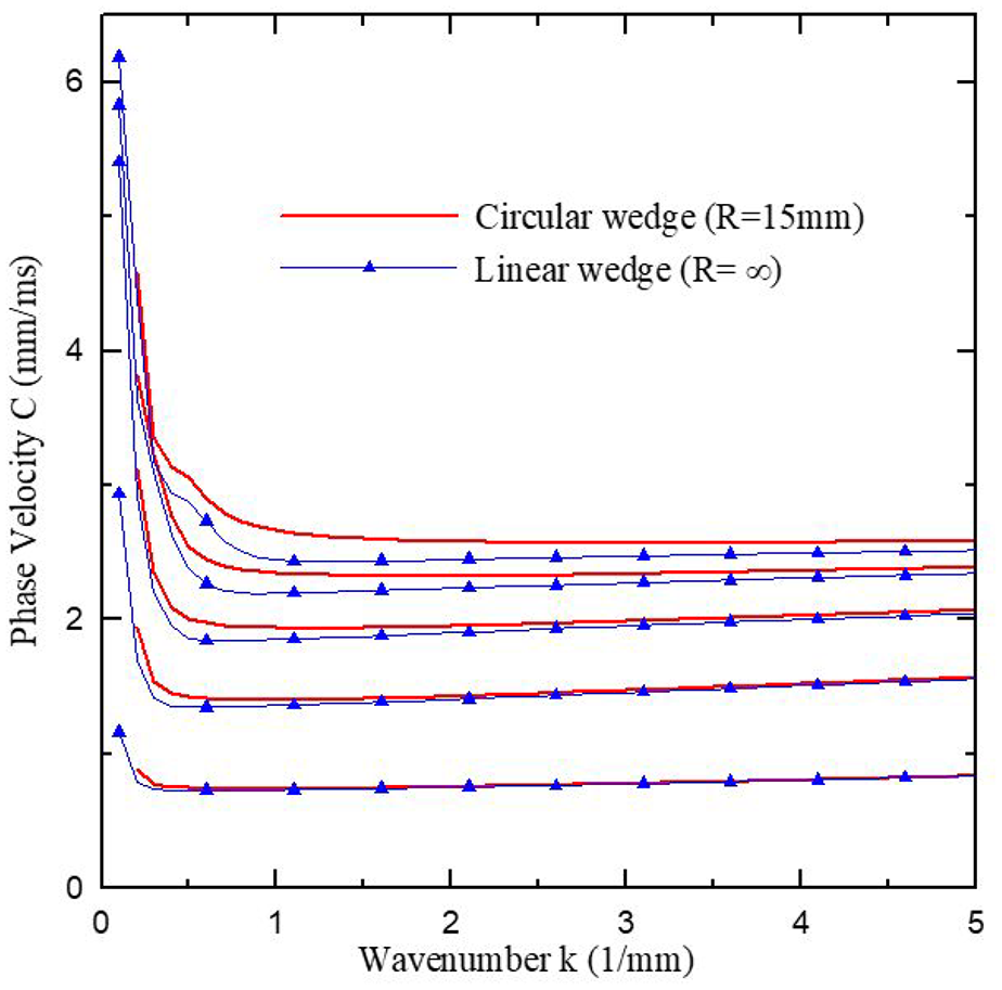
Figure 20 shows the comparison of the dispersion curves for circular (R = 15 mm) and linear (R = ∞) wedges acoustic waveguides, both with a vertex angle of
Comparison between the linear wedge (R = ∞) and circular wedge (R = 15 mm).
We conclude that for low-order modes, the influence of the curvature of the acoustic waveguide is minimal, resulting in similar phase velocity dispersion curves for linear and circular wedges. However, for higher-order modes, the influence of the curvature on the phase velocity becomes more pronounced.
Conclusion and discussion
3D ANSYS resonant mode analysis yields resonant frequencies and modes in ascending order; however, not all are antisymmetric. To obtain a dispersion curve, appropriate frequencies and modes must be selected. During the selection process, resonant modes may coincide with subtly distinct ones differing by a rotational angle. This arises owing to the irrational nature of a circle’s circumference and the integer discretization of elements, resulting in an error in the number of significant digits and thus causing differences in numerical calculations. The accuracy of ANSYS analysis of circular wedges with 3D finite elements is limited by the number of element divisions. Therefore, to precisely investigate the wave propagation behavior of antisymmetric guided waves in acoustic waveguides, this study uses the Bi-d FEM instead of resonance analysis with 3D finite elements.
Our Bi-d FEM calculation confirm that the number of antisymmetric wave modes in a linear wedge acoustic waveguide decreases as the vertex angle increases, with the wave velocity of each mode being less than the Rayleigh wave velocity. Assuming a phase velocity below the Rayleigh wave velocity (V
R
= 2.634 mm/µs), linear acoustic waveguide with vertex angle of
Owing to the boundary conditions at the bottom of the dispersion curves of the linear and circular wedge acoustic waveguides, the phase velocity increases considerably at low frequencies. This indicates that the boundary conditions only influence wedge acoustic waveguides in low-frequency bands.
When the wavenumber
The influence of a structural curvature on the guided wave phase velocity of a wedge becomes more pronounced for higher modes. The guided wave phase velocity in a circular wedge increases relative to its linear counterpart as the resonant mode order increases.
The obtained resonant mode shapes confirm that the wedge acoustic waveguide exhibits the largest displacement at its tip. This indicates that the energy of the wave is concentrated at the tip, and the guided wave is an ASF wave. The Bi-d FEM proves to be a powerful analysis method for the study of wave propagation in circular and linear acoustic waveguides.
This study methodology can be extended in future research to investigate linear and circular wedge acoustic waveguides with different cross-sectional geometries, wedge angles, truncations, and coatings. Such investigations can lead to the development of ultrasonic motors and related applications.
Footnotes
Acknowledgements
We express our sincere thanks to the National Science and Technology Council in Taiwan (NSTC 112-2221-E-239-002) and the National United University (114-NUUPRJ-13) for their generous support in funding this research.
Handling Editor: Sharmili Pandian
Funding
The author received no financial support for the research, authorship, and/or publication of this article.
Conflicting interests
The author declared no potential conflicts of interest with respect to the research, authorship, and/or publication of this article.