
Abstract
In robot-assisted dental implant surgery, properly arranging the robot system are important for performance. Following this, a multiobjective optimization approach for preoperative robot placement (MOPRP) is proposed. Firstly, after kinematics modeling, the 9-dimensional planning of both the joint’s angles and the base’s position is simplified into 3-dimensional planning of merely the base’s position, building the design variables. The simplification is based on a multiple inverse kinematics (IK) selection strategy, which contains a collision-free principle and score-based selection. Secondly, three multiobjective indices, including the error range index, dexterity index, and joint variation index, are derived to evaluate placement quality. Subsequently, a Pareto front is generated through the multiobjective genetic algorithm, offering a group of competitive solutions. Lastly, by selecting a favorable solution from the Pareto front and checking its 3D preview, the placement planning can be done. Both numerical tests and experimental validations are conducted, demonstrating that the result approximately ranks in the 80%–90%, 99%, and 80%–90% percentile respectively for the three indices. The results show that MOPRP can provide enhanced dexterity, better accuracy, and less joint variation, with a pretty system layout, verifying its effectiveness and feasibility as a useful planning tool.
Keywords
Introduction
Tooth loss, especially among the elderly, significantly impacts the daily life.1,2 Dental implantation can restore most of the functions and is the most effective therapy.3,4 In recent years, robot-assisted dental implant surgery has become a new solution, which has great potential to provide better surgery and relieve the shortage of dentists. 5 With these advantages, robot-assisted dental implant surgery is likely to become mainstream in the future.
The field of dental implant robots has attracted many researchers.6,7 Sun et al. developed a system integrating a drilling robot, a measuring arm, and an imaging system.8,9 Cheng et al. proposed a system using a UR5 robotic arm and studied stereo vision. 10 Tao et al. introduced a collaborative robot system combining a parallel mechanism and force-based guiding, 11 with similar work by Yan et al. 12 While these works have developed robotic systems, an integrated system alone is not sufficient. The system arrangement (e.g. the position of robot and the angles of robot joints before surgery) remains an important issue. Good arrangement can enhance manipulability and accuracy,13,14 while poor arrangement can degrade performance and even cause singular workspace issues. 15
For medical robots, some work has been conducted to plan the system. Hayashibe et al. developed simulation software for preoperative setup, which helps doctors preview the motion. 16 Yu et al. proposed an automatic planning method through reinforcement learning for their celiac surgery robot, building a simplified model of the abdomen, and obtaining the best entrance posture. 17 A similar mathematical model of the surgical area is made use of in another work, where three characteristic parameters for the incision are obtained and used to decide the incisions. 18 Liang et al. developed a preoperative optimization method by evaluating the motion performance including workspace, collision safety, and dexterity for another celiac surgical robot, 19 and then optimized the preoperative setup using particle swarm optimization. Preda et al. developed a planning software to determine the depth and angle of surgical instruments during laparoscopic surgery. 20 Badani et al. optimized the placement of the camera port to reduce the risk of collision. 21 Trejos et al. assessed the performance of an endoscopic robot by involving the global conditioning index and then solved the port location. 22 Yang et al. proposed the planning method with the evaluation indices of visibility, operability, and hand-eye coordination, adopting a multiobjective particle swarm optimization method to determine the suitable area for cholecystectomy. 23 In addition, Qin et al. pay attention to the preoperative planning of the optical tracking system (OTS) by generating the osteotomy paths and finding the optimal poses of the OTS. 24
In summary, for the preoperative setup of robots, the entrance to intervene in the body and the operation performance are usually being focused on. Other issues such as collision, dexterity, and workspace are common items to be considered for evaluation. Optimization methods including PSO or genetic algorithm (GA), along with their multiobjective versions, are often adopted to obtain an acceptable setup. While previous studies have made an array of progress, there is still some room for further research. Current literature seldom addresses the layout planning for dental/oral surgical robot systems, and clinical doctors still need a planning tool for assistance. Also, reducing motion errors and additional disturbance is rarely considered, which are the specified features of oral/dental surgery. The main contributions/novelty of our MOPRP can be summarized as follows:
(1) While current literature for robotic dental/oral surgery rarely plans the robot system, our MOPRP arranges the system to enhance performance, serving as a useful tool for practitioners.
(2) For the high accuracy required in dental implantation, MOPRP analyzes the motion error and optimizes joint configuration, reducing the error transmission from joints to the actuator, which is an issue seldom discussed currently. 25
(3) MOPRP reduces the disturbance to patients during feeding motion, as patients closely watch the robot whose excessive disturbance can cause stress and impact the surgery, especially since the patient’s head is not fixed. This is a characteristic of oral surgery and contrasts with laparoscopic surgery where patients are under general anesthesia.
(4) The simplification of design variables in MOPRP is useful for various planning problems, and multiobjective optimization provides a solution set for complex tasks, 26 making MOPRP not only fit the specific needs of dental/oral surgery but also its components have potential for similar applications.
The rest of the paper is organized as follows: Section “Task and main line” introduces the task and an overview of MOPRP. Section “Robot kinematics and IK selection” models the kinematics and provides the IK selection strategy, which is the foundation optimization. Section “Multiobjective indices establishment” analyzes three multiobjective indices for performance evaluation. Numerical tests, experiments, and discussions are carried out in Section “Result and discussion.” Conclusion is provided in Section “Conclusion.”
Task and main line
Planning task
To conduct MOPRP, we use our dental implant robot system,27–30 involving a robotic arm, an implanting actuator,
27
and a drilling actuator.
30
As shown in Figure 1(a), the arm carries the actuators to perform the surgical operation. As shown in Figure 1(b), MOPRP determines the placement of the robotic arm, including the base’s position and the joint angles, including the position from the oral cavity to the robot base

System overview and planning task: (a) the dental implant robotic system and (b) the preoperative placement task for the robotic arm.
Main line of MOPRP
The main line consists of three stages: establishing design variables, building indices, and multiobjective solving, as shown in Figure 2. In stage 1, the 9-dimension planning including

Main line and data flow of MOPRP: (a) the main line consists of three stages and (b) detailed data flow of MOPRP.
Robot kinematics and IK selection
Kinematics modeling
Forward kinematics
The product of exponentials (POE) method is used for forward kinematics, where frames {Base}, {End}, and {Oral} are shown in Figure 1(b). Required parameters are listed in Table 1, where
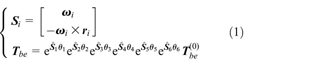
where
The POE parameters for kinematics modeling.

Jacobian matrix
The Jacobian matrix is the core for the error mapping index and dexterity index. The space Jacobian

where

where
Target position and posture
To perform implantation, {End} should coincide with {Oral}, the Y-axis and X-axis of {End} should respectively coincide with the Z-axis and the negative Y-axis of {Oral}. Since Joint 1 is a 360° joint, it is natural to fix the orientation of {Base}: the X-axis and Z-axis of {Base} respectively parallel with the X-axis and Y-axis of {Oral}, displayed in Figure 1(b). With these settings, the joint angles for a given


where
Multiple IK results selection
The IK result in equation (6) usually contains multiple candidates such as eight groups and the objective function cannot be uniquely determined. Thus, a representative IK result need be selected for
Removing invalid results
Firstly, undesired IK results can be filtered using collision-free principle which has two conditions shown in equation (7).

where condition 1 prevents the arm from contacting the cabinet shown in Figure 3(a). In condition 2,
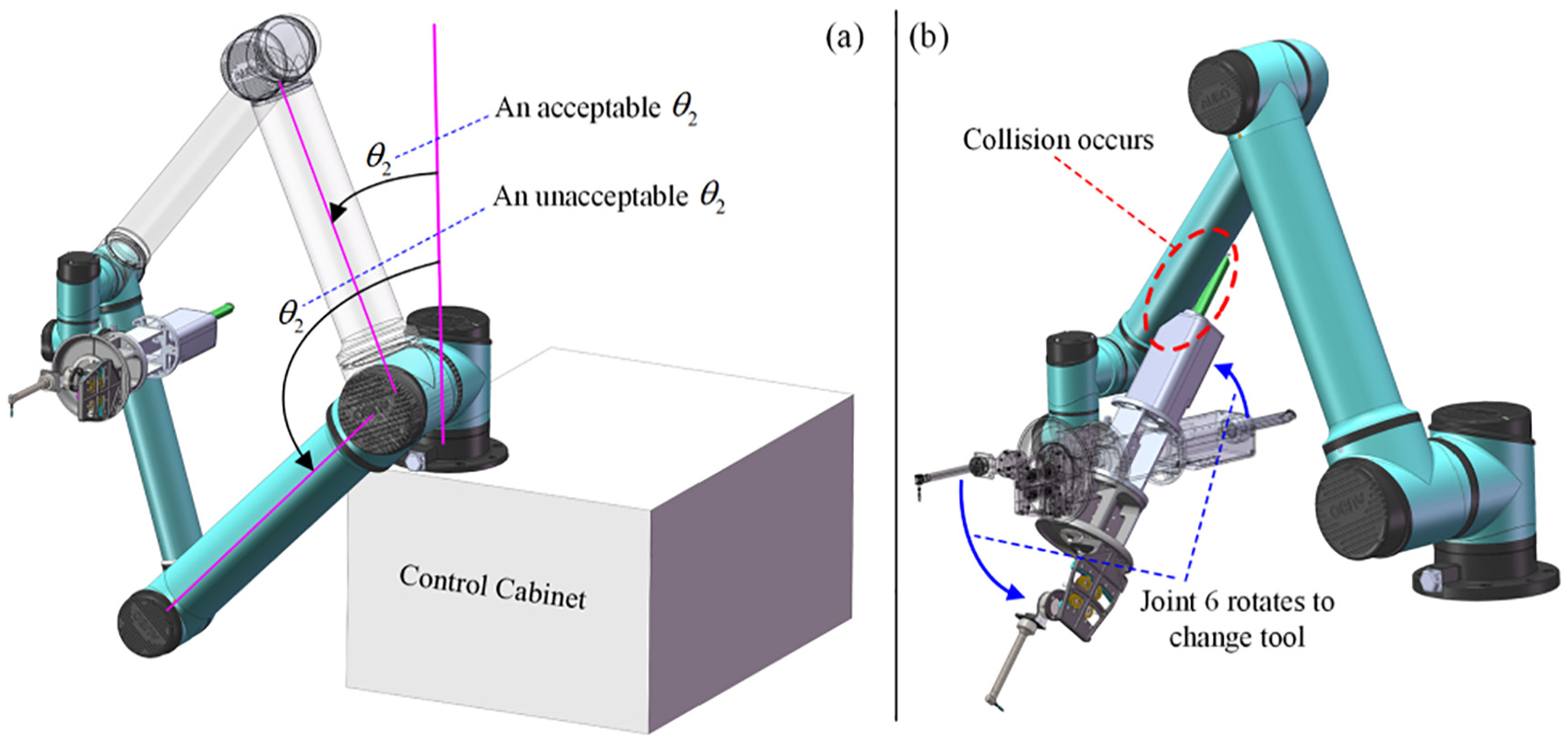
Collision-free principle for removing invalid IK results: (a) condition for joint 2 and (b) collision between actuators and arm should be avoided.
Score-based selection
After removing invalid IK results, a score-based strategy will select the representative from the remaining candidates. Now, assuming three indices (Section “Multiobjective indices establishment”) and

Flowchart of score-based selection, which selects one representative from multiple IK results.
In the IK selection strategy, solving the inverse kinematics is done by the robot’s SDK function, returning all the groups of IK candidates, which are the input of the score-based selection strategy. That is to say, IK selection is the post-processing of IK solving. Moreover, the IK selection plays the role of simplifying constrained optimization, for which other methods like the penalty function method or Lagrange multiplier method may also be available. However other traditional methods will incorporate the multidimensional and complex kinematics constraint function without reducing the problem dimension or even importing additional dimensions, making the optimization solving too complex. In addition, when two IK candidates simultaneously score the highest, we directly choose one randomly, record its index number for subsequent processing, and the unselected candidate will be ignored. This may lose some useful information (discussed later), but it still provides a sufficiently competitive IK candidate, and fully meets the requirement of dimension reduction.
Multiobjective indices establishment
Dexterity index
The dexterity index

where
Error range index
The error range index calculates the range of the actuator’s tracking error under the assumption that the joint angles have a random error of

where
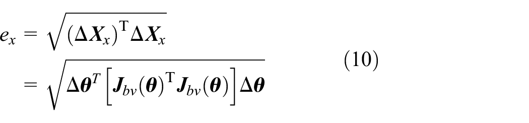
Assuming the joint’s error range to be

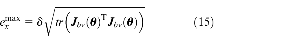
Since getting the error range is finding the maximum value of a positive definite quadratic form

where

Because

Since the eigenvalues of a quadratic form remain unchanged within orthogonal transformation, the value

where

By substituting equation (17) into equation (16), it can be seen that

Then, extract the rotational part of equation (2), the calculation of

where

From equation (20), it can be drawn that the error range of posture is a constant. Therefore, to evaluate the error range, the position error range

Joints variation index
The joints variation index
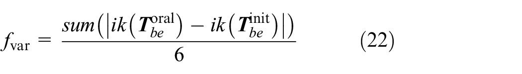
where

Joints variation index: (a) the actuator’s position before and after motion and (b) flowchart for calculating the index.
Moreover, the above calculation only considers the start and end points. For the feeding, the master-slave control based on a virtual fixture is employed, 29 which follows the manual driving and the virtual fixture that corrects the manual commands by hindering undesired movements. Although master-slave driving has randomness, a good placement can reduce the joint’s swings significantly. As patients in oral surgery are usually awake and closely focused on the moving robot, smaller joint variation means less stress to the patients, and less disturbance to the doctor, reducing the risk of misoperation.
Result and discussion
Numerical tests
In this section, MOPRP is programmed through MATLAB, and the multiobjective genetic algorithm (GA) is adopted to obtain a solution set called the Pareto front, where all the results are non-dominated. In GA, the population size is 500, the iteration number is 500, and the joint error is set to be

Two examples for numerical tests: (a) the first example where a patient is lying and (b) the second example where a patient is sitting.
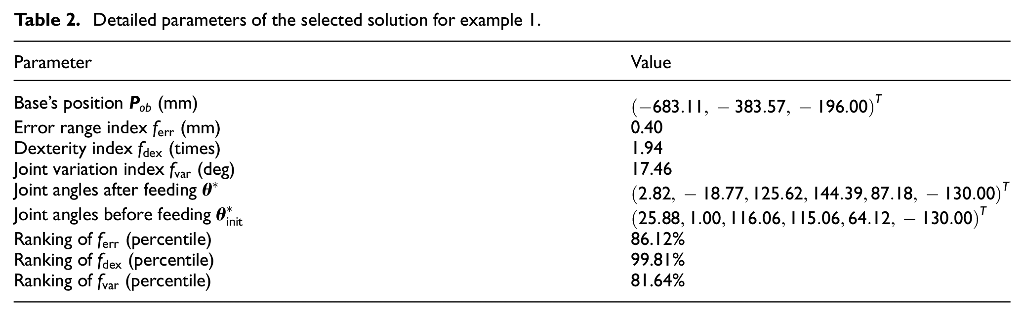
For example 1, the Pareto front is displayed in the design and objective space (Figure 7(a) and (b)). We select

Result returned by MOPRP for example 1: (a) Pareto front in design space, (b) Pareto front in objective space, (c) system layout of selected solution after feeding the actuator, and (d) system layout of selected solution before feeding the actuator.
Detailed parameters of the selected solution for example 1.
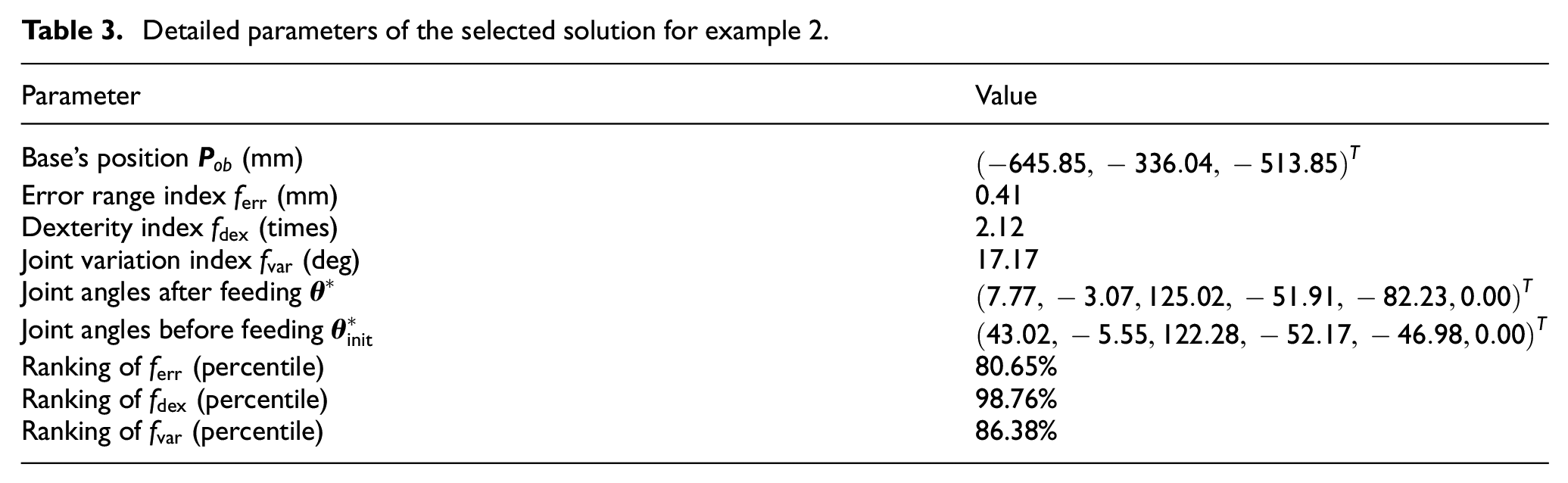
For example 2, the Pareto front is shown in Figure 8(a) and (b). The layout after feeding motion is shown in Figure 8(c), and the layout before feeding is shown in Figure 8(d). The ranking of the selected solution are:

Result returned by MOPRP for example 2: (a) Pareto front in design space, (b) Pareto front in objective space, (c) system layout of selected solution after feeding the actuator, and (d) system layout of selected solution before feeding the actuator.
Detailed parameters of the selected solution for example 2.
Experimental validation
The experiment validation uses the example from Section “Kinematics modeling,” including tests on error mapping, joint variation, and dexterity performance. The experimental setup, shown in Figure 9(a), includes a robot arm, a master handle, an oral model, and an actuator. During the experiments, we tested the selected solution (Table 3) and 20 random solutions, providing a systematic comparison.

Working site for conducting experimental validation.
Result of error mapping test
To evaluate error mapping, the robot arm is commanded to run a circular path with a 25 mm radius and 10 mm/s velocity, as shown in Figure 10(a). The motion error is evaluated by the deformation from the desired to the executed path, as shown in Figure 10(b) to (e). All the 21 solutions are tested, acquiring the distribution of path error, as depicted in Figure 11. Although samples 5, 8, 10, and 11 perform better, the selected solution ranks well compared to all random solutions.

Evaluate error mapping by executing a circle path: (a) working site, (b) desired and executed path for the selected solution, (c) desired and executed path for the 5th random solution, (d) counterparts for the 10th random solution, and (e) counterparts for the 15th random solution.

Average value and distribution of the selected solution and 20 random sampled solutions in path error tests, the label “win” represents the selected solution.
Result of joint variation test
For this test, we use the master-slave control based on virtual fixture. When moving the master handle, the actuator is pushed into the oral cavity. For each of the 21 solutions, 10 sub-groups of feeding are performed to obtain statistical results. The working site before and after feeding the actuator is shown in Figure 12(a) and (b). The average joint variation curve for all 10 sub-groups of the selected solution is shown in Figure 12(c), and the actuator’s path for all 10 sub-groups is shown in Figure 12(d). Note that the joint’s variation is the overall traveled distance, rather than simply subtracting the starting angle from the ending angle, as written in equation (23):

where

Evaluate joint variation under master-slave control: (a) working site before feeding the actuator, (b) working site after feeding the actuator, (c) increase process of average joint swing angel of all the 10 sub-groups for the selected solution, and (d) executed paths of all the 10 sub-groups for the selected solution.
The average joint variation and its distribution for all 21 solutions are shown in Figure 13. Except for samples 9, 12, and 15, no samples rank better than the selected solution. For error mapping (Figure 11) where samples 5, 8, 10, and 11 had smaller motion errors, we see that these samples perform much worse in joint variation tests. Conversely, samples with smaller joint swings rank much poorer in path error tests. This indicates that while a random sample might perform slightly better in one test, it rarely excels in another, highlighting MOPRP’s advantage in providing a well-balanced solution.

Average value and distribution of the selected solution and 20 random sampled solutions in joint variation tests, the label “win” represents the selected solution.
Furthermore, while the specific master-slave strategy can influence the result (joint swing angle) for a single test, it will not impact the statistical results of multiple tests under the same master-slave control strategy. There are various methods for master-slave control, such as absolute mapping, incremental mapping, Euler angle mapping, rotation vector mapping, and some virtual fixture methods. Under different master-slave strategies, the patterns of the robot motion process differ, thus affecting the result of a single experiment. However, because multiple tests under the same master-slave strategy can statistically demonstrate the result distribution, the whole tendency of repeated results will remain the same, therefore the specified master-slave method does not influence the entire joint swing angle test.
Result of dexterity test
To check dexterity, the General Isotropy Index (GII) is introduced, which is a more comprehensive evaluation. We randomly sample 100 points within a 50 × 50 × 50 mm, 50 × 50 × 50 deg space of the oral cavity, and calculate their 6 × 6 body Jacobian (equation (3)). Subsequently, we take the smallest and the largest singular value among all 100 Jacobian matrices and calculated their ratio to be the GII index, as shown in equation (24). The larger this index, the better the dexterity. The performance of all these 21 solutions in GII is plotted in Figure 14, and the selected solution definitely has the best ranking.

where W is the point set distributed in the oral space,

Bar plots of GII values for all 21 solutions, the label “win” represents the selected solution.
Furthermore, there are two reasons why GII is not used as the optimizing objective. First, the linear and angular units are not unified, making it difficult to intuitively check the dexterity and in particular during the selection stage. Separating linear and angular motion in the dexterity index is more intuitive for assessing the motion isotropy. Second, sampling many points within the workspace, multiplied by the population of GA, will result in a huge computational burden and slow down the solving. Additionally, dexterity test is based on numerical calculations because it is fully characterized by the Jacobian matrix rather than direct measurement from robot motion.
Discussion
About indices and results
In MOPRP, three indices are introduced, including the dexterity index, error mapping index, and joint variation index. The reasons for using these indices are as follows. The dexterity index is responsible for checking the manipulability and avoiding too large/small joint-to-actuator motion transmission, thus it can improve the maneuverability and prevent malformed manipulating or uncontrollable situations from happening. Also, we separate the linear and angular parts of the Jacobian matrix and use the larger condition number as the index value. This processing can make users check the quality of the results more intuitively. The error mapping index is responsible for curbing the path tracking error during the implantation since the accuracy requirement is high. Under this requirement, a robot configuration that can transmit less error from the joint space to the actuator will be preferable. On the contrary, the joint error caused by servo control, trajectory interpolation, and mechanical gap will be magnified, lowering the quality of hole drilling and implant inserting. The joint variation index helps produce smooth feeding, reducing unnecessary impact or disturbance on patients and doctors. In other words, under this index, a good configuration can produce less swing of the arm, reducing possible stress of the patient, and making the doctor more focused on the operation. Thus, this easily neglected index can be of great practical importance. To sum up, the aspects of manipulability, accuracy, and operating experience are paid attention to, forming a comprehensive multiobjective evaluation.
As the indices
Following this, conflicts between the indices make it difficult to achieve ideal performance simultaneously. For instance, top rankings for
About method details
In the method design, while the IK selection strategy plays an important role for reducing the problem dimensions, there are three potential limitations. The first case is more than one IK solutions achieve the highest score. In this case, we randomly select one, and other IK solutions will not be considered, losing some useful IK information. The second case involves a non 6-DOF arm. The IK solution for redundant arms is infinite, meaning the introducing of additional constraints or numerical iteration. For an underactuated arm, due to the loss of DOF, the actuator cannot freely satisfy a given oral-to-base position with a fixed posture, and thus additional base-to-oral posture adjustment should be solved. The third case is the potential unfairness of the score assignment principle. Because it is hard to precisely determine the weight of each index, so we treat the three indices equally. But, the equal treatment may cause some potential unfairness in that the actual importance differs between them.
Despite these potential limitations, most collaborative arms usually have 6 DOFs. Moreover, since half of IK solutions are removed by collision conditions, the possibility of tied first-place scores is also low. In addition, although some possible imbalance between indices may cause unfairness, the winner IK candidate is reliable enough and of high efficiency. Thus, these potential limitations in this DOF simplification process is slight and entirely acceptable.
About practical implementation
Numerical tests and experiments show two layout scenes: aligned status after feeding the actuator (Figures 7(c) and 8(c)) and initial status before feeding the actuator (Figures 7(d) and 8(d)). While optimization focuses on the post-feeding status, the initial status is more important for practice as it can be directly arranged by the doctor.
The layout implementation involves an adjustable patient bed/chair, an integrated cart, and a stereo-vision system. First, the patient bed height should be adjusted via a remote controller to meet the selected solution in the Z direction, making more Pareto front solutions accessible. Second, for oral surgery robots, the robot arm, actuator, and the control system are typically integrated into a wheeled cart (see Figure 7), which can be easily moved and locked, making it matches the selected solution in the X and Y direction. Third, a stereo vision system should be involved, which can detect a vision marker worn on the patient, determining the oral cavity’s position. After hand-eye calibration, the relative position between the vision system and the robot base can be known. The doctor can then adjust the bed/chair and move the cart until the measured position matches the selected solution. Thus, for a fully deployed surgical robot system, the selected solution can be easily implemented.
Conclusion
In this study, we propose a preoperative placement planning approach called MOPRP, aimed at improving motion quality by planning the system layout before robot-assisted dental implant surgery. The approach is conducted by establishing design variables, deriving multiobjective indices, and optimization solving. During the establishment of design variables, we designed a multiple inverse kinematics (IK) selection method that simplifies the original 9-dimensional optimization problem into a 3-dimensional optimization by removing invalid IK results and employing a score-based strategy. Additionally, we derived three indices to evaluate the actuator’s dexterity, error range, and joint variation performance when certain joint angles are given and found that only the position error range can be optimized, and the posture error range remains unchanged. By running the multiobjective genetic algorithm, we obtained a series of competitive solutions, the Pareto front, from which a solution is selected and validated by evaluating its ranking and checking its system layout. Based on the selected solution, we conducted a series of experiments on the real robot, confirming the effectiveness and feasibility of the proposed MOPRP method.
In the future, we plan to develop 3D software that packs the MOPRP core solver, result selection, percentile ranking, and 3D previewing, which can facilitate on-site use and guide the layout arrangement for practitioners. Also, we will further test MOPRP by comparing our MOPRP with other similar works in terms of accuracy and efficiency, offering more detailed performance data.