
Abstract
Due to the errors of manufacturing and installation of the rotor system, there is a certain deviation between the centroid and the geometric center of the rotor, known as eccentricity, which causes the bending and torsional vibrations during operation, resulting in bending-torsion coupling vibrations. This paper aims at gaining insight into bending-torsion coupled vibrations of a rotor system with imbalance and oil-film bearings. Considering the nonlinear force for sliding bearings and the gyroscopic effect of the rotor system, the dynamic model of the rotor-bearing system with imbalance is established, the influence of the rotational speed and eccentricity of the rotor on the dynamics is investigated. In order to guide the assembly of the rotor with multiple bladed disks, the influence of the initial eccentric phase difference on the bending-torsion coupling vibrations of the unbalanced rotor system is also explored. It is innovative to study the transfer mechanism of the initial eccentric phase difference of the double disks to the nonlinear vibrations. The result indicates that near the first order torsional critical speed of the rotor system, the contribution of torsional vibration to the total vibration exceeds that of the bending vibration; when the rotor is operated at the first order bending or torsion critical speed, the vibrational amplitude of the rotor is negatively correlated with the eccentricity; the rotor system is more stable when the two disks are assembled in reverse. The work has important value for the vibration reduction and formulation of installation criteria for dual-disk rotor system.
Introduction
There is often a certain deviation between the centroid and the shaft center in the disk of the rotor because of installation or manufacturing errors. When there is eccentricity in the disk, the rotor will undergo bending vibration and the torsional vibration, resulting in bending-torsion coupling vibrations. The coupling vibration is more complicated than simple bending or torsion vibration, it has potential harm to the safe and stable operation of rotor system. Hence, it is of great engineering application worth and academic value to study the bending-torsion coupling vibrational mechanism of unbalanced rotor for the safe operation of the rotor system.
The existence of imbalance in the rotor system is the main reason for the bending and torsional vibrations. Many experts have carried out a lot of research on the bending and torsional coupling vibration of the rotor system with unbalance. Han and Lee 1 proposed a method to judge whether the bending-torsion coupling leads to the instability of the rotor by observing the sign of the real part of the eigenvalue of the differential equation of motion for the bending-torsion coupling rotor system. Sghaier et al. 2 developed a novel dynamic model of a high-speed rotor with imbalance driven by non-ideal energy. The research shows that the calculation results of the bending-torsional coupling vibration model are more accurate than those of a single vibration model when the rotor speed exceeds the critical speed. Patel et al. 3 investigated the nonlinear lateral-torsion coupling motion of a rotor contacting a viscoelastically suspended stator. Hong et al. 4 studied the bending-torsional coupling vibration mechanism of sudden unbalance of rotor system caused by fan blade shedding and bird strikes during operation, and a mathematical analytical method with linear approximation is proposed. Hou et al. 5 studied the bending-torsional coupling vibration in the dual-rotor system under the dual-frequency excitation, and validated the characteristic frequencies of the bending-torsional coupling through experiments. Yang et al. 6 investigated the bending-torsional coupling vibration characteristics of the rotor system with blade-casing rub-impact under non-uniform initial clearance through experimental analysis and numerical calculation. Li et al. 7 established the dynamic model of the CINES-rotor coupling system and analyzed the transient and steady-state torsional vibration by the genetic algorithm, and the optimal parameters for numerical simulation are obtained. Darpe et al. 8 studied the torsional-longitudinal coupling vibration of the rotor with breathing crack. A model of rotor-bearing coupling system under electromagnetic excitation of hydroelectric generating units is established by Zhang et al. 9 to reveal the influence of mixed eccentricity on the nonlinear bending-torsional performance of the system. The research shows that dynamic characteristic of system changes significantly when composited eccentricities are considered. Hua et al. 10 investigated the bending-torsional coupling vibration in rotor system with nonlinear friction. Based on the Stribeck model, they analyzed the dynamic responses of the rotor system under friction, revealing complex nonlinear behaviors and providing valuable insights for rotor design and self-excited vibration diagnosis through numerical analysis. Patel and Darpe 11 researched on the sensitivity of the torsional vibration to rub by finite element model. Sghaier et al. 2 proposed a novel approach about the modeling of the imbalanced high-speed rotor, and the model offers more accurate prediction for both lateral and torsional vibrations when crossing critical speeds. Xiang and Gao 12 investigated bending-torsional coupled vibration characteristics of the system more comprehensively by considering the time-varying mesh stiffness, the nonlinear bearing force and the bending-torsional vibration response of the gear-rotor-bearing system in numerical calculations. Yu et al. 13 constructed a dynamic model of coupling lateral and torsional vibrations of an unbalanced rotor and analyzed the responses of the lateral and torsional vibrations. The research results indicated that the combined resonance is caused by the lateral translation-torsion coupling while the instability is induced by the lateral coupled translation-torsion. Yuan et al. 14 presented a conclusion that the periodic solution of the system is asymptotically stable through analytically analyzing of the imbalanced rotor system with internal and external bending-torsional coupled effects.
A bending-torsional coupled model of the rotor system concerning electromagnetic faults and mechanical malfunctions is established by Yan et al. 15 to study the influence of the crack depth ratio, the fractional order of damping, the rotational speed ratio and the mass eccentricity on the vibration responses of the system. By applying Lagrange multipliers, Mokhtar et al. 16 studied the bending and torsional coupling vibrations of the rotor when rub-impact occurred between the rotor and the stator. Nie et al. 17 investigated the effects of torsional vibration on system stability and chaotic behavior, and proposed the use of a magnetorheological fluid damper to effectively suppress vibrations and prevent rubbing faults. Dou et al. 18 presented a permanent magnet nonlinear energy sink (PMNES) combining the positive stiffness and negative stiffness to restrain the torsional vibrations of the rotor system. Zhang et al. 19 established a coupled bending-torsional rotor-bearing system with rub-impact under electromagnetic excitation, and investigated the effects of excitation current, mass eccentricity and electromagnetic torque. Shi et al. 20 investigated the vibration stability and sensitivity of the hydro-turbine generator unit (HTGU), and the research indicated that the arcuate whirl increased the vibration amplitude of the generator and the turbine runner, and slightly reduced the torsional vibration angle. Cao et al. 21 proposed a novel method using a single nonlinear piecewise NES (Nonlinear energy sink) to reduce the multimodal torsional vibration of the long shaft rotor system. Li et al. 22 developed a new approach which treats the imbalance mass causing the external and internal coupling as an independent nonlinear factor. Jahangiri and Asghari 23 formulated the expressions of the torsional-flexural vibration of the micro-rotor system under inertia nonlinearities causing by the eccentricity and gyroscopic motion of the rotors, and the validity of the analytical formula is verified by the numerical simulation. Dou et al. 24 proposed a multi stable nonlinear energy sink to suppress the torsional vibration of a spline-rotor system, and the research result indicates that backlash nonlinearities have certain influence on the vibration characteristics of the system. Surace et al. 25 presented a new method to analyze coupled bending and torsion vibrations of straight, pretwisted non-uniform blades using Green functions. Bernhard and Chopra 26 developed a Vlasov-based finite beam element model for bending-torsion coupling vibration control of the rotor-blade tip system. De Goeij et al. 27 investigated the bending-torsion coupling of a composite wind turbine rotor blade for passive pitch control. Jain and Bhosle 28 studied the bending-torsion coupling effects in rotor system and analyzed the vibration responses under various operating conditions. Mohiuddin and Khulief 29 developed a finite element dynamic model for a rotor-bearing system considering gyroscopic effects and bending-torsion coupling. Fieux et al. 30 built an internal rotor bend actuator for bending compensation and vibration control. The governing differential equations and boundary conditions of the coupled bending and torsional vibration of Euler-Bernoulli-Vlasov beam under steady-state lateral load are established by Vörös, 31 and the accuracy of the formula is verified by numerical solution. Cox and Echtermeyer 32 designed blades of varying lengths to study geometric scaling effects on bend-twist coupling. Chasalevris and Papadopoulos 33 investigated the cross-coupled bending vibrations of a rotating shaft with a breathing crack mounted in resilient bearings, focusing on the impact of crack compliance variance on coupling. Turhan and Bulut 34 developed an idealized model to study the coupling effects between shaft-torsional and blade-bending vibrations in turbomachinery. Al-Bedoor 35 established a dynamic model for an elastic blade attached to a disk driven by a torsionally flexible shaft. Maldonado et al. 36 conducted an experimental study on two rotors with aspect ratios of 7.79 and 9.74, the research results showed that a higher aspect ratio improved aerodynamic efficiency but increased bending and torsion displacements. Phuc et al. 37 proposed a method to suppress torsional vibration in high-damped rotors using a dynamic vibration absorber (DVA) based on Weighted Dual Estimation (WDE). Lapa et al. 38 conducted a study on the aeroelastic behavior of a 15 MW wind turbine rotor, focusing on different torsional stiffness and wind speed conditions.
Recently, the effects of nonlinear oil film force on the stability of rotor-bearing system have attracted the attention of scholars. Adiletta et al. 39 modified the Capone model and analyzed the chaotic motion of a rigid rotor supported by a sliding bearing, and the chaotic motion characteristics of the rotor with Sommerfeld number and rotor eccentricity are revealed by numerical analysis. Zhang et al. 40 analyzed the bending-torsional coupling vibration in a rotor system with asymmetric disks considering eccentricity, rubbing faults and nonlinear oil film forces. The research results show that torsional amplitudes vary with initial phase differences. Jing et al. 41 established the finite element model of the continuum rotor system under the nonlinear oil film force by Newmark-β and modal superposition method to analyze the influence of eccentricity on the nonlinear behavior of the system. Hu et al. 42 analyzed the nonlinear characteristics of asymmetric dual-disk rotor-bearing system considering rub-impact and oil film instability through the numerical simulation and the experimental research. Due to the interaction between rub-impact and oil film force, the system exhibits nonlinear phenomena such as the oil film whirl and oil film oscillation. Xiang et al. 43 studied the parametric instability of a rotor-bearing system with crack and rub-impact faults under nonlinear oil-film forces. A synchronous control algorithm is proposed by Rho and Kim 44 to actively control the oil film whirl and unbalance response of the rotor-bearing system. The conclusion shows that the stability threshold is the key parameter to effectively control the motion of the rotor-bearing system. Chang-Jian and Chen 45 established a rotor-bearing model based on the non-Newtonian fluid assumption and the short bearing theory. The results show that the porous squeeze film journal improves the stability of the rotor-bearing system.
The investigators have made a great deal of research on the bending-torsion coupling vibrations of the unbalanced rotor system and the dynamic characteristics of the rotor system under the nonlinear oil film force. However, there are few studies on the bending and torsion coupling characteristics of multi-disk rotor considering the nonlinear oil film force, especially on the initial eccentric phase difference between the two disks. The bending and torsion coupling effect of rotor-bearing system with multiple disks is common in engineering practice, it has a great impact on the safe and stable operation of the rotor and the unit. Therefore, the dynamic model of the rotor system with the dual disks and sliding bearings considering the gyroscopic effect is established, and the influence mechanism of the rotation speed, the eccentricity and the initial eccentric phase difference on the coupling vibrational characteristics of the system is studied in this paper. This research work has certain novelty in the dynamic modeling of the complex rotor, especially the study on initial eccentric phase difference has important engineering application value and academic value for the installation and vibration reduction of multi-disk rotor system.
Theoretical modeling for the rotor-bearing system
In order to accurately describe the dynamic characteristics of the rotor bearing system, the system should be accurately modeled. The modeling is mainly based on three assumptions: ① The contact surface of the inner and outer rings of the sliding bearing has uniform geometric shape and material properties; ② There is always an oil film between the inner ring and outer ring of the bearing, and there is no direct contact between the solid and the solid; ③ The contact conditions and friction forces remain constant during the operation of the rotor system.
Shaft modeling
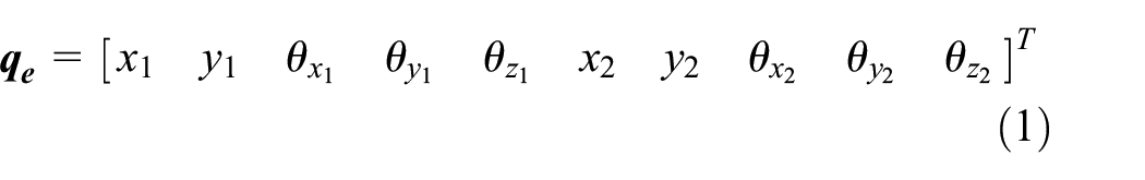
The shaft of the rotor-bearing system is divided into finite shaft segments, each of which is treated as Timoshenko beam element. As shown in Figure 1, each element has two nodes and each node has five degrees of freedom, x1, y1,

Schematic diagram of Timoshenko beam element.
Letting the length of beam element be L and any section length be s, the displacement of any section in the element is expressed by the product of the shape function and the displacement of node
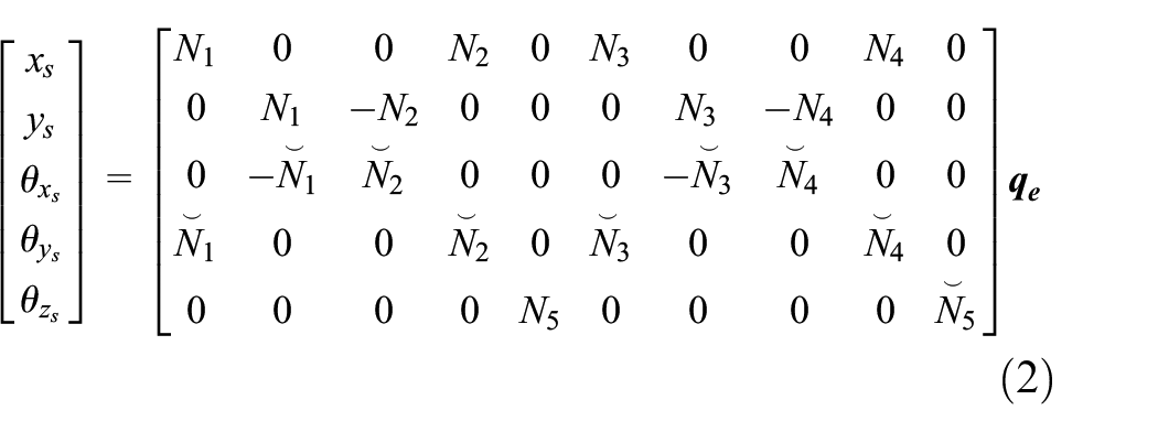
where
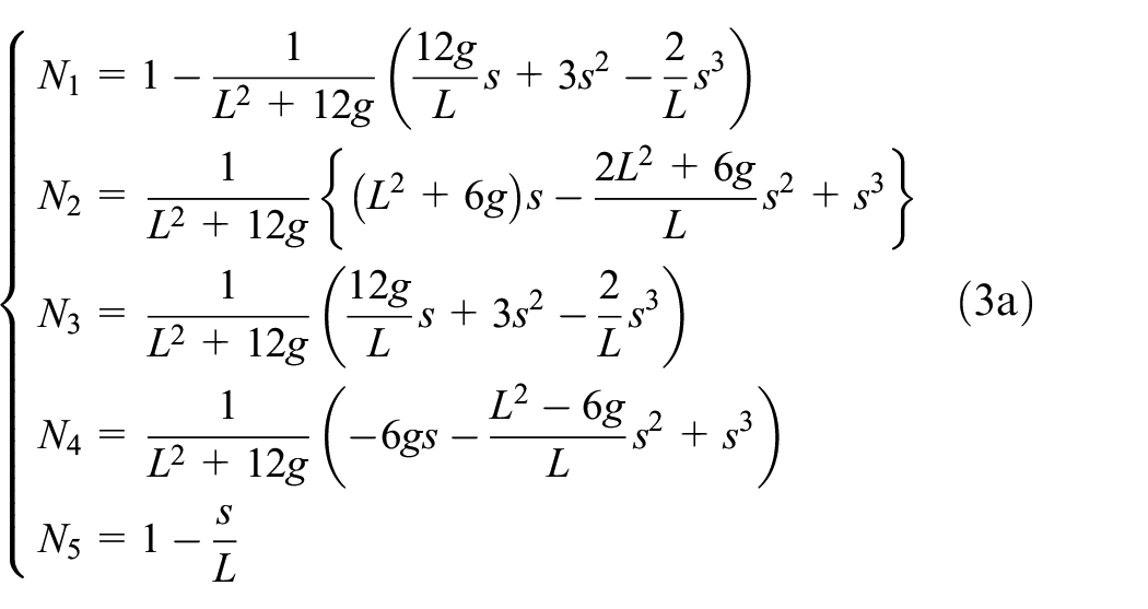

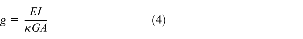

where κ is the shear coefficient of shaft section, μ is the Poisson’s ratio of shaft material, E is the elastic modulus of the beam, I is the moment of inertia, G is the shear modulus, A is the cross-sectional area of beam element. The expression of shape function can be obtained by substituting equation (5) into equation (4) and then into equation (3), and the displacement of any section in the beam element can be obtained.
The total strain energy of beam element can be expressed as

Substituting equations (2)–(5) into equation (6) leads to the strain energy in the form of matrix
where


The total kinetic energy of the beam element can be obtained

Substituting equations (2)–(5) into equation (10) leads to the kinetic energy in the form of matrix. The total kinetic energy can be written as

where


Letting the inner diameter of the hollow shaft segment ds be r0 and the outer diameter be ri, the gyro matrix of the hollow shaft beam element can be obtained through substituting the kinetic energy increment generated by the rotation of the infinitesimal segment around the diameter of the rotating shaft into the Lagrange equation.
The moment of inertia of the diameter for the infinitesimal segment dId can be expressed as

The kinetic energy increment of the diameter of the infinitesimal segment dT is expressed by

Equation (15) is integrated from 0 to L along the length of the beam element, and the kinetic energy can be obtained
The following expression is introduced

Substituting equations (2) and (17) into equation (15) leads to

According to the Lagrange equation,


Substituting equation (17) into equation (20), the gyro matrix of beam element can be derived


Disk model
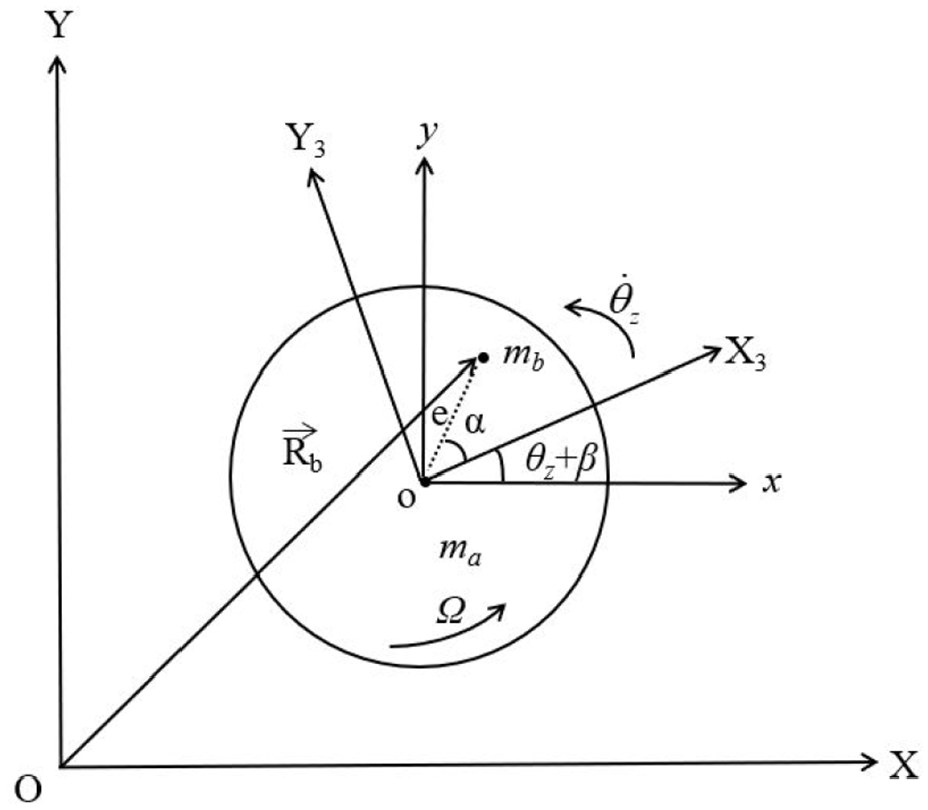
The motion of the disk can be decomposed into the translational motion and rotational motion. The translational motion is the combined motion of the horizontal and vertical directions. The rotation of rotor can be decomposed into the autorotation around the rotor’s center line and the revolution around the static center line. Letting the spin velocity be Ω, and then after time t, the rotation angle β is Ωt. The fixed coordinate system OXYZ of the disk is established, as seen in Figure 2. The OXYZ is rotated around the X axis to generate OX1Y1Z1, and then OX1Y1Z1 is rotated around the Y1 axis to generate OX2Y2Z2. The final coordinate system OX3Y3Z3 is obtained by means of rotating OX2Y2Z2 by (β + θZ) around the Z2 axis.

The coordinate transformation.
The angular velocity of rotation for disk around each axis of Coordinate system OX3Y3Z3 is expressed in the form of the parameters under the fixed coordinate system OXYZ

where

The translational kinetic energy and rotational kinetic energy of the non-eccentric disk can be expressed as


where Jd is the diameter moment of inertia of the disk, Jp is the polar moment of inertia, ma is the mass of the disk.
Substituting equation (24) into equation (26), the expression of rotational kinetic energy in the fixed coordinate system can be obtained
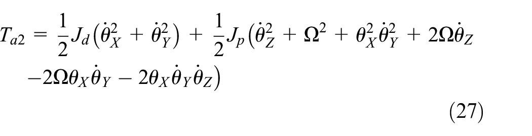
The total kinetic energy of the non-eccentric disk is the sum of the translational kinetic energy and the rotational kinetic energy, its expression is written as

Lagrangian equation of dynamic system without damping is expressed as

where

Substituting equations (25) and (27) into equation (28) leads to the total kinetic energy Ta, and then the dynamic equation of the disk without eccentricity is obtained after substituting Ta into equation (29).
The rotor will whirl when the mass of the disk is unevenly distributed. The motion forms of the rotor in the cross section of the shaft are shown in Figure 3. The whirling forms of the rotor can be decomposed into the autorotation of the rotor around the axis of its own structure and the revolution around the center line of the support. As shown in Figure 3(a), the centrifugal force and the tangential forces are produced due to unbalanced mass of the rotor in the process of autorotation. It can be seen from Figure 3(b) that the rotation center of the rotor deviates from the axis center to produce two directions of inertial force in the process of revolution.

Whirling forms of the rotor: (a) autorotation and (b) revolution.
The rotation of the disk around the axis of its own will cause the rotor to be subjected to centrifugal force and tangential force. The resultant force of the two forces at the center of mass causes the rotor to bend laterally. At the same time, the whirl of the rotor will produce an inertial force which will cause the rotor to twist. Therefore, when the rotor has an eccentric mass, the rotor will have a bending-torsion coupling vibration during operation.
The model of the disk element with eccentric mass is shown in Figure 4. The translational coordinate system of the disk centroid is Oxy; mb is the eccentric mass;

where

where

Model of the eccentric mass coupling element.
Lagrange equation is as follow

where
Substituting equation (33) into equation (34), ignoring the higher order infinite small amount, the dynamic equation of the eccentric mass element can be obtained as

where Mb, Cb and Kb are the mass, damping and stiffness matrices for the eccentric mass element,


The mass matrix of eccentric disk element is got by combining the mass matrices of non-eccentric disk element and eccentric mass element. The dynamic equations for the eccentric disk element can be expressed as

where


It can be seen from equations (39) and (40) that the bending vibration and torsional vibration of the rotor are coupled with each other through the inertia matrix and the damping matrix.
Nonlinear oil film force of sliding bearing
When the nonlinear dynamics of the rotor is studied, the influence of the oil film force on the displacement needs to be considered. In this study, the short bearing is adopted, the assumption is made that the oil film satisfies the Gumbel oil film boundary condition, that is, there is a complete oil film in the convergence zone of the oil film gap, and the oil film in the diffusion zone is completely broken. In order to analyze the physical cause of the nonlinear oil film force, the schematic diagram of the sliding bearing is drawn, as shown in Figure 5.

Schematic diagram for thickness and pressure of the oil film.
In Figure 5, O and O1 are the geometric centers of the bearing inner liner and journal respectively,
In order to simulate the complex oil film force, the classical Capone circular bearing theory is adopted to calculate the dimensionless nonlinear oil film force in the radial and tangential directions and the expressions are shown as follow 39 :
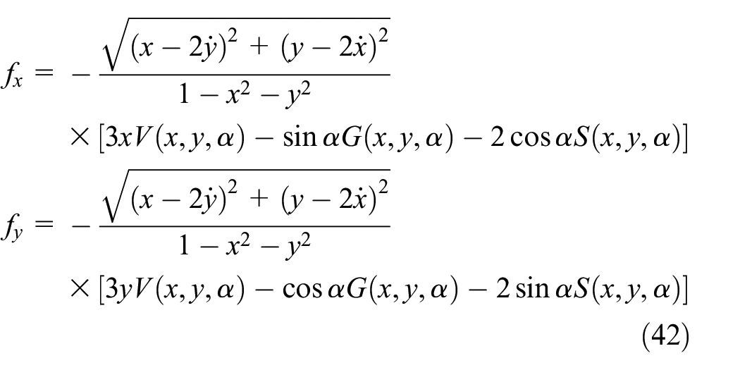
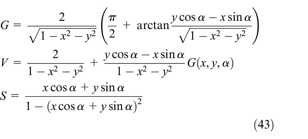
From the equation (43), it can be found that the oil film force on the journal is closely related to the displacement and velocity of the journal in the radial and tangential directions, and the initial positive pressure angle of the oil film, and the oil film force has strong nonlinearity. The dimensionless nonlinear oil film force of the journal can be calculated by applying equation (42) on the node where the sliding bearing is located.
Bending-torsion coupling dynamic equation of rotor system
If the rotor-bearing system has N nodes, then the system is composed of N−1 beam elements. The bending-torsion coupling dynamic equation of the rotor-bearing system is expressed as

where

The finite element model of rotor-bearing system is shown in Figure 6. The total length of the rotation shaft is 0.7 m and the corresponding diameter is 0.02 m; the length of each beam element is 0.05 m. There are 14 beam element matrices assembled to obtain the total stiffness matrix, total mass matrix and gyro matrix of the shaft; and then the coupling mass matrix, stiffness matrix, damping matrix and gyro matrix of the disk 1 and the disk 2 are loaded onto the matrix of the corresponding nodes of the shaft. The sliding bearings are at node 2 and node 13 respectively, and the nonlinear oil film force derived in section “Nonlinear oil film force of sliding bearing” is loaded into the generalized force vector of the corresponding node. Considering the unbalanced force of the disk and the gravity of the rotor-bearing system, the bending-torsion coupling dynamic equation of the unbalanced rotor-bearing system is established.
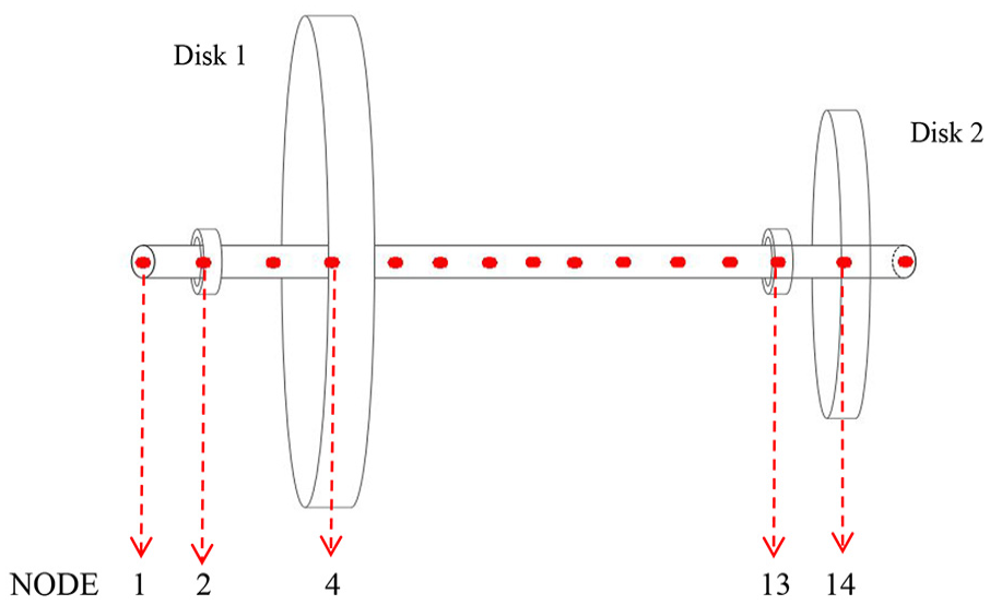
Finite element model of the rotor-bearing system.
The materials for the disk and the shaft are the same, and the parameters of the rotor-bearing system are shown in Table 1.
Parameters of the rotor-bearing system.

Verification of model developed
In order to verify the accuracy of the theoretical model developed in this paper, the general software ANSYS is used to establish the beam-mass model with the same parameters as the theoretical model. On the one hand, the critical rotational speed of the rotor system is calculated by ANSYS Modal module. On the other hand, the eigenvalue of equation (44) is calculated by Matlab programming, the critical speed of the rotor system can be obtained.
By comparing the first two order critical speeds calculated by the two different approaches, the accuracy of the theoretical model established in this study is verified.
Calculation of critical rotational speed based on FEA
ANSYS is used to calculate the critical rotation speed of the rotor system. Modal module in ANSYS is applied to establish the model of rotor-bearing system whose parameters and constraints are the same as the theoretical analytical model built in this paper, as shown in Figure 7. The process and setting for finite element modeling are as follows. The shaft is established by Beam 188 element; the rigid disk is equivalent to the mass point and built by the Mass 21 element; the Combi 214 spring element is added at the corresponding node to simulate the rotor support. The bearing is equivalent to the corresponding stiffness and damping which are obtained by simplifying the nonlinear oil film force46,47 in equation (42), the support stiffness is 5 × 10⁷ N/m and the damping is 1000 N s/m; the axial motion of the shaft is constrained by remote displacement. The Campbell plot is calculated, as shown in Figure 8.

Modeling of shaft-disk-bearing system based on ANSYS.

Campbell plot calculated by ANSYS.
Calculation of critical rotational speed based on the theoretical model
If the state variable is equation (46), the differential equation of motion for the rotor-bearing system can be written as equation (47).


where

In equation (48),

Campbell diagram calculated by Matlab programming.
Comparison of calculating results
The results of the finite element method (FEM) and the results of the theoretical modeling approach (TMA) are compared, as shown in Table 2. The maximum error of the natural frequency calculated by the two methods is only 0.56%, indicating that the theoretical calculation results are in good agreement with those of the finite element calculation. The comparison verifies the correctness of the model established in this paper. Based on the validated model, the analysis of bending-torsional coupling vibrational characteristics for the rotor system will be conducted in the following sections.
Comparison of critical speed.

Bending-torsional coupling vibration characteristics of rotor system with imbalance
Effect of rotating speed
The rotation speed is one of the most basic parameters of the rotor system. The dynamic characteristics of the rotor-bearing system with imbalance will be analyzed in this section. Considering that the two disks with eccentricity have similar characteristics in the vibration analysis, disk 1 is selected as the research object. For investigating the effect of the rotating speed on the dynamic characteristics of the system, the speed range of 1000–25,000 rpm for the rotor is chosen, the eccentric phase difference

The waterfall diagram of disk 1 with bending-torsion coupling: (a) waterfall diagram of bending vibration and (b) waterfall diagram of torsional vibration.

The waterfall diagram of disk 1 without bending-torsion coupling: (a) waterfall diagram of bending vibration and (b) waterfall diagram of torsional vibration.
The waterfall diagrams of the bending and torsion vibrations are shown in Figure 10(a) and (b), respectively. It can be seen From Figures 10(a) and 11(a) that the bending vibration mainly excites the 1× frequency of the rotor, and the bending amplitude considering the bending-torsion coupling is only slightly larger than that of without bending-torsion coupling, and the amplitude at the 1× frequency is only increased by 0.93%. By comparing Figures 10(b) and 11(b), it can be seen that when considering the bending-torsion coupling, the bending vibration will excite the torsional vibration at the 0.5× frequency, the reason for this is related to the half-speed whirl of the oil film bearing. When the bending-torsion coupling is not considered, the system has no torsional vibration due to the absence of external torsional excitation.
In order to study the influence of bending-torsion coupling on bending vibration and torsional vibration at different rotating speed, the unbalance response of the rotor system is shown in Figure 12. By applying Z-score normalization, the different types of vibration response data are unified onto the same scale, providing a reliable foundation for subsequent analysis and comparison.

Effect of bending-torsional coupling on bending vibration and torsional vibration: (a) comparison of bending responses and (b) comparison of bending and torsional responses.
The specific method of Z-score normalization is described as follows. The formula for normalizing the vibration data is given below:

where Zi is the standardized value of the i-th vibration data point, Xi is the i-th vibration data point with a total number of N, μ is the mean value of the vibration data, it can be written as

σ is the standard deviation of the vibration data, it can be written as

The radial bending displacement curves of the disk 1 with and without bending-torsion coupling are compared, as shown in Figure 12(a), and the bending vibration response and torsional vibration response are standardized by Z-Score and are compared, as shown in Figure 12(b). In Figure 12(b), the bending vibration response and torsional vibration response are processed by the Z-score standardization formula, and the standard values that can be used for comparison are obtained. The dominant vibration response can be judged by comparing the size of the standard value.
As shown in Figure 12(a), the bending displacement curve with bending-torsion coupling basically coincides with the bending displacement curve without coupling, this indicates that the torsion vibration has little effect on the bending vibration. As can be seen from Figure 12(b), the bending vibration dominates in the low speed range of 0–10,500 rpm, while the torsion vibration is almost negligible; near the first order torsional critical speed (10,500–13,070 rpm), the torsional vibration is predominant; when the speed increases to higher speed range (13,070–18,100 rpm), the bending vibration dominates in the overall vibrations again; when the rotational speed exceeds 18,100 rpm, the weight of the torsional vibration increases substantially in the total vibrations. In engineering practice, the influence weight of the bending or torsion vibrations in the total vibrations can be determined according to the working speed range, and then more targeted measures for vibration reduction can be taken.
Effect of eccentricity
The eccentricity refers to the distance between the centroid and geometry center of the rotor, it is an important internal parameter for the coupling of the bending and torsional vibrations of the rotor. In general, the greater the eccentricity is, the stronger the coupling effect of bending and torsion is. For studying the influence of eccentricity on the bending and torsion vibrations under coupling and no coupling, the eccentricity e = 0.5, 0.6 and 0.7 mm respectively are chosen to obtain the bending and torsional response maps for the disk 1 with the increasing of rotational speed, as shown in Figures 13 and 14. As can be seen from Figure 13, regardless of whether the bending-twist coupling effect is considered, the eccentricity does not change the first and second bending critical speeds, but changes the bending vibration amplitudes at first and second critical speeds. For the first order bending critical speed, the larger the eccentricity is, the smaller the vibrational amplitude under the critical speed is; for the second order critical speed, the eccentricity is positively correlated with the vibration amplitude. As can be seen from Figure 14, considering the bending-torsion coupling, when the speed is at first torsional critical speed, the larger the eccentricity is and the smaller the torsional vibration is; when the speed is at the second and third critical speeds, the larger the eccentricity is and the larger torsional vibration is. Without considering the bending-torsion coupling, there is no torsional excitation, hence the torsional vibration does not exist, Figure 14(b) presents a straight line.

Comparison of bending response for disk 1 with different eccentricity: (a) with coupling and (b) without coupling.

Comparison of torsional response for disk 1 with different eccentricity: (a) with coupling and (b) without coupling.
In order to intuitively show the influence of eccentricity on the bending and torsional vibrations, the curves of the vibration responses for disk 1 at different rotational speeds is shown in Figure 15 under the eccentricity range of 0.5–1 mm. In Figure 15(b), there are some curve intersection points which show that the vibration responses of the rotor with the same eccentricity have the same torsional angular velocity at different speeds; in contrast, there are no such intersection points in Figure 15(a), indicating that the vibration responses of the rotor with the same eccentricity have different radial bending displacements at different speeds. The difference between bending vibration and torsional vibration is of great significance to the analysis of bending-torsion coupling characteristics. From Figure 15, it can be seen that in this range of small eccentricity, with the increase of the eccentricity, the bending vibrational response increases linearly, and the torsional vibrational response increases nonlinearly. The main reason for this phenomenon is that the eccentricity is the internal factor of the bending-torsion coupling of the rotor. From equation (39), it can be seen that the inertia matrix and damping matrix of the rotor generate the bending-torsion coupling through the eccentricity. The greater the eccentricity, the more obvious the interaction between bending and torsion is, accordingly the greater the torsional vibration caused by the eccentric mass is.

Vibration response of disk 1 with the change of eccentricity: (a) bending vibrational response and (b) torsional vibrational response.
Effect of the initial eccentric phase difference
For dual-disk rotor system, there is a line between the centroid and the geometric center of each disk, and the angle between these two lines of the two disks is called the initial eccentric phase difference. The research on the influence of this parameter on the bending-torsion coupling characteristics is scarce, but for common rotor system with blades, the installation error of blades will cause this parameter to change in a large range, this will have a greater influence on the dynamic characteristics of the rotor. Hence, the influence of the initial eccentric phase difference on the bending-torsion coupling vibrations will be investigated in this section.
Figure 16 is the schematic diagram of the initial eccentric phase difference of rotor system with the two disks. The line between the centroid and geometric center of disk 2 is shown as a red line on the right disk in Figure 16, the corresponding line of disk 1 is shown as the red line on the left disk in Figure 16, the angle of the two lines is the initial eccentric phase difference, the angle is 0°, 30°, 60°, 90°, 120°, 150°, 180° respectively, the curves of the effect of the initial eccentric phase difference on the rotor vibrations can be obtained, as shown in Figure 17.
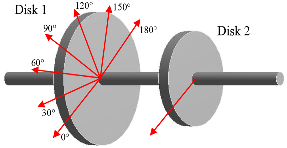
Initial eccentric phase of two disks.

The vibration comparison of disk 1 under different initial eccentric phase differences: (a) comparison of bending vibration and (b) comparison of torsional vibration.
As can be seen from Figure 17, the initial eccentric phase difference has obvious effects on both the bending and torsional vibrational responses. When the initial eccentric phase difference is π, the bending vibrational response is very small, and the rotor system is more stable. The reason for this phenomenon is that, when the initial eccentric phase difference is π (assembly in the opposite direction), and the two unbalanced forces of the two disks are in opposite directions, this will offset a part of the unbalanced excitation force, resulting in a smaller vibration. In contrast, when the initial eccentricity phase difference is 0 (assembly in the same direction), the vibrational response is the largest, because the eccentric phase difference of 0 means that the directions of the two unbalanced forces on the two disks are the same, this will increase unbalanced excitation force of the rotor, leading to larger vibrations. Under other initial eccentric phase differences, the vibration response decreases as the initial eccentric phase difference increases. Therefore, in the practical engineering, when the rotor system with multiple bladed disk is installed, the same direction assembly or small initial eccentricity phase difference should be avoided to ensure the safe and stable operation of the rotor system.
Conclusions
Considering the nonlinear oil film force of sliding bearing and gyroscopic effect of the rotor system, the influence of the rotational speed, the eccentricity and the initial eccentric phase difference on the bending-torsion coupling vibrations is investigated in this paper. The corresponding matrices of the shaft and the disks are derived by Lagrange equation; the analytical formula of Capone oil film force is obtained based on the short bearing theory, the theoretical analytical model of bending-torsion coupling rotor system with two disks and sliding bearings is developed, and its correctness is verified by finite element analysis. It is innovative to study the transfer mechanism of the initial eccentric phase difference for the double discs on the nonlinear vibration responses. The main conclusions are as follows.
(1) Considering bending-torsion coupling, the torsional vibration will be excited at 0.5× frequency by the bending vibration, the reason for this is related to the half-speed whirl of the oil film bearing; when the bending-torsional coupling is not considered, the system has no torsional vibration. The torsional vibration has little influence on the bending vibration.
(2) The influence of rotational speed on the vibration characteristics of bending-torsion coupling is studied. The torsional vibration has very little effect on the bending vibration. The bending vibration dominates in the low speed range of 0–10,500 rpm, and the contribution of torsion vibration to the total vibration is almost negligible; near the first torsional critical speed of the system (10,500–13,070 rpm), the contribution of torsional vibration to the total vibration exceeds the bending vibration; when the speed rises to the higher speed range (13,070–18,100 rpm), the bending vibration dominates in the total vibration again; when the speed exceeds 18,100 rpm, the weight of torsional vibration in the total vibration increases greatly. In engineering practice, the influence weight of bending vibration or torsion vibration can be determined according to the working speed range, and then more targeted vibration reduction measures can be taken.
(3) The influence of eccentricity on bending and torsional vibrations is investigated. The eccentricity does not change the first and second bending critical speeds, but changes the vibration amplitudes at the first and second bending critical speeds. For the first bending critical speed, the larger the eccentricity is, the smaller the amplitude at the bending critical speed is; for the second bending critical speed, the eccentricity is positively correlated with the bending vibrational amplitude. Considering the bending-torsion coupling, when the speed is at first torsional critical speed, the larger the eccentricity is, the smaller the torsional vibration is; when the speed is at second or third torsional critical speed, the larger the eccentricity is, the larger the torsional vibration is.
(4) The initial eccentric phase difference has apparent effects on both the bending and torsional vibrational responses. When the initial eccentric phase difference is π, the bending vibration response is very small and the rotor system is more stable, while the vibrational response is maximized at the initial eccentric phase difference of 0. Under other initial eccentric phase differences, the vibrational response decreases with increasing of the initial eccentric phase difference. Therefore, in practical engineering, when installing a rotor system with multi-blade, the same direction assembly or small initial eccentric phase difference should be avoided to ensure the safe and stable operation of the rotor system.