
Abstract
This paper proposes a design methodology for the regulation mechanism of compression system of a variable cycle engine. Taking the simultaneous work mode of all valves in operation into account, the movement of mode selector vales might be reduced to that of a slider-crank linkage. By analyzing the two extreme working conditions of the slider-crank linkage, we obtain the excellent mechanism in geometry. Replacing all sliders with one integrated floating ring in structure, the mode selector valves can be driven by one source of hydraulic system. This fulfills the design of the regulation mechanism in movement. However, to meet the sealing requirement of a circular space, the regular octagon is used to approximate the circle of duct. Eight sectors of the truncated cone profile are attached with the sides of the moving octagon and the fixed octagon through eight curved plates (links) correspondingly. To satisfy the limited space of an engine, we designed a double parabolic strengthening structure to minimize the internal stress resulting from the offset of cylinder. Both theoretical analysis and finite element method simulation validate the strengthening structure in improving the working condition of the hydraulic cylinder. This design methodology from geometry to internal stress analysis might be generalized to the design of other mechanical systems.
Keywords
Introduction
The concept of a variable cycle engine is illustrated in Figure 1. 1 It was first investigated in 1976 by using the small-bypass-ratio variable cycle engine. 2 Variable cycle engines can adjust the thermal cycle parameters of the engine through flexible flow control while overcoming the conflict between large unit thrust and low fuel consumption. 3 During the transient, large heat flow between the engine metal and the working gas will lead to a large heat transfer and affect the component and whole engine performance. 4 Great efforts have been made to the establishment of non-adiabatic component performance maps for component characteristics change effect. A compact flame holder and injection device with a rear variable bypass injector were designed under variable inlet conditions. 5 The inlet aerodynamic parameters were investigated to match the law of bypass ratio and the combustion characteristics. Through geometry adjustment technology, the engine combusts more efficiently under low-temperature inflow conditions, thereby improving the engine efficiency. 6 A key feature of the cascade absorption-compression refrigeration system for multi-temperature cooling is the innovative system design featuring a two-stage compression, which shows superior performance in energy efficiency and cost-effectiveness compared to using multiple compressors. 7 Therefore, Kim et al. 8 investigated the exhaust thermal management by investigating the application of variable valve actuation. They proposed four variable valve actuation strategies with unprecedent level of rigor, employing a model-based approach that enables extended insights beyond stand-alone testing. A modulated pre-swirl system based on the adjustment of the vane-shaped nozzle is proposed to overcome the flow nonuniformity in the circumferential air supply in design and subsonic cruising conditions. 9 Increasing the number of pre-swirl nozzles could significantly improve the flow adjustment efficiency and performance of the modulated pre-swirl system. Therefore, it is one of the most promising engines that combine the advantages of turbojet engine and turbofan engine. 2 With a regulation mechanism, the variable cycle engine realizes an appropriate energy distribution among various airflow paths to meet the performance requirements of the power system for complex flight tasks. 10 However, more complex mode selector valve structure should be proposed to adapt the flexible requirement in operation. Generally speaking, the variable cycle compression system often consists of a mode selector valve at least, front variable bypass and rear variable bypass injector to direct the flow due to various requirements.2,11 Consequently, the challenge of design is how to provide two-mode working selector valve structure for both continuous working conditions without any aerodynamics shock. More scholars have proposed a lot of innovative designs for different mode selector valves in the past decades.

Schematic diagram of a variable cycle engine.
The mode selector valve is used to transform the configurations between single and double bypass modes.10–12 When mode selector valve is turned on during the double bypass mode, only a portion of the fan air will go through the outer bypass. When mode selector valve is turned off during the single bypass mode, all of the fan air will go through the inner bypass. 13 Therefore, the regulation mechanism of turbine compression system for variable cycle control plays a vital role to improve the performance of an aeroengine. 14 The position and structure of a compression system of the engine is illustrated in Figure 2.

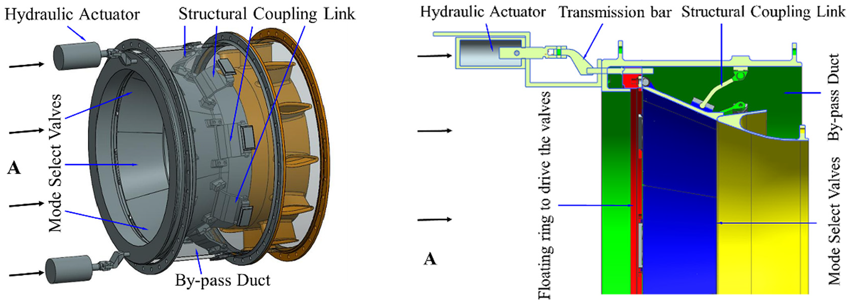
Section view of the compression system for an aeroengine.
This paper focuses on the design of regulation mechanism to control the open and closure of mode selector valves in the compression system for variable cycle control to adapt the working conditions of high temperature, high speed and high pressure with a focus on minimizing the largest internal stress and strain. From the viewpoint of engineering application, the design of any component is subjected to a lot of constraints which might be constructed according to the engineering design requirements. Combined with appropriate methods, constrained problems can be transformed into unconstrained optimizations. 15 Therefore, this paper will first discuss the geometry design of the regulation mechanism for the mode selector valves by considering the real constraints from a variable cycle engine. Then, it will discuss the internal stress and the means to minimize its ill-effect.
Synthesis of the regular octagon linkage
The speed, pressure and amount of airflow cannot be controlled without mode selector valves in the traditional structure of the compression system shown in Figure 2.2,16 Therefore, a regulation mechanism to control the airflow is required to adjust the bypass ratio to control the amount of airflow to pass through the internal and external bypass ducts.17–19
It is the general idea to split the internal and external bypass ducts by a regulation mechanism in the turbine compression system shown in Figure 3. The airflow will only pass through the second bypass duct when the regulation mechanism is closed, and the airflow will pass both the first and second bypass ducts when the regulation mechanism is open. Generally speaking, the thermo-mechanical coupling should be investigated in great detail to analyze the load distribution. 20 However, how to design the regulation mechanism to adapt the circular duct is the major challenge.
Regulation mechanism in the compression system of a turbine.
Since the pressure, temperature and speed of airflow are all very high in the compression system, the requirement of opening and closing of the mode selector valves by the regulation mechanism is critical. Of course, we can use a regular polygon to replace the circular inlet of the duct approximatively. Therefore, the problem becomes how to approximate a circle from the side view A in Figure 3. To fulfill the opening and closing functions of the mode selector valves effectively, a regular equilateral polygon is a good candidate to approximate the circular inlet of duct in geometry.
Theoretically speaking, the more sides the regular polygon has, the more precise the circular space will be approximated. Figure 4 illustrates the first six regular equilateral polygons to approximate a circle. Of course, the proper number of sides should be selected in accordance to the restrictions from other physical requirements such as the manufacturing and assembly technology and restrictions.

Polygons to approximate a circle.
Here, we select octagon mechanism to control the opening and closing of the mode selector valves by taking the necessary strength of connection between each valve and the floating ring and the by-pass duct. Eight sectors of the truncated cone profile are attached with the sides of the moving and fixed octagons through eight curved plates correspondingly. The actuation is added to the floating ring and then the ring pulls or pushes the mode selector valves to open or close the bypass duct simultaneously. In practice, the floating ring works like a slider C shown in Figure 5. Therefore, the upper and lower cylinders in Figure 3 provide the guidance of the movement of the floating ring (slider C shown in Figure 5). As a result, each sector can be proposed as a slider-crank linkage shown in Figure 5 in movement and the design of the regulation mechanism is turned into the parameters optimization of each slider-crank linkage.

A slider-crank mechanism.
The general requirement of the mode selector valves is that all valves must be opened or closed simultaneously. When they are working under the closed configuration, the second by-pass duct is turned off and there is only one by-pass duct at work.18,19 As a result, the design of the mode selector valves is now transformed to the parameter optimization of two-position of a regulation mechanism shown in Figure 5. Next, we will discuss the geometry optimization of the mechanism.
Parameters optimization of each sector of the truncated cone mechanism
Two-position analysis of the slider-crank mechanism
According to the working requirements, there are two prescribed configurations for the slider-crank mechanism, closed configuration (Figure 6(a)) and open configuration (Figure 6(b)). From the closed configuration to the open one, the slider moves from C1 to C2 and the crank AB which replace one mode selector valve rotates from the closed configuration AB1 to open configuration AB2 (Figure 6(c)).

Two-position optimization for the slider-crank linkage (a) closed configuration, (b) open configuration, and (c) displacement of the slider-crank linkage from the closed configuration to the open one.
To make sure it works stably in mechanism theory, the dead point at the first configuration with

Coordinate system for the slider-crank linkage.
Therefore, the design of mode selector valves is now simplified to the two-position design of a slider-crank linkage in mechanism theory.
Optimization of link parameters
There are a lot of scholars who have already investigated the position synthesis of linkages. Peon-Escalante et al. investigated the coupler point velocity control of variable input speed servo-controlled four-bar mechanism
21
and position design of the trailing arm bushing on torsion beam suspension.
22
A coordinate frame shown in Figure 7 is established by setting the origin on the external by-pass duct that is superimposed with the fixed rotational joint A and letting x point leftward and y upward. z-axis is determined in accordance with the right-handed rule. The subtended angle between the x-axis and link BC is θ. In the coordinate system, suppose that the position vector of the driving slider C is

where l is the length of link BC. At the second working position, there is
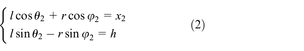
The preconditions for the design are that the distance d and h shown in Figure 7 are both specified because of the size of the external duct. It is the objective of optimization to minimize the travel of slider C aiming at prompt response for the slider-crank linkage. The dead point at the close configuration with
From equations (1) and (2), we gain the displacement of the driving slider, s:

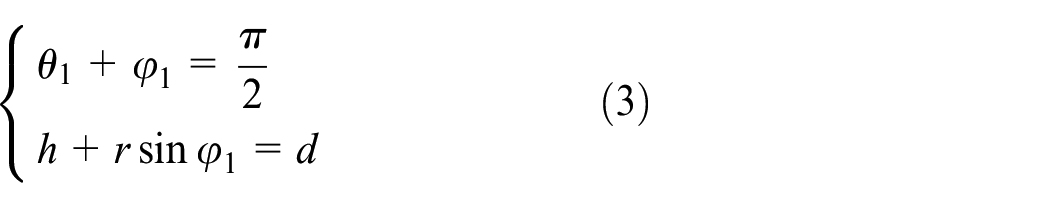
which is subjected to the combination of equations (2) and (3):

where r is the length of the crank. Hence, the optimization problem is now transformed to

where λ1, λ2 and λ3h are Lagrange coefficients. Here we particularly set λ3h for the sake of simplifying the analysis below. The necessary conditions for s to get its extremes are that

Associating equations (5) and (7), we can find the solutions of θ1, θ2, φ1, φ2, l and r to let the displacement of driving slider be the minimum:

To simplify the analysis and the design of the mechanism, we set parameters being dimensionless by dividing h on both sides of equations which contain length variables and let

As a result, equation (8) is now expressed by

Equation (10) consists of nine transcendental equations which often result in a lot of different solutions. Therefore, we adopt numerical method to find the reasonable solutions by considering the real constraints. By specifying the second configuration of the slider and crank mechanism in accordance with the real requirement,
Feasible solutions.

Since it is impossible to get the analytical solutions for the transcendental equations, we here only give the numerical ones by programming at MATLAB. Table 1 presents 13 feasible solutions to satisfy the primary requirements of the movement of the slider-crank mechanism through dimensionless optimization. To reduce the actuating force further, we might select solution 13 because the displacement of the cylinder is the maximum among all solutions which is helpful to reduce the maximum actuation force and the acceleration simultaneously.
Design of mode selector valves
In accordance to the solutions above, we designed the mode selector valves for the compression system. The actuator of each valve is a slider shown in Figure 6. To keep the opening and closing of the mode selector valves simultaneously, we use one floating ring to connect the eight valves together and their corresponding cranks are all jointed with the external duct directly (Figure 8).

Regulation mechanism for the mode selector valves.
As is shown in Figure 8, the transmission system is composed of hydraulic actuator, auxiliary strengthening structure, driving slider and the mode selector valves. The hydraulic actuator is designed specifically for adapting the space inside the external by-pass duct. The transmission bar subjects to very complex loads despite that both sides only undertake pure forces. Suppose the output force of the linear actuator has the tensile force of magnitude of F and direction horizontally to the left. Based on Newton’s third law, there will be an identical force on the other side connected with the driving ring, which has the same magnitude of F, and the direction horizontally to the right. Due to the limitations of the space, there is an offset of h between the two forces, which will generate a counterclockwise moment of magnitude M=Fh. This bending moment acts on the transmission bar to generate tensile stress:
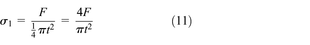
where b is the width of the cross section of the transmission bar and t is the thickness of the bar, and the normal stress resulting from the bending moment, σ b , is

where W is the section modulus in bending and

Hence, the thrust link experiences the additional normal stress that is more than eight times of that of the straight tensile bar due to the step structure with an offset of h > t.
Design of a balance structure to minimize the additional stress and increase the stiffness
To avoid the ill-effect of the step structure on the sealing of hydraulic system because of the additional moment resulting from the offset of the step structure, we proposed a statically indeterminate structure to transfer the additional moment to the external by-pass duct from the step bar shown in Figure 9. When the hydraulic valve moves back, the statically indeterminate structure moves relative to the cage through the rollers, which transforms the sliding friction into rolling friction. The bending moment of the beam at each section varies with the position of the section. 23 For a beam of equal cross-section, the bending section coefficient W is constant, the maximum stresses may be close to the allowable stresses only at the cross-section where the bending moment is at its maximum value. The rest of the sections have smaller moments, the stresses are much lower and the material is not fully utilized. To save materials and reduce their weight, the guidance beam adopts variable cross-section structure so that W changes with the bending moment by keeping the constant normal stress on any cross section. Variable cross-section beam has a larger cross-section where the bending moment is larger and a smaller cross-section where the bending moment is smaller. According to the mechanics of materials, 23 the normal stress calculation of beams with variable cross-sections can still be approximated by the formula of beams with constant cross-sections. When the maximum normal stress on each cross-section of the variable-section guidance beam is equal, it is a beam of equal strength. The axial contact stiffness model of position preloaded ball screw mechanism based on Hertz contact theory is proposed for the optimization design. 24 In what follows, we will establish the stress equation first and then discuss what cross section of the beam is required to satisfy the equal strength design.
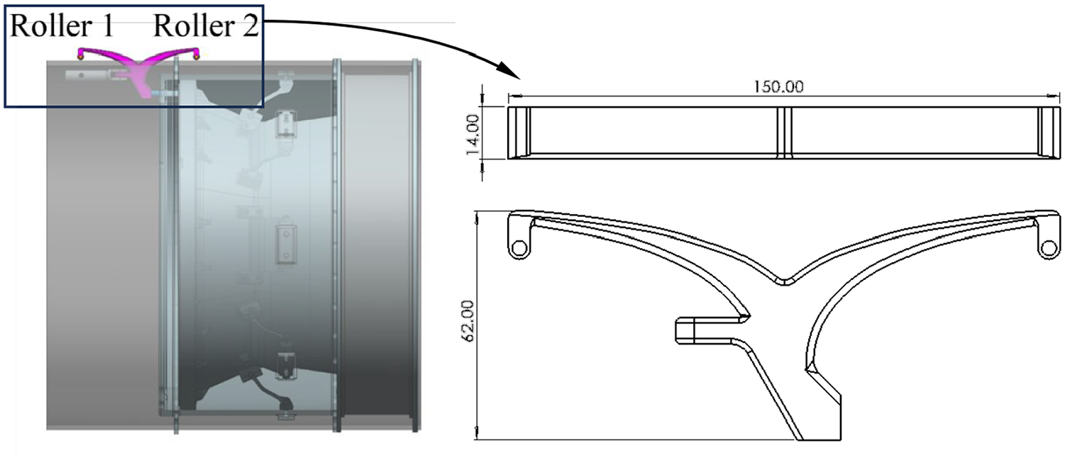
Parabolic strengthening structure for the transmission bar.
Let the bending moment of the beam at any cross section be M(x) and the bending section coefficient of the section be W(x). Based on the above requirement of equal-strength beams, there should be

where [σ] is the allowable stress of the beam. Alternatively,

This is the law of variation of W(x) along the beam axis for an equal-strength beam. According to the equilibrium relationship, we have

where F is the force of the transmission bar, N represents the normal force from the cage to auxiliary strengthening structure, L is the distance from the root of the auxiliary strengthening structure to the action force N. The internal moment in any cross-section is

For a rectangular cross section, the flexural section coefficient, I z , is

where a and b are the height and width of the rectangular cross section, respectively. So, the normal stress in the cross-section is

where y is the distance of a point with respect to the natural plane, the maximum normal stress occurs on the section with the maximum bending moment and is farthest from the central axis:

For rectangular sections,
where [σ] is the allowable stress. Consequently,

In applications, considering various influencing factors, the allowable stress can be obtained

where σ b is the yield limit and n is the safety coefficient. From equation (22), a can be expressed as the function of x:

Equation (24) presents the equation for the cross-section height a(x) as a function of x. From equation (24), we know that the height of the equal intensity section of the strengthening beam satisfies the parabolic equation. To balance the additional moments in forward and backward actuation, a double parabolic structure attached with the beam is designed (Figure 9).
When the cylinder pulls the actuation ring leftward, the additional moment generated from the offset size is balanced by the left parabola beam via roller 1. Vice versa, when the cylinder pushes the actuation ring rightward, the additional moment resulting from the offset size is balanced by the right parabola beam via roller 2. In this way, the cylinder only undertakes the axial force. The double-parabolic beam transforms the additional moment of torque through a slot of the cage to the outside of the engine where there is no working air flow. As a result, both the stiffness of the actuation system and its service life are improved through the strengthening parabola structure shown in Figure 9.
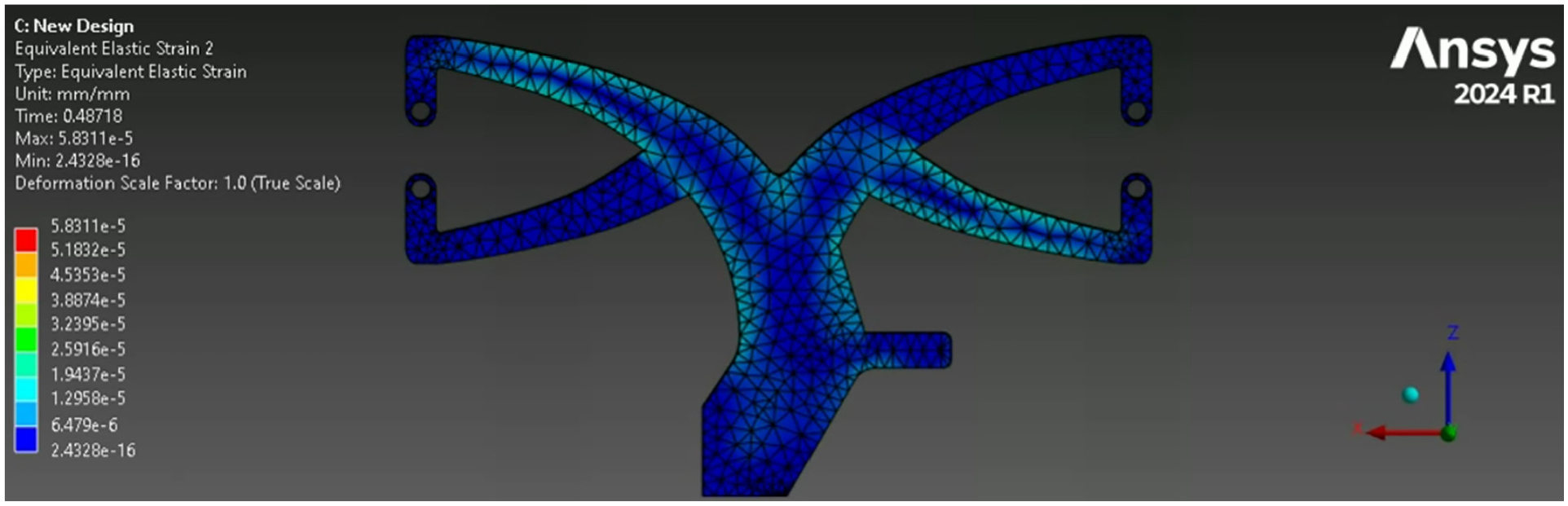
We established the FEM model with the geometry parameters of the transmission bar of t= 13mm, h= 21mm, length of 200mm and force amplitude of F= 170N to evaluate the performance of the parabolic strengthening structures during the actuation left and right. With the strengthening structures, the largest internal stress (Figure 10(a)) and strain (Figure 10(b)), and deflection amplitude in reciprocal actuation (Figure 10(c)) of the transmission bar are all greatly reduced in the simulation. Figure 10(c) indicates that the largest deflection of the transmission bar can be immediately reduced from more than 0.45 mm to less than 0.25 mm after designing a strengthening structure. By properly increasing the stiffness of the strengthening structure, the deflection amplitude of the transmission bar during reciprocal motion may be reduced to 0.2 mm and even lower (Figure 10(c)) which validates the effectiveness of the design in Figure 9.

Simulation and comparison: (a) stress distribution of the parabolic structure in actuation, (b) strain distribution of the parabolic structure in actuation and (c) deformation comparison of the axis of the thrust link with/without parabolic structure in actuation.
To reduce the deformation further, we might design a symmetry structure about the tunnel shell whose strain cloud in pulling process of the cylinder piston is shown in Figure 11. This design reduces the deformation significantly, the maximum of which is less than 0.015 mm.
Simulation of the symmetry strengthening structure.
Consequently, although the symmetry parabolic structure shown in Figure 11 could greatly reduce the maximum internal stress and strain, it is not advisable because of the space occupied below the tunnel shell. Figure 12 illustrates the working process from closing form of mode selector valves to open form. Experiment show that the working process is not very smooth without the parabolic structure because of the bias of the axis resulting from the deflection shown in Figure 10(c). Engineering experience shows that any bias of the axis large than the tolerance of 0.25 mm will severely wear the hydraulic cylinder and therefore reduce its service life.

Primary experiment on the prototype without the strengthening structure.
Based on the above theoretical analysis, simulation and primary experiments on the original prototype without strengthening structure, we decide to improve the regulation mechanism of the mode selector valves with the double parabolic strengthening structure shown in Figure 9.
Conclusions
This paper proposes an innovative design of regulation mechanism for variable cycle compression system of advanced engines. The sealing requirement of the circular duct at high speed, high temperature and high pressure increases the challenges to the design. To approximate the circular space, the regular octagon is selected by considering the physical properties although a lot of other regular polygons are also available in geometry. Eight sectors of the truncated cone profile are attached with the sides of the moving octagon and the fixed octagon through eight links correspondingly. Therefore, each sector can be proposed as a slider-crank linkage in movement and the design of the regulation mechanism is reduced to the position synthesis of a slider-crank linkage. With objective of minimizing the actuating force or maximizing the travel of the slider, we optimized the parameters of the slider-crank linkage for the mode selector valves. However, the limited space does not allow the direct actuation of the jointed sliders by one floating ring after synthesizing the mode selector valve mechanism. Offsetting the cylinder is a feasible selection. But this results in increasing of internal stress of the transmission bar by eight times extremely because of the additional moment of torque during acting left and right. This worsens the overall structural strength, stiffness, sealing of the cylinder and its service time. The innovative design of a strengthening structure to bear such additional moment helps fulfill the requirement of regulation mechanism under the limited space. The design method from geometry to stiffness increasement of the regulation mechanism for a compression system might be used to the design of any other similar mechanical systems.
Footnotes
Appendix
Notation

| Symbol | Notation |
|---|---|
| a | Height of the rectangular cross section of the transmission bar. |
| b | Width of the cross section of the transmission bar. |
| d | Distance between the outer (first) and inner (second) by-pass ducts. |
| F | Force of the transmission bar. |
| h | Offset of slider with respect to the rotational shaft of valve. |
| I z | Flexural section coefficient of a rectangular cross section. |
| l | Length of link BC. |
| L | Distance from the root of the auxiliary strengthening structure to the action force N. |
| M(x) | Bending moment of the beam at the cross section x. |
| N | Normal force from the cage to auxiliary strengthening structure. |
| r | Length of the crank. |
|
|
Position vector of the driving slider C. |
| s | Displacement of the driving slider. |
| t | Diameter of the circular transmission bar. |
| W | Section modulus in bending and . |
| W(x) | Bending section coefficient at section x. |
| y | Distance of a point with respect to the natural plane. |
| φ | Angle between the horizontal line and the crank AB. |
| θ | The subtended angle between the x-axis and link BC. |
| λ | Lagrange coefficients. |
| σ | Stress of the transmission bar. |
| σ b | Normal stress resulting from the bending moment. |
| [σ] | Allowable stress of the beam. |
| ξ | Dimension ratio. |
Acknowledgements
The authors appreciate Mr. Ganaba Harouna and Mr. Kanbodin Kechacoop for their kind assistance in processing some of the diagrams of the article.
Handling Editor: Divyam Semwal