
Abstract
A bi-directional linear ultrasonic motor (LUSM) based on multi-vibration of the piezoelectric (PZT) ceramic are proposed, designed, fabricated, and tested in this paper. The PZT ceramics with parallelogram cross-sections are positioned at both ends of the elastomer. Both torsional and longitudinal vibration modes co-occur when AC voltage is applied to PZT ceramics. In the elastomer, the longitudinal and bending modes are then formed. The motor can work on two hybrid vibration modes by changing the size of the stator and the voltage excitation scheme. The finite element method optimizes the motor design and modifies the motor size. The resonance frequencies of the two modes are extremely near, and the driving foot’s trajectory is acquired to evaluate the design’s reasonableness. A prototype is created, and an experimental investigation of the motor characteristics is presented. The results indicate that under a voltage of 1080 Vp-p, the proposed motor produces a forward velocity and thrust force of 37.04 mm/s and 0.22 N and a backward velocity and thrust force of 36.36 mm/s and 0.21 N.
Introduction
USMs are a novel kind of microactuator with many advantages, such as compact size, 1 rapid response, 2 large torque in the low-speed range, absence of electromagnetic interference,3,4 and self-locking without power. 5 USMs transform the electrical energy into mechanical vibrations of the stator using the inverse PZT effect of PZT ceramics.
According to the difference in operating mode, there are two types of LUSMs: single-mode LUSMs and multi-mode LUSMs. For single-mode LUSMs,6,7 the working mode is generally bending vibration mode to form the vertical pressure and horizontal thrust on the slider. This kind of motor is compact in structure and simple in design, but it has the weakness of small output thrust.6,8
For the multi-mode LUSMs using the hybrid mode,9,10 such as longitudinal-bending (L-B) mode,11–14 longitudinal-longitudinal (L-L) mode, 15 bending-bending (B-B) mode,16–18 longitudinal-torsional (L-T) mode,19,20 et al., matching the frequencies of distinct modes is crucial and difficult during the preliminary design of the motor. The fundamental approach involves changing the frequencies of two essential modes and minimizing the frequency difference by modifying the parameters of the stator. Combining two vibration modes with a phase shift produces elliptical trajectory movement on the driving foot.
In previous works, the d13 and d33 working modes of PZT ceramics are generally adopted to form the vibration modes in the stator. PZT ceramics must be pasted on the bending vibration surface of the stator. The LUSM under this design method needs multiple power sources, and the PZT ceramics will be limited to the placement of the driving parts.
This paper presents and tests a bi-directional LUSM based on multi-vibration of PZT ceramics. The PZT ceramics are attached to both ends of the elastomer with conductive adhesive. Elastomer and its d13 and d15 working modes are adopted to form an L-B hybrid vibration mode in the stator, generating oblique lines on the driving feet to drive sliders linearly. The motor can work in two hybrid vibration modes by changing the size of the stator and the voltage excitation scheme. The finite element method analysis by ANSYS 18.0 for the motor is utilized to verify the operation principle. The trajectory of the driving feet is analyzed analytically and stimulatingly. The motor’s prototype is manufactured, and its vibration characteristics and output performances are evaluated.
LUSM structure
The three-dimensional view of the structure of the LUSM is shown in Figure 1. Figure 2 shows the main geometrical parameters of the proposed motor.

Three-dimensional view of the structure of the stator.

Parameters of the optimized stator.
The motor adopts oblique piezoelectric ceramics, and Figure 3 shows its structure. The main cross-section of the oblique piezoelectric ceramics is a parallelogram, and the silver plating layer covers the end of the oblique piezoelectric ceramics.

Structural diagram of oblique piezoelectric ceramics.
The polarization directions of the four oblique piezoelectric ceramics are all vertically upward. When an oblique electric field is generated inside the piezoelectric ceramic, the horizontal component of the oblique electric field is perpendicular to the polarization direction of the piezoelectric ceramic, causing it to undergo stretching vibration in the horizontal direction. At the same time, the vertical component of the oblique electric field is parallel to the polarization direction of the piezoelectric ceramic, causing it to undergo torsional vibration in the vertical direction. Oblique piezoelectric ceramics can simultaneously excite elastic bodies in horizontal and vertical directions.
This motor mainly consists of a metal elastomer, four PZT ceramics, driving feet, sliders, and bronze electrodes. The bronze electrodes are clamped on the outside of the PZT ceramics for exciting voltage input and creating a fixed condition for the stator. Four PZT ceramics that adopt d33 working mode and d15 working mode are bonded at two ends of the metal elastomer. The polarization directions of PZT ceramics are all in the positive Z-axis direction, and they are used to stimulate the stator’s longitudinal and bending vibrations simultaneously. The driving feet make contact with the sliders and drive them to travel along the X-axis in a linear direction.
Two driving feet are respectively attached to the upper and lower surface of the metal elastomer. The right lower driving foot is at the maximum amplitude on the right side of the second bending mode, and the left upper driving foot is at the maximum amplitude on the left side of the second bending mode.
To make the frequency of the first longitudinal vibration mode as close as possible to the frequency of the second bending vibration mode, we optimized the length of the metal elastic body. The elastic body’s initial length, width, and height dimensions without the driving foot are 42 mm × 10 mm × 10 mm. Considering the compactness of the motor, only by changing the length of the elastic body can the frequency difference between longitudinal and bending vibrations be reduced. The analysis results are shown in Figure 4. Without the drive foot, the size of the stator elastic body is determined to be 46 mm × 10 mm × 10 mm, and the overall size of the motor is 52 mm × 23 mm × 10 mm.

The influence of the length of metal elastomers on the modal frequency difference.
Operating principle
Principle of motion
The motor works on the L1-B2 hybrid vibration mode. Four PZT ceramics can be divided into two groups and be connected with four electrodes: A1, A2, B1, and B2. As shown in Figure 5, the corresponding electrodes excite each PZT ceramic.

Two voltage excitation schemes: (a) the polarizations and arrangements of the PZT ceramics (under the first scheme) and (b) the polarizations and arrangements of the PZT ceramics (under the second scheme).
Two schemes are applied to achieve motor commutation. (1) The first scheme: When the AC voltages are applied to A1 and A2, the oblique electric fields (EA1, EA2) are generated in the PZT ceramics. The first longitudinal and second bending vibration modes formed in the stator are shown in Figure 5(a). In this case, Sliders above and below move backward. (2) The second scheme: When the AC voltages are applied to B1 and B2, the oblique electric fields (EB1, EB2) are generated in the PZT ceramics, as shown in Figure 5(b). Compared with the first scheme, the second bending mode is invariant, and the first longitudinal mode is 180° different. In this case, Sliders above and below move forward.
Under the first scheme, the operation process of the motor in one cycle is illustrated in Figure 6:
(1) The motor generates no deformation at first instant (t = n) T.
(2) When t = (n + 1/4) T, the motor runs along the X-axis in the negative direction in the negative direction of the X-axis to the maximum mode of first longitudinal vibration and reaches the maximum state of second bending mode in the Z-axis direction.
(3) When t = (n + 2/4) T, the motor is stimulated to return to its original status.
(4) When t = (n + 3/4) T, the motor runs along the X-axis in the positive direction to the maximum mode of first longitudinal vibration and reaches the maximum state of second bending mode in the Z-axis direction.

Operation process of the proposed motor in one-cycle.
Thus, the driving feet create an oblique trajectory movement during such operation orders, which can push sliders above and below to move backward.
When the second scheme is adopted, the sliders above and below move forward.
The motor designed in this paper needs only one power source and one PZT ceramic structure to satisfy both longitudinal and bending vibration requirements. The motor’s commutation is realized by applying a voltage to different bronze electrodes.
All PZT ceramics are attached to both ends of the elastomer to arrange the driving feet on the top and bottom surfaces of the elastomer, which makes the structure of the motor compact. Sliders above and below can move in the same or opposite direction by adjusting the position of the driving feet.
Analysis method for driving foot trajectory
The displacement response of the longitudinal vibration of the beam under PZT excitation using the separation of variable method can be expressed as:

The electric field generated in PZT ceramic can be expressed as:

The average field intensity is:

where
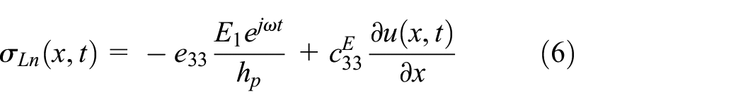
The strain of PZT:

According to the second kind of piezoelectric equation, when only longitudinal vibration is considered, the following equations are obtained:

where,
Strain energy of PZT ceramic:
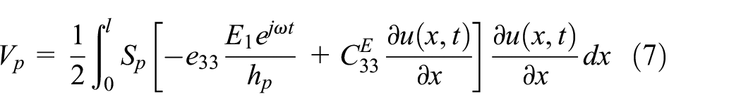
where,

Strain energy of the beam (excluding PZT ceramic):

Total strain energy of beam excited by PZT ceramic:

Assuming that:

where,
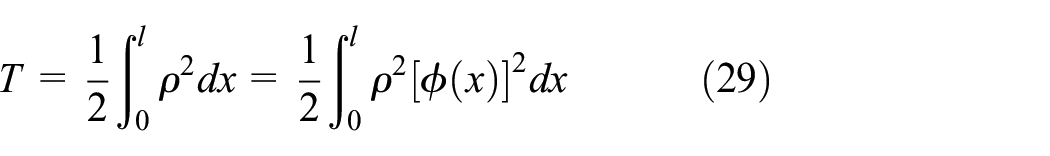
The total kinetic energy of the beam excited by PZT ceramic:

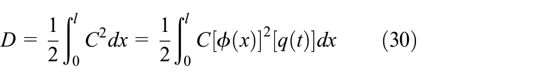
Considering the damping of a uniform beam, the dissipated energy is introduced, assuming that:

where,

Based on the Lagrange equation and the orthogonality of displacement modes, we obtain:

The modal force is:

Then,


where,
Under the condition of fixed end, the mode function of the first longitudinal vibration is:

Then,

The displacement response of the bending vibration of the beam under PZT excitation can be expressed as:

where, n = 2, which represents second bending vibration.
The electric field generated in PZT ceramic can be expressed as:
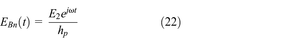
where,
The bending moment of a uniform beam is:

where,
The strain function of the bending mode of the beam can be expressed as:
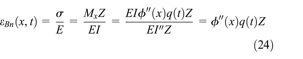
where,
Strain energy of unit volume:

Strain energy of PZT ceramic:

where,
Strain energy of the beam (excluding PZT ceramic):

Total strain energy of beam excited by PZT ceramic:

Total kinetic energy of beam excited by PZT ceramic:
Considering the damping of a uniform beam, the dissipated energy is introduced, assuming that:
Based on the Lagrange equation and the orthogonality of displacement modes, we obtain:

The modal force is:

Then,

Under the condition of fixed end, the mode function of the bending vibration is:

where,

where,

Combing equations (19) and (36), we obtain:
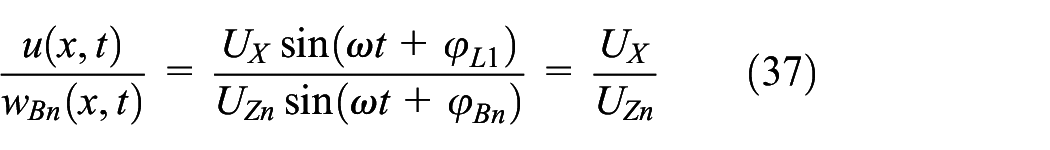
Equation (37) states that a linear relationship exists between the longitudinal and vertical displacement generated on the driving foot.
Simulation analysis
The finite element program (ANSYS 18.0) analyzes the motor’s modal characteristics. The material of the stator is steel (Mass density

First longitudinal vibration and second bending vibration modes of the motor.
Transient analysis is used to analyze the trajectory of the driving foot to evaluate the motion characteristics of the LUSM. The center particle is selected on each foot, and their displacement in longitudinal and vertical directions is extracted. Figure 8 shows the FEM-simulated trajectories of driving feet in one vibration cycle. The trajectory is a narrow elliptical path that approximates an oblique straight line, which is close to the conclusion of equation (37). However, due to the self-vibration of the drive foot, the trajectory is not exactly a straight line but rather a narrow elliptical path.

FEM-simulated trajectories of the driving feet (L1-B2 hybrid vibration mode): (a) the trajectory of the upper driving foot and (b) the trajectory of the lower driving foot.
The FEM-simulated trajectories of the driving feet of the motor working on L1-B2 hybrid vibration mode are shown in Figure 8. The arrows denote the movements’ directions. Two curves in each figure represent the trajectories of the first and second schemes, respectively. The maximum horizontal and vertical displacements of the driving foot are about 6.6 and 3.3 µm, respectively. Under the first scheme, the sliders above and below move backward, which conforms to the operation theory analysis. Under the second scheme, sliders above and below move forward. The maximum displacement of the driving feet under the first scheme is the same as that under the second scheme, which shows that the motor performs similarly under these two schemes.
Experiment
The prototype is created using the parameters presented in Figure 2. Figure 9 demonstrates the final stator prototype of the bi-directional LUSM. Figure 10 shows these devices are the main components of the experimental platform. An amplifier circuit (WF1974) amplifies the electrical signal created by the signal generator and then delivers the AC voltage to the PZT ceramic through the transformer. DC power supply (SPD3303C) supplies power to the amplifier circuit. The System diagram is shown in Figure 11.

The final stator prototype of the bi-directional LUSM.

The main components of the experimental platform.
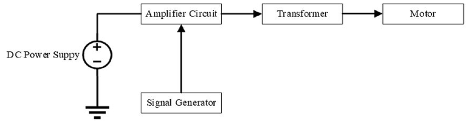
System diagram of the drive circuit.
As shown in Figure 10, the torque spring and guide wheel are used to alter the preload. The fixed stator drives the feet in contact with the slider and drives the movement of the slider through friction. The velocity of the motor-driven slider is measured using photoelectric gates according to the method of averaging multiple measurements.
Analyze the impedance characteristics of the motor prototype. Figure 12 shows the results. The series resonant frequencies for forward and reverse operation of the motor are 33.7 and 33.58 kHz, respectively.

Impedance characteristic analysis of the motor.
Frequency scanning experiments on the motor prototype are conducted by using a scanning laser vibrometer (PSV-400). Figure 13 shows the main device for conducting vibration tests. The experimental results are shown in Figure 14, demonstrating that when the operating frequency is 33.8 kHz, the motor’s amplitude reaches its maximum value. The voltage applied during the experiment is 358 Vp-p, and the maximum vibration amplitude driven is approximately 0.76 μm.

Vibration testing instrument.

Relationship between frequency and amplitude.
The output performance of a motor that depends on high-frequency vibration is intimately related to the frequency of vibration. Two experimental schemes are adopted: (1) An excitation voltage of 1080 Vp-p is simultaneously applied to electrodes A1 and A2 on PZT ceramics to measure their forward velocity. (2) An excitation voltage of 1080 Vp-p is simultaneously applied to electrodes B1 and B2 on PZT ceramics to measure their backward movement velocity.
As shown in Figure 15, with a progressive rise in frequency, the no-load velocity increases and eventually declines independently of the excitation mode. Although the velocity of motor forward and backward drives is slightly different, the no-load velocity reaches its maximum of 37.04 and 36.36 mm/s when the frequency approaches 33.6 kHz. Meanwhile, the driving force is 0.22 and 0.21 N, respectively.
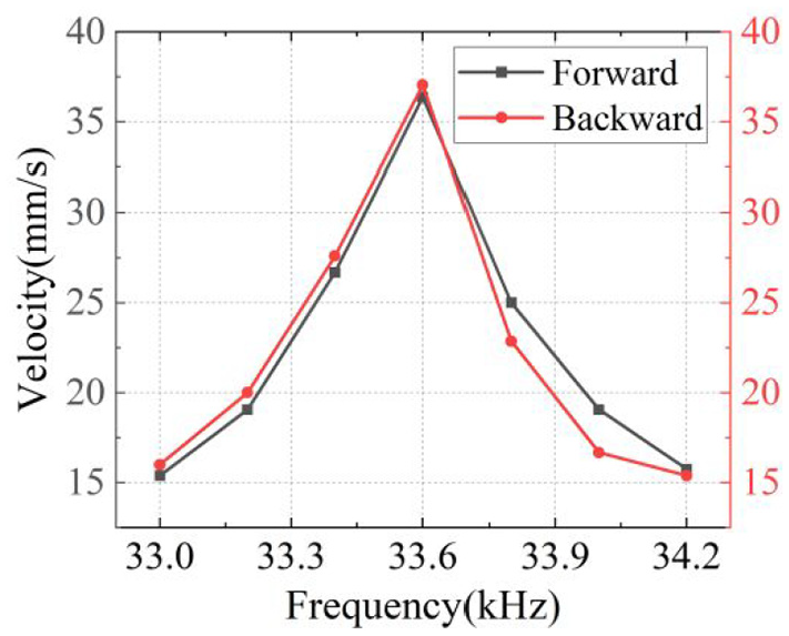
Relationship between frequency and velocity.
This issue has several causes for which the working frequency determined via experiment differs somewhat from that determined through theoretical analysis, including parameter mistakes, temperature changes, and insufficient manufacturing methods.
The output performance of the USM is directly related to the voltage. By altering the voltage, the no-load operating speed of the motor has been evaluated within the same operating frequency of 33.6 kHz. Figure 16 shows the no-load velocity of the USM progressively increases as the voltage supplied to the bronze electrodes increases from 480 to 1080 Vp-p. The no-load velocity reaches its maximum of 37.04 and 36.36 mm/s, respectively, when the voltage applied to Group A and Group B approaches 1080 Vp-p. As the voltage increases, the inverse PZT effect of the PZT ceramic will develop, resulting in a greater degree of deformation of the elastomer, which accelerates the sliders (Table 1).
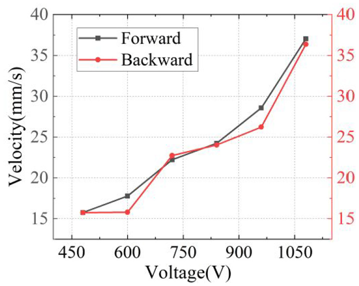
Relationship between voltage and velocity.
Comparison between two excitation schemes.

With different excitation schemes for the PZT ceramic, the LUSM achieves a single motor’s forward and backward motion. Due to different PZT ceramic material parameters, mechanical assembly errors, and other reasons, the velocity and thrust of the motor in forward and backward motion are not consistent but extremely close. The results indicate that under a no-load voltage of 1080 Vp-p, the proposed motor produces a forward velocity and thrust force of 37.04 mm/s and 0.22 N and 36.36 mm/s and 0.21 N in backward motion.
The comparisons between the proposed linear motor and other motors of the same type are shown in Table 2. The motor introduced in Fan and Li 21 is compact, delivers high torque, and operates at high speed, making it ideal for high-torque, high-speed applications. Compared with this motor, the motor proposed in this article has a slightly larger volume, but the frequency difference between the two modes is small, making it convenient for hybrid driving to excite maximum moment. The speed is low, easy to control, and suitable for precision drive applications. The motor in Qu et al. 13 cannot achieve motion in both directions, and its design and manufacturing process is complex, which can easily lead to process errors. The motor proposed in this article effectively avoids these two disadvantages. The motor introduced in Li et al. 22 is small and operates at a low speed, yet the manufacturing process is overly complex. Conversely, the motor technology presented in this article is straightforward and conducive to mass production.
Comparison with previous works.

Conclusions
Based on the multiple vibrations of the PZT ceramic, a novel design for a bi-directional LUSM is presented. FEM analysis is used to accomplish the design process, and the prototype are constructed. The functioning mechanism is experimentally verified, and the output performance is evaluated. When AC voltage applied to PZT ceramics, torsional and longitudinal vibration modes co-occur. The longitudinal and bending modes are generated in the stator. The motor can work on two-hybrid vibration modes by changing the size of the stator and the voltage excitation scheme. FEM analysis is performed to finalize the design and optimization process, whereby the resonance frequencies of two modes are adjusted to be extremely close, and the movement trajectories of the driving foot are acquired to validate the presented design. Theoretical and experimental research shows that applying AC voltages to distinct groups of PZT ceramics enables the USM to travel in both the forward and backward directions, demonstrating that the operating principle and structural design of the USM operating principle and structural design are rational.