
Abstract
As the key equipment of deep drilling, the universal shaft of screw drill is easily damaged due to the increase of eccentric torque, which significantly affects the drilling efficiency, cost, and safety. However, there is a lack of research on the failure factor analysis and innovative design of the universal shaft of screw drill. In this study, the structure and mechanical characteristics of the existing universal shaft are analyzed, and it is concluded that the universal shaft has serious stress concentration and fatigue damage due to high torque. Then, the key failure area and failure mechanism of the universal shaft were determined by finite element analysis and fatigue life prediction. Furthermore, a new type of cycloidal universal shaft is designed and optimized. The simulation results show that the maximum stress value of the optimized universal shaft in the key stress parts is reduced by 55%, and the fatigue life is increased by about 82%. The effectiveness of the new structural design optimization scheme is verified, which provides relevant data support for the design and application of screw drilling tools.
Introduction
As global energy needs continue to rise and shallow resources become increasingly scarce, the exploration and development of deep mineral and oil resources has become a necessary step.1,2 The exploration and development of ultra-deep mineral and oil resources face significant challenges, requiring more advanced drilling technologies and equipment.3,4 As one of the key downhole equipment for deep drilling, positive displacement motors are widely used in drilling operations in deep and directional wells due to their excellent mechanical characteristics.
Positive displacement motor is a type of rock-breaking drilling tool that operates similar to a hydraulic motor. When fluid flows through the positive displacement motor, it generates rotational movement, which, in turn, cuts through the rock and facilitates drilling.5–7 With the continuous improvement in the performance of positive displacement motor, the eccentric torque exerted on the cardan shaft also increases, leading to the failure of the cardan shaft and subsequent damage to the positive displacement motor. Replacing damaged positive displacement motor requires retrieving the entire set of tools from the bottom of the well to the surface, which delays the drilling cycle, reduces drilling efficiency, increases drilling costs, and poses a threat to drilling operation safety.8,9 Therefore, the reliability and optimization design of the cardan shaft in positive displacement motor is of paramount importance.
Relevant scholars have conducted research on the optimization of cardan shaft, with many achievements focusing on defect detection and modeling analysis of cardan shaft. For example, in the area of defect detection, related studies cover surface defect detection, 10 imbalance detection, 11 fault detection, 12 and self-diagnosis of bearing damage 13 in cardan shaft. By utilizing advanced algorithms and sensors, the detection of components related to cardan shaft has been achieved, thereby improving the reliability of cardan shaft. In the field of cardan shaft analysis and modeling, research results from relevant scholars include crack propagation,14,15 bolt failure, 16 load loading, 17 docking misalignment, 18 transmission process, 19 static balance, 20 and material fatigue. 21 These findings provide a theoretical basis for further structural optimization.
Because the stress of the universal shaft in each part of the screw drill is the most complex, it has a decisive influence on the service life of the screw drill. Relevant scholars have done some research work to optimize the structure of the universal shaft and improve its service life. Wu et al. simulated and analyzed the anti-fatigue and anti-wear ability of the meshing structure by finite element simulation analysis of the structure of petal and spline universal shaft meshing. 22 Gao used the finite element method to explore the influence of the distance between the lower hinge and the bending point of the spline and petal universal shaft on the reaction force of the transmission shaft and the influence of the bending angle of the universal shaft shell on the stress of the tooth root. The optimization scheme of the universal shaft structure was proposed, which reduced the reaction force and the equivalent stress of the tooth root. 23 Zhang et al. established three-dimensional wear simulation physical models with various arc surface radii, and studied the wear law of the spherical surface of the universal shaft motion pair under different working conditions based on Hertz contact theory and Archard wear theory. 24 Liu et al. used ABAQUS software to analyze the contact stress of steel balls and petal sleeves, and obtained the main reasons and improvement measures for the failure of universal shaft steel balls. 25 Wang et al. used the finite element method to analyze the strength and fatigue of the main vulnerable parts (universal joints) of the universal shaft, and proposed the design principle of improving the service life of the universal shaft. 26 However, the cardan shaft of positive displacement motor is used in downhole applications, where the working environment involves high temperature, high pressure, intense vibration, and impact from mud particles.27,28 Additionally, the design and failure modes of downhole cardan shafts differ significantly from those on the surface, and the existing theoretical models and failure modes do not match. Although some scholars have conducted research on positive displacement motor, such as dynamic modeling29–31 and dynamic characteristics analysis,32–34 and subsequently optimized the design of positive displacement motors.35,36
The above research scholars only use the finite element method to analyze the local structural stress and fatigue failure of the existing universal shaft structure, and optimize the design of the existing structure. The structural innovation design of the new universal shaft is not carried out according to the failure mechanism of the universal shaft of the existing screw motor. Therefore, in order to improve the reliability and durability of the screw drill, this study will use the finite element method to carry out the simulation analysis of the universal shaft of the screw drill, and further explore the causes of its failure, and then optimize the design of a new type of cycloidal universal shaft. The simulation analysis shows the effectiveness of the structural innovation design scheme, thereby improving the overall performance of the screw drill.
Structure and composition of cardan shaft
Positive displacement motor is an efficient positive displacement downhole power drilling tool that generates rotational motion under the impact of drilling fluid, providing downhole power support for drilling operations. The structure of the positive displacement motor, as shown in Figure 1(a), mainly consists of a bypass valve, motor, cardan shaft, transmission shaft, and prevent dropping assembly. The cardan shaft is the core component of the positive displacement motor, responsible for connecting the various components of different axes within the tool. The cardan shaft mainly includes the flange-type cardan shaft, ball hinge cardan shaft, flexible cardan shaft, and cross-shaped cardan shaft, among which the ball hinge cardan shaft is widely used.

Schematic diagram of cardan shaft structure and composition: (a) schematic diagram of positive displacement motor composition and (b) schematic diagram of cardan shaft composition.
The ball hinge cardan shaft is a type of sealed and lubricated cardan shaft. Its structure, as shown in Figure 1(b), includes a pressure ball that withstands axial forces, and a driving ball that handles the eccentric torque generated by the motor. The sealing sleeve and locking sleeve together create a closed space, preventing the lubricating oil inside the ball seat from being contaminated by drilling mud and ensuring the stability of the transmission. With the increasing field applications in recent years, the failure issues of the ball hinge cardan shaft have become more prominent. The main failure modes include seal damage, ball hinge penetration failure, intermediate shaft fracture, and thread fracture.
Force analysis
Figure 2 is a schematic diagram illustrating the motion relationship of a ball hinge cardan shaft. The connection point is located at the top of the cardan shaft and the bottom of the motor rotor. The motion path at this position can be described as a circular motion around the axis of the motor stator, with a diameter equal to the eccentricity of the motor. The bottom of the cardan shaft is tightly connected to the top of the transmission shaft, maintaining a constant axial rotation of the transmission shaft. Consequently, in its motion trajectory, the cardan shaft forms an inverted conical surface with the vertex at the bottom connection. The cone angle θ is given by equation (1)

where, L Z is the distance between the centers of the two balls in the universal joint of the cardan shaft.

Schematic diagram of the motion relationship of a ball hinge cardan shaft.
When the rotor performs planar planetary motion, its rotational speed is transmitted to the drill bit through the cardan shaft and the transmission shaft. The ratio between the rotor’s rotation speed and revolution speed is given by equation (2).

where, N is the number of heads on the positive displacement motor rotor. w0 is the revolution of the cardan shaft, and w1 is the rotation of the cardan shaft.
From the analysis of the dynamic relationship between the rotor, universal joint, and transmission shaft, it can be observed that the axes of these three components remain constant in the O-xyz dynamic coordinate plane. By selecting this dynamic coordinate system, the relative motion of the universal joint in this coordinate system is a constant rotation. Therefore, it is evident that the angular velocity of this universal joint is given by equations (3) and (4).


where, the rotational speed n0 determine the load cycle frequency that determines the torque transmission structure of the cardan shaft.
As shown in Figure 3, the force diagram of the universal shaft is taken. The part between the two universal joints is taken as the research object. According to the transmission mode of the axial force, the centrifugal inertia force


Force diagram of the cardan shaft.
During the process of rotary drilling, the cardan shaft is simultaneously influenced by multiple forces, Including the axial force

In the formula:
Failure factors analysis of cardan shaft
Stress analysis
Using ABAQUS software, finite element simulation was conducted on the core components of the cardan shaft to obtain the stress distribution during the operation. This is beneficial for identifying the causes of wear and failure in the cardan shaft and also provides insights for further structural optimization design. To better simulate actual working conditions, an explicit dynamic approach was adopted for the finite element analysis. This method takes into account the effects of time and external forces on the dynamic response of the cardan shaft, including factors such as vibration, impact, and unstable loads. As a result, it provides more detailed and realistic analysis results that closely resemble actual working conditions. By employing the dynamic approach in the analysis, although the computational workload is greater than that of the static approach, it allows for a more accurate assessment of the performance of the cardan shaft under varying loads, including its durability, stability, and potential failure modes. In the finite element analysis, one side of the cardan shaft is fixed to simulate the threaded connection with the transmission shaft, while the other side is set with an eccentricity of e = 9 mm to simulate the eccentric motion of the cardan shaft. The formula for the total axial force derived from equation (8) is used, and the relevant constants are substituted to obtain a total axial force of F T = 85.4 kN. During the loading analysis, fixed constraints are applied on the lower surface of the connecting rod to simulate the threaded connection relationship. Contact definitions using surface-to-surface contact are used to model the interactions between the components, with a friction coefficient of 0.15. The analysis results are shown in Figure 4.

Stress analysis results of the cardan shaft: (a) Mises stress contour plot of the universal joint, (b) distribution of tensile stress in the outer shell of the universal joint, and (c) distribution of compressive stress in the steel ball.
As shown in Figure 4(a), the Mises stress cloud diagram of the universal joint is shown. From the diagram, it can be seen that the maximum stress appears at the pattern of the transition between the lower part of the universal joint and the connecting rod, and the maximum stress value is 654 MPa. In the dynamic analysis, it can be found that when the transmission torque is here, a large deformation will occur, and the upper and lower joints will produce a speed difference, so that a large stress phenomenon will occur here. Figure 4(b) shows the spherical hinged universal joint shell, which is connected to the connecting rod through the thread. Due to the eccentric inertia moment generated by the rotor, a large deformation occurs at the connection, resulting in a tensile stress of 572 MPa.
Figure 4(c) shows a small steel ball that withstands torque. It can be found that a serious stress concentration occurs on the small steel ball. The stress is as high as 820 MPa, which is close to the allowable stress, indicating that during the torsion process, the stress of the small steel ball is uneven, resulting in the crushing of the small steel ball. The main reason for this phenomenon is that the contact area between the shell and the universal joint and the small steel ball decreases rapidly when the eccentric rotation occurs, resulting in a large load on the remaining contact area and stress concentration.
Although Figure 4(a) to (c) analyze the locations of maximum stress in the cardan shaft transmission structure, the occurrence of these maximum values may be accidental, making it difficult to describe the overall stress state of the cardan shaft. Therefore, there are limitations to the simulation results. Based on this, by rotating the universal joint shaft by 90°, 180°, and 270° using ABAQUS, the stress values of three representative states are exported. After mathematical analysis, the stress frequencies are shown in Figure 5.

Stress distribution frequency plot of the cardan shaft.
According to Figure 5, when the universal shaft rotates to the 180° position, the stress distribution is more uniform than that at the 90° and 270° positions, mainly concentrated between 200 and 400 MPa. This indicates that the stress faced by the transmission structure is large at the beginning and end of rotation. At the same time, the stress level of the universal shaft is high during the whole movement. These characteristics show that when the universal shaft drives a high torque drilling tool, there are many deficiencies in its working performance.
Fatigue life analysis
Based on the motion and force analysis of the cardan shaft, it can be determined that the shaft is subjected to high cyclic stress in underground conditions, leading to fatigue failure. Therefore, analyzing the fatigue life of the cardan shaft is beneficial for identifying the causes of fatigue failure and providing insights for further structural optimization design. Fatigue analysis typically involves methods based on nominal stress, local stress, and fracture mechanics. In this research, the nominal stress method was employed for the fatigue analysis of the cardan shaft. The fatigue analysis software Fe-Safe was used for simulation analysis. The results of the finite element analysis of the cardan shaft obtained from ABAQUS software were imported into Fe-Safe software. A selection of 100 frames of output results was chosen, and the historical load spectrum of the cardan shaft was added to the computational model in Fe-Safe.
In the evaluation of fatigue life, the use of appropriate fatigue life correction strategy is the core link to accurately estimate the fatigue life of materials. The preferred method recommended by the American Petroleum Engineers Association is the Brown-Miller algorithm. Combined with standard material data and critical plane method, it can accurately predict the stress and strain distribution under heterogeneous load conditions and estimate the probability of fatigue life.

In the formula:
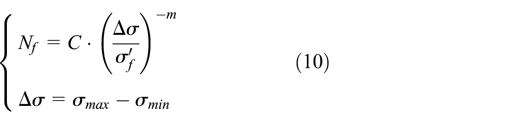
Where,

The steps of fatigue life prediction using Brown-Miller algorithm combined with Morrow average stress correction generally include the following aspects: First, collect material data, such as fatigue strength
Since the material library in Fe-Safe does not include the material 42CrMo for the cardan shaft, the Seeger algorithm is used to estimate the fatigue performance of 42CrMo. The Seeger algorithm generates material S-N fatigue data based on the material’s ultimate tensile strength, elastic modulus, microstructure, surface treatment, environmental conditions, and stress ratio (R-value). Furthermore, the predicted life data from Fe-Safe software can be imported into ABAQUS software in the ODB file format to visually present the simulation results of fatigue life, as shown in Figure 6.

Simulation results of fatigue life for the cardan shaft: (a) fatigue life analysis result of the steel ball, (b) fatigue life analysis result of the universal joint, and (c) fatigue life analysis result of the universal joint housing.
Figure 6(a) is the result of fatigue life analysis of steel ball. It can be seen that the position where the fatigue crack first appeared in the steel ball, and its minimum fatigue life reached the
Optimization design of the cardan shaft
Structural optimization design
Based on the aforementioned simulation analysis results, a novel structure for the cardan shaft was designed. This redesigned cardan shaft utilizes a cycloidal-type torque transmission structure, effectively addressing the failure issues associated with traditional cardan shafts. The optimized structure of the universal joint shaft is shown in Figure 7.
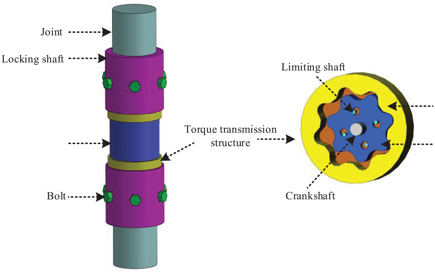
Schematic diagram of the optimized cardan shaft structure.
Figure 7 illustrates the schematic diagram of the optimized cardan shaft structure. This novel cardan shaft consists of a joint, a locking shaft, a connecting rod, and a torque transmission structure, with the torque transmission structure being the core component. The key concept of the torque transmission structure lies in effectively converting the planar planetary motion of the motor rotor into the fixed-axis rotation of the transmission shaft. In this design, the upper joint is connected to the rotor and the crankshaft through splines, enabling the efficient transfer of torque to drive the rotor for eccentric rotation. The rotor is connected to the crankshaft base, thereby driving the crankshaft. The upper end of the crankshaft is connected to the connecting rod with a fixed-axis connection, transmitting the concentric torque to the transmission shaft, thus achieving the conversion from eccentric motion to concentric motion. The maximum eccentric motion amplitude of the rotor is limited by a limiting shaft to ensure the stability of the transmission process. Additionally, the compact design of the internal cycloidal meshing transmission structure compared to other commonly used universal joint shafts significantly reduces the axial dimensions.
Cycloidal design and parameter determination
Let the point on the complex plane correspond to an ordered pair of real numbers (x, y), and let the corresponding complex number be denoted as z, which can be represented as equation (12).

The modulus of complex number z, denoted as r, is given by equation (13).
where Re(z) represents the real part of z, and Im(z) represents the imaginary part of z.
Based on the relationship between the Cartesian coordinate system and the polar coordinate system, combined with Euler’s formula, equation (14) can be derived.

Furthermore, the complex number z can be further transformed into exponential form.


Then the equation for the cycloid is established. The cycloid equation forms the basis for establishing the curve equation of the fixed rotor of the novel cardan shaft. As shown in Figure 8, the auxiliary circle radius is denoted as R1, the rolling circle radius is denoted as R2, the distance between the moving point and the generating point is denoted as d, and the generating point is denoted as M. The period is represented by N = R1/R2 (a natural number), the equivalent moving point 1, and M traces the curve of an N-looped epitrochoid.

Outer cycloidal principle diagram without center method.
Taking the rolling angle θ (0 ≤ θ < 2π) as a parameter, when θ is formed, the center distance vector equation (17) can be obtained based on the complex vector method.

Similarly, the equation (18) for the distance of the moving point can be derived, as well as the equation (19) for the cycloid.


Let

Through the derivation of the above equations, the cycloid equation in the vector coordinate system can be obtained. To transform the vector equation into the Cartesian coordinate system, the Euler’s formula is used. The transformation is shown in equation (22).

In the design of equidistant line type using short-length epitrochoids, the stator’s profile is composed of equidistant curves formed by short-length epitrochoids, while the shape of the rotor evolves into the inner enveloping curve of the stator profile through external rolling. Compared with the standard inner cycloid equidistant line and the short outer cycloid equidistant line, this design shows smoother lines, minimal or no significant buckle phenomenon, and has a smaller eccentricity. The equation of the short inner cycloid equidistant line is derived as shown in (23).

Here, n = N − 1, 0 ≤ θ ≤ 2π, and 0 < K < 1 (K is the amplitude coefficient), which leads to the parametric equations (24) in the Cartesian coordinate system.

For this cardan shaft scheme, taking N = 7 and K = 0.5, a short-length internal epitrochoid, as shown in Figure 9, can be generated.

Short-length internal epitrochoid.
Design and research on stator and rotor of new universal shaft transmission structure
Firstly, the required inner diameter of the universal shaft shell is analyzed, as shown in Figure 10. The inner diameter

Where:
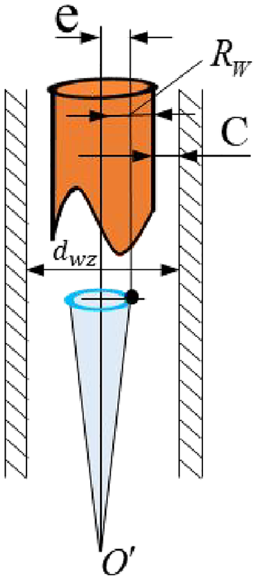
Inner diameter calculation diagram.
At the same time, the maximum swing amount of the rotor under the action of the eccentric torque of the universal shaft should be calculated, which provides a theoretical basis for the design of the eccentric distance of the crank shaft on the universal shaft. In the axial design, the design of the ball hinge is referred to, so the maximum offset along the axial direction has been determined. After the axial offset is determined, the maximum swing amount of the rotation can be calculated, and the maximum offset of the rotor is shown in Figure 11.
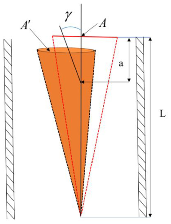
The maximum offset diagram of the rotor.
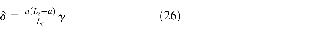
After the original position and the universal shaft are subjected to axial force, the maximum deflection angle
Through the analysis of the meshing line of the stator and rotor of the universal shaft of the screw drill and the calculation of the inner diameter in this section, the two-dimensional structure of the stator and rotor in the torsional structure of the universal shaft can be designed. The two-dimensional diagram of the stator and rotor is shown in Figure 12. In the following figure, the left side is the stator of the universal shaft, and the right side is the rotor of the universal shaft. In order to make the universal shaft have better stability, the head ratio of the stator and rotor of the universal shaft is consistent with that of the motor, which is 8:7.

Two-dimensional drawing of stator and rotor cross-section lines of universal shaft.
Evaluation of optimized cardan shaft design
The optimized cardan shaft design is evaluated using both stress analysis and fatigue life analysis, providing a comparison with the simulation results of the original cardan shaft, highlighting the effectiveness of the optimization.
Stress analysis of the optimized cardan shaft
After importing the optimized cardan shaft model into ABAQUS, the mesh is refined, and the load is applied. One side of the cardan shaft is fixed to simulate the connection with the transmission shaft via threads, while the other side is set with an eccentricity of e = 9 mm to simulate the eccentric motion of the cardan shaft. The total axial force is set to F T = 85.4 kN, and the rotational speed is set to 75 r/min. Fixed constraints are applied on the lower surface of the connecting rod to simulate the threaded connection, and surface-to-surface contact is defined to model the interactions between components. The coefficient of friction between contact surfaces is set to 0.15. The simulation results, as shown in Figure 13, indicate that the maximum stress is located on the rotor, with a stress value of 359.5 MPa. The rotor material, 38CrMoAl, has a yield strength of 833 MPa, and the maximum stress is within the yield limit of the material.

Mises stress contour plots of the optimized cardan shaft: (a) stator stress contour plot, (b) rotor stress contour plot, (c) crankshaft stress contour plot, and (d) limiting shaft stress contour plot.
Figure 13(a) and (d) are the stress nephograms of the stator and the limit shaft respectively. When the meshing occurs, the extrusion causes the stress, and the maximum stress is 216 MPa. Through the Mises stress nephogram of the universal shaft, it is found that the design of the limit shaft makes it inevitable to squeeze the stress when transmitting the eccentric torque, so as to reasonably act on the whole disc of the limit shaft. The four shafts of the limit shaft evenly transfer the stress to the whole disc, which effectively avoids the occurrence of stress concentration, and also effectively reduces the collision between the stator and the rotor during meshing transmission.
Figure 13(b) is the stress cloud diagram of the rotor. It can be seen that the stress generated when the stator and rotor are engaged is more concentrated. This is because the meshing process is affected by the eccentric torque, resulting in a slight swing, resulting in a large meshing stress. However, the stress distribution is relatively uniform, and the maximum stress value is 359.5 MPa. Compared with the previous 805 MPa stress, the stress value is effectively reduced by 55%, which effectively alleviates the problem of stress concentration. Figure 13(c) is the stress cloud diagram of the crank shaft, and the stress is concentrated at the bottom, with a maximum value of 245.1 MPa. The main force of the crank shaft is that the bottom is connected to the rotor and is squeezed, but the eccentric force mainly acts on the limit shaft and the rotor, so the crank shaft is less stressed. At the same time, the force of the upper cylinder is also ideal, which can also reflect that the new universal shaft has certain advantages in transmitting torque and motion.
Through in-depth analysis, it is further recognized that the advantages of this design are not only limited to reducing stress concentration but also extend to its positive impact on the overall structural life and performance. It can effectively distribute the stress generated under eccentric loading, thereby enhancing the durability and reliability of mechanical components. In addition, the implementation of this design helps reduce maintenance costs and extend the equipment’s service life by reducing the likelihood of early damage and fatigue failure caused by stress concentration. Moreover, this structure can significantly free up radial space, providing a new perspective for optimizing and lightweight design of positive displacement motors.
Similarly, the position of the maximum stress value in the new universal shaft transmission structure analyzed in Figure 13 has certain limitations, because the occurrence of the maximum value may be accidental, and it is difficult to describe the overall stress state of the universal shaft. Therefore, the cardan shaft was rotated at 90°, 180°, and 270° using ABAQUS software, and the stress values for these three representative states were exported. Through mathematical statistics, the stress frequency distribution is shown in Figure 14. Compared to the frequency distribution plot of stress in the original cardan shaft, the optimized cardan shaft experiences more uniform loading. During the rotation process, the stress range is concentrated within the range of 100–300 MPa, indicating that the optimized cardan shaft can effectively transmit torque through the meshing structure, thereby maintaining a highly stable transmission process. Additionally, there are no significant stresses that could cause collapse deformation during the transmission, thus enhancing the reliability of the cardan shaft.

Frequency distribution plot of stress in the optimized cardan shaft.
Fatigue life analysis of the optimized cardan shaft
Figure 15 shows the fatigue life analysis results of the stator, rotor, and crank shaft of the optimized universal shaft. These analysis results are based on the stress data of a complete cycle motion under the eccentric torque of the new universal shaft, which is calculated by Fe-Safe software. Figure 15(a) is the analysis result of the fatigue life of the rotor. It can be seen that the position where the fatigue crack first appears in the rotor is the gear of the rotor, and the minimum fatigue life reaches

Fatigue analysis results of the optimized cardan shaft: (a) Rotor fatigue life analysis diagram, (b) Crankshaft fatigue life analysis diagram, and (c) Stator fatigue life analysis diagram.
The optimized torsion structure reduces the stress concentration effect, and the universal shaft shows a significant improvement in fatigue life. The number of cycles it can withstand is as high as 93,325, which is about 82% higher than that of the traditional universal shaft (51,286 cycles). Each cycle represents that the universal shaft starts from a starting position, undergoes a complete rotational motion, and returns to the initial position. In this process, it will be subjected to alternating stress and load. Therefore, the optimized universal shaft can work longer under the same working conditions, thereby improving the reliability of the universal shaft.
Conclusions and discussions
In this study, aiming at the problem of frequent failure of universal shaft of screw drill, the key failure area and failure mechanism of universal shaft are determined by finite element analysis and fatigue life prediction, and a new cycloidal universal shaft is designed by structural optimization. The simulation analysis results fully prove the rationality of the optimized design scheme, which provides a certain reference for the design and application of the new universal shaft. The main research results are as follows:
(1) The maximum stress of the traditional ball hinged universal shaft is mainly concentrated in the lower transition section of the universal joint and the small steel ball, and there is a serious stress concentration problem. Further, the fatigue life analysis was carried out by Fe-Safe software. The results show that the main fatigue failure areas are small steel balls, universal joint grooves, and variable diameter positions. The minimum fatigue life is only 51,286 cycles, which seriously affects the reliability of the universal shaft.
(2) A new type of cycloidal torsion structure universal shaft is optimized and designed. The design can effectively disperse the stress generated under eccentric loading, and the maximum stress value is reduced by 55%, which is within the yield strength of the material. At the same time, the fatigue life of the optimized universal shaft is significantly improved, and it can withstand up to 93,325 cycles, which is about 82% higher than that of the traditional structure, which verifies the effectiveness of the optimization scheme.
The research results of the thesis still have further research. First, when the dynamic model is simulated, the simulated downhole eccentric motion adopts a fixed eccentricity. However, when the screw drill in actual use encounters extreme downhole vibration conditions, the eccentricity in its motion may change slightly. The change is related to the actual working conditions. Therefore, in the follow-up study, a large number of actual working condition data can be collected from the drilling site, and the variation range of the eccentricity can be statistically analyzed, and the dynamic change range is introduced into the simulation model to further improve the accuracy of the simulation results. Second, due to the test conditions and funding constraints, this study did not carry out drilling field test. Therefore, in the future, if there is an actual drilling environment, field tests can be carried out with the help of the actual drilling environment, and the field test results are compared with the simulation results, so as to verify and further correct the model.