
Abstract
Long-term exposure to mechanical vibrations can have detrimental effects on the human body, originating from sources such as vehicles or hand-held power tools. In this study, we examine the transmission of vibrations from a grinding machine to various parts of the hand by integrating two biodynamic models and proposing a new 8-DOF linear model. This new model overcomes the limitations of previous models, allowing for a more efficient investigation of hand vibration transmission. The parameters of vibration transmissibility from the handle to the wrist, forearm, and upper arm were defined and calculated at various elbow angles. The excitation input of the model is a harmonic force generated by a machine in the horizontal direction. The study also investigates the impact of using an isolator and a dynamic vibration absorber (DVA) on hand-transmitted vibration. The isolator is mounted on the handle of the vibrating machine, while the absorber is placed on the forearm. The results indicate a significant reduction in vibration transmission when using the isolator and absorber simultaneously, with a reduction in transmissibility parameters by up to 38.7%. In contrast, using the isolator alone resulted in a reduction of up to 7.9%. The most effective combination was observed at a 180° elbow angle (when the upper arm is horizontally aligned), which was more efficient than other angles. The equations of motion were solved in MATLAB software in the frequency domain, and Adams software was used to validate the model.
Keywords
Introduction
A human body is exposed to different mechanical vibrations in normal daily lives during traveling through vehicles or handling machinery. The human hand is a great organ of versatility capable of grasping and manipulating objects with great dexterity. Hand-transmitted vibration is a phenomenon in which vibration is transmitted to the arm or hand system through the device handle. The biomechanical response of hand-transmitted vibration is very different according to the force and different positions of the hand, which has caused a severe challenge to development in this field. In addition, differences are affected by changes in body shape and laboratory conditions. 1 The study of hand biomechanical models is divided into two general parts. In one case, research on hand vibrations is performed in a laboratory. By installing accelerometer sensors, the amount of vibration in different parts of the hand is measured. In another method, a mathematical model of different parts of the hand is presented. These parts can be lumped parameter or rotating parts. Also, in some cases, the hand model is considered a finite element method (FEM). 2 In 1993, Gurram et al. introduced a 3-DOF model. 3 In 1996, Thomas et al. presented a 5-DOF model. 4 Cherian et al. used a lumped parameter model to study hand vibrations. They studied the effect of energy absorbers on reducing hand-transmitted vibration. In the model used by them, the fingers, wrists, and palms were considered as a set. 5 In 2000, Li et al. examined the effect of hand muscles on the moments of finger joints. Their work provides both an experimental protocol and a biomechanical model that allows estimation of the contribution of the intrinsic and extrinsic muscles to finger joint moments. 6 In 2001, Freund and Takala proposed a dynamic model of the forearm considering fatigue. Their biomechanical model of the forearm consisted of 61 tendons and eight sections. The model can predict the muscle forces in dynamic or static situations when external forces and motion are known. 7 In 2002, Rakheja et al. used driving-point mechanical impedance (DPMI) modulus and phase in different hand models. 8 In 2008, He et al. examined blood flow and finger temperature distribution by presenting a finite element model. 9 Dong et al. developed a 5-DOF model for analyzing the hand-transmitted vibration. In their model, the masses were lumped parameter, and the masses of the palms and fingers were separated. However, in that model, the rotation of different parts was ignored. 10 In 2012, Adewusi et al. introduced a multi-body model for the hand. In 2017, Dong et al. tested vibrations from human hands to the upper arm, shoulder, back, neck, and head in two hand positions. 11 In 2017, Knez et al. introduced a new mathematical model of the finger. He obtained the hand response model for the input vibrations. The results were also obtained through laboratory tests. 12 Marchetti et al. studied the transmission of vibrations to the arm in one direction. The frequency range of the excitation vibrations was from 6 to 500 Hz. The measurement experiment was performed on 34 healthy adults people. 13 In 2018, Dong et al. developed a vibration model of a grinding machine work system. A proposed model was a lumped parameter and vibration transmissibility measured at the wrist and on the upper arm of human subjects. 1 In 2018, Kamalakar and Mitra investigated vibrations using a 5-DOF Dong model. They designed a hand-held isolator that reduced the vibrations of the hand. In the model They examined, the arm had only one degree of freedom in the horizontal direction, and the forearm and wrist were concentrated in one mass. 14 In 2022, Casanova-Batlle et al. investigated influence of an underactuated arm exoskeleton on wrist and elbow kinematics during prioritized activities of daily living. 15 In 2024, Fu et al. presented a direct measurement method for assessing the mechanical impedance and vibration transmissibility of the fingers-hand-arm system during power tool operation in a simulated zero-gravity environment. 16
In this study, we examine the transmission of vibrations to various parts of the hand at different elbow angles by integrating two biodynamic models, the Adewusi et al. 11 and Thomson et al. 4 models, and proposing a new model. The Thomson model previously disregarded finger vibrations, which are considered in this research. The excitation force is applied by a grinding machine that exerts a harmonic force in the horizontal direction onto the hand model. Furthermore, this research investigates the effect of adding an isolator, as used in the Mitra model, along with a dynamic vibration absorber (DVA), on the extent of vibration transmission to different parts of the hand at various elbow angles. The isolator is mounted on the handle of the vibrating machine, while the absorber is placed on the forearm. It is noteworthy that the model is based on the applied excitation force; therefore, the rotation of the upper arm and shoulder joint is not considered in this study, and only the displacement of this joint in the horizontal and vertical directions is taken into account.
Methodology and modeling
Hand-arm modeling
In this study, a linear 8-DOF model of hand-arm was introduced. In this model, the upper arm had a rotary inertia moment to examine the effect of the elbow angle. The arm can vary in the range of angles close to 0°–180° in the presented model. The excitation force is applied by a machine that exerts a harmonic force in the horizontal direction onto the hand model. Figure 1 illustrates the structure of the proposed hand-arm model.

The presented mathematical model of the 8-DOF finger-hand-arm system.
In the presented model, the masses of the fingers and the palm-wrist are represented by mq and mr, respectively. The visco-elastic properties of the tissues are represented by linear stiffness and damping constants, designated as Cq and Kq for the fingers, and Cr and Kr for the palm, respectively. The masses due to the fingers (mf) and the palm wrist (mw) are coupled through linear element Cf and Kf, representing the visco-elastic properties of the carpal and metacarpal bones. A rigid body of mass ma represents the masses of the bones, tissues, and skin of the forearm, and their linear visco-elastic properties are lumped at the wrist Cw and Kw and the elbow Ca and Ka. The masses due to the bone, tissues, and skin of the upper arm are also represented by a rigid body of mass mu, and the linear viscoelastic properties of the upper-arm structure are lumped at the elbow and shoulder (Cu, Cv, Ku, and Kv) joints. Considering that the wrist joint’s rotational movement is neglected, the upper arm is considered to have rotational visco-elastic parameters at the elbow (Ct2 and Kt2) and the shoulder (Ct1 and Kt1) joints. In the model, X0 is the displacement of the handle along the x-axis. The generalized coordinates of the model are chosen as the motions of the masses due to the tissues and skin covering the fingers and the palm-wrist mq, mr (Xq, Xr), fingers mass mf (Xf), palm-wrist mass mw (Xw), forearm mass ma (Xa), the upper arm mass mu (Xu) along the x-axis, the upper-arm mass (Yu) along the y-axis and rotation of the upper-arm mass about its center of mass (θu). L is the upper arm length, and L1 is the distances between the upper arm mass center and elbow joint. In the proposed model, β is the angle between the forearm and the upper arm. The hand and forearm structures are assumed to move along the x-axis, while the upper-arm structure undergoes general plane motion. Usually, the models of hand vibrations are considered linear because of their low vibrations. In this study, the proposed model is linear. The main parameter studied in this study is the vibration transmissibility parameter. Nowadays, this parameter is used in most studies in the field of passenger comfort. Due to this parameter’s dimensionless and independence from input stimulation, it is very efficient to use. In this research, first, the model equations of motion in the time domain are extracted and then transmitted using the Laplace transform to the frequency domain. Then, the presented model defines the vibration transmissibility parameter for the upper arm, forearm, and wrist. After that, the effect of elbow angle on vibration transmission to the wrist, forearm, and upper arm is investigated. Then, by adding the isolator of Kamalakar and Mitra’s model 14 to the proposed model, its effect on vibration transmission is achieved. Finally, by designing dynamic vibration absorbers (DVA) for the forearm, its effect on vibration transmission has been investigated.
Vibration control
Prevent unwanted vibrations in various industries, such as engineers’ concerns. Today, extensive research has been conducted to control and reduce vibrations, both in academic and industrial studies. Research has led to the division of vibration control methods into three general categories:
Vibration damping: In this method, we add vibration damping by adding damping to the primary system and structure.
Vibration isolation: This method is based on the interruption of the vibration propagation path between source and receiver.
Dynamic vibration absorbers (DVA): Another standard method of neutralizing vibrations is to transfer the energy of the primary system to a secondary system, which includes masses and springs and, if necessary, dampers. 17
Adding isolator to the model
Today, different isolators with different properties are provided to reduce transmission vibrations. These materials between the vibrating device and the palm are given in various modeling and experiments. In this study, the effect of vibration transmissibility is obtained by adding an isolator in the Mitra model to the proposed model.
The presented model with the isolating material is shown in Figure 2. Linear stiffness and damping of the isolator are designated as Km1, Cm1, and Km2, Cm2, respectively.

The presented mathematical model with isolator.
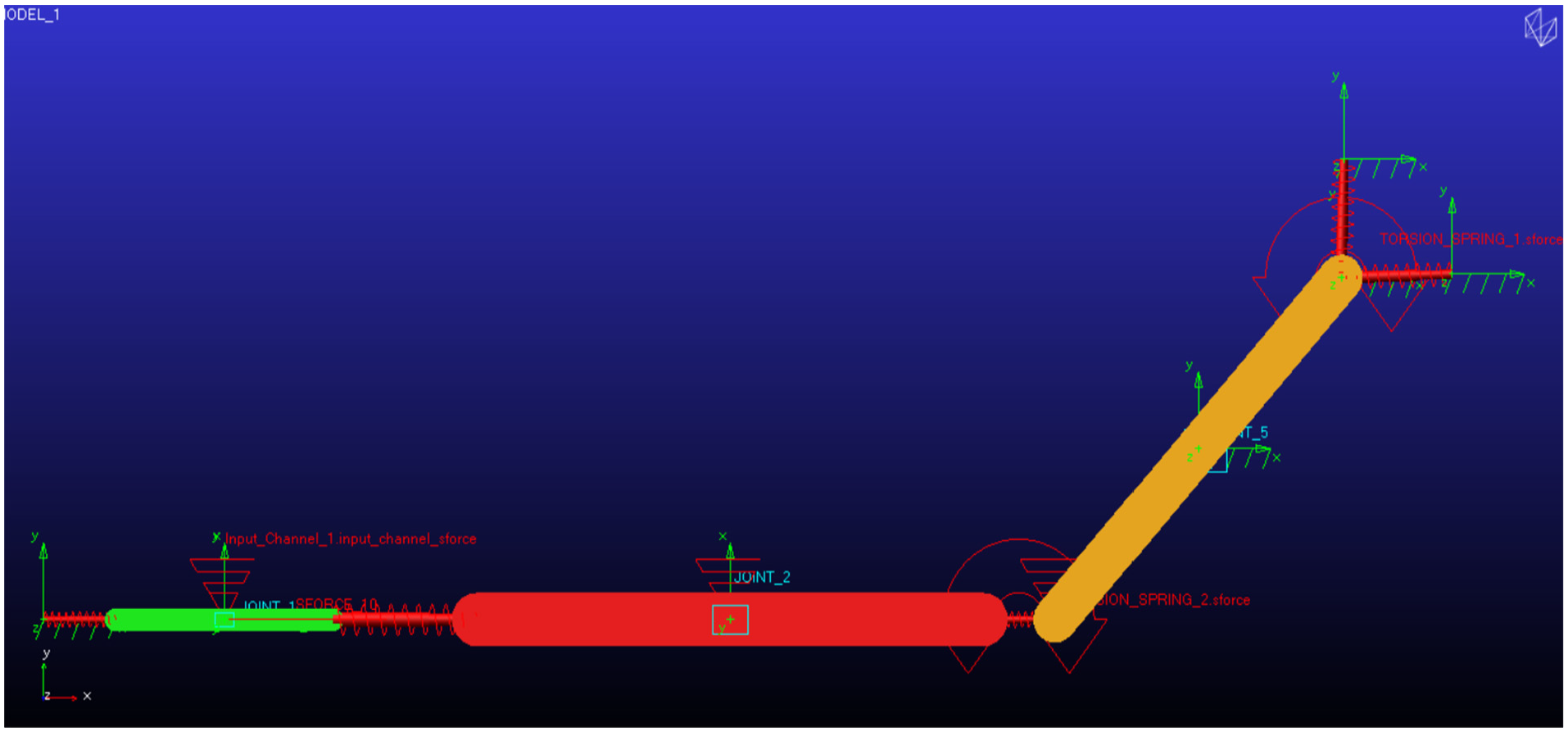
Adding absorber to the model
Dynamic vibration absorbers (DVAs), also called Vibration Neutralizers or Tuned Mass Dampers (TMD), 18 are mechanical appendages comprising inertia, stiffness, and damping elements which, once connected to a given structure or machine, named herein the primary system, are capable of absorbing the vibratory energy at the connection point. As a result, the primary system can be protected from excessively high vibration levels. In practice, DVAs can be included in the original system design or added to an existing system, often as part of a remedial course of action. Since their invention by Frahm at the beginning of the twentieth century, dynamic vibration absorbers have been extensively used to mitigate vibrations in various mechanical systems. A dynamic vibration absorber (DVA) for the forearm was designed and added to the model in this study. The idea comes from a 1996 study by Cherian et al. 5 This absorber, which contains mass, springs, and dampers, reduces the forearm energy transmitted to the upper arm. Figure 3 shows the addition of this absorber to the forearm. The mass, stiffness, and damping coefficient of the absorber are mi, Ki, and Ci. Tables 1 and 2 presents the values of the parameters in the model.

The mathematical model with isolator and dynamic vibration absorber.


Extraction of equations
The equations of motions of the 8-DOF linear model subject to handle excitation x0(t) are expressed in the matrix form as

Where [M] is mass matrix, [C] is damping matrix, [K] is stiffness matrix, {f} is forcing vector, and {x} is vector response coordinates.
Transferring from the time domain to the frequency domain can be performed by Fourier transform. Equation (1) is transmitted from the time domain to the frequency domain. 19 Equation (2) shows the frequency domain.

Where
Handle to Wrist transmissibility (HTW) parameter is defined as a ratio of wrist output response to handle excitation input as equation (3):

Where
Handle to Forearm transmissibility (HTF) parameter is defined as a ratio of Forearm output response to handle excitation input as equation (4):

Where
Handle to Upper arm transmissibility (HTU) parameter is defined as a ratio of upper arm output response to handle excitation input as equation (5) 20 :

Where
Results and discussion
Effect of elbow angle on transmissibility
In this section, first, the effect of the elbow angle on three transmissibility parameters will be examined. Figures 4 to 6 illustrate the effect of different elbow angles on these values. As can be seen in these Figures, the change in the elbow angle has a negligible effect on the wrist transmissibility parameter, but the effect of this angle on the forearm and upper arm transmissibility parameter is significant for the frequencies below 10 Hz.

Handle to wrist transmissibility (HTW) in different angles (deg).

Handle to forearm transmissibility (HTF) in different angles (deg).

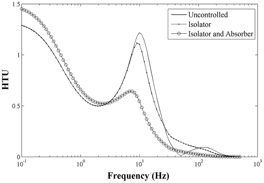
Handle to upper arm transmissibility (HTU) in different angles (deg).
According to the diagrams for frequencies above 10 Hz, the transmissibility parameter of the wrist, forearm, and upper arm are equal at different angles. The difference is for frequencies below 10 Hz. For a better comparison of graphs, the transmissibility parameter for each angle was obtained in the frequency range below 10 Hz. Table 3 shows the results of this study. As can be seen in Table 3, by increasing the angle β (increasing the elbow joint angle) to 90°, the values of the wrist and forearm transmissibility parameters increase and then decrease. The maximum of these parameters occurs at 90° angle of the elbow joint. These values are 1.011 and 0.870 for the wrist and forearm, respectively.
The root mean square of transmissibility parameters in different angles.

As the angle β increases to 135°, the upper arm transmissibility increases and then decreases. The maximum value of this parameter that occurs at 135° is 0.893. The lowest value for these three parameters occurs at 180°. It should be noted that the values given in Table 3 are the root mean square values for frequencies below 10 Hz.
Effect of isolator and absorber on transmissibility
This section investigates the effect of adding isolator and absorber on transmissibility parameters at three angles. Angles have the typical values of 90, 135, and 180. The results of the transmissibility parameters for the uncontrolled model, using isolator and using isolator and absorber simultaneously, are calculated at three angles of the elbow. The isolator attaches to the handle and is in contact with the palms and fingers. The stiffness and damping coefficients of this isolator were extracted from the Mitra study. In the other case, a dynamic vibration absorbent (DVA) is designed for the forearm. Figures 7 to 9 show the results of the transmissibility parameters for the elbow angle.

Handle to wrist transmissibility (HTW) at β = 135°.

Handle to forearm transmissibility (HTF) at β = 135°.
Handle to upper arm transmissibility (HTU) at β = 135°.
Table 4 shows the root mean square values for the three transmissibility parameters at three angles of 90, 135, and 180. The frequency range in which these values are obtained is from 1 to 500 Hz.
The root mean square of transmissibility parameters in different angles without and with absorbers.
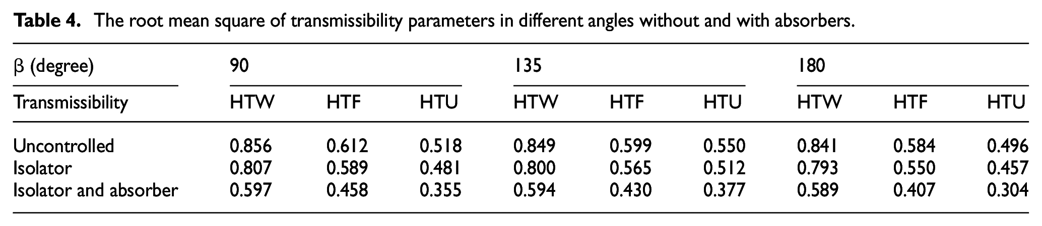
Table 5 shows the percentage reduction of the root mean square of transmissibility parameters in different angles. This table can give us an understanding of the effect of adding isolators and absorber to the model. As the values show, using the isolator and the absorber simultaneous can reduce the transmissibility parameter by up to 38.7%, while using the isolator alone, this value is up to 7.9%. Using the isolator and the absorber simultaneous at 180° of the elbow angle (when the arm is horizontally located) is more efficient than other angles.
Percentage reduction of the root mean square of transmissibility parameters in different angles.

Validation of the model
Model validation was conducted using ADAMS software. In the ADAMS model, similar to the MATLAB model, the grip and push force was assumed to be 30 N. The basic model, both with and without the dynamic vibration absorber (DVA), was simulated using ADAMS software. Figures 10 and 11 display the model images within this software.
Basic hand-arm model without dynamic vibration absorber (DVA).

Basic hand-arm model with dynamic vibration absorber (DVA).
The following presents the validation results of the model incorporating a dynamic vibration absorber in the frequency domain using two software packages. Figure 12 illustrates the gain for various parts of the hand, while Figure 13 depicts the phase for these parts. As evident, the values obtained from MATLAB and ADAMS software are closely aligned, with negligible differences across different hand components.
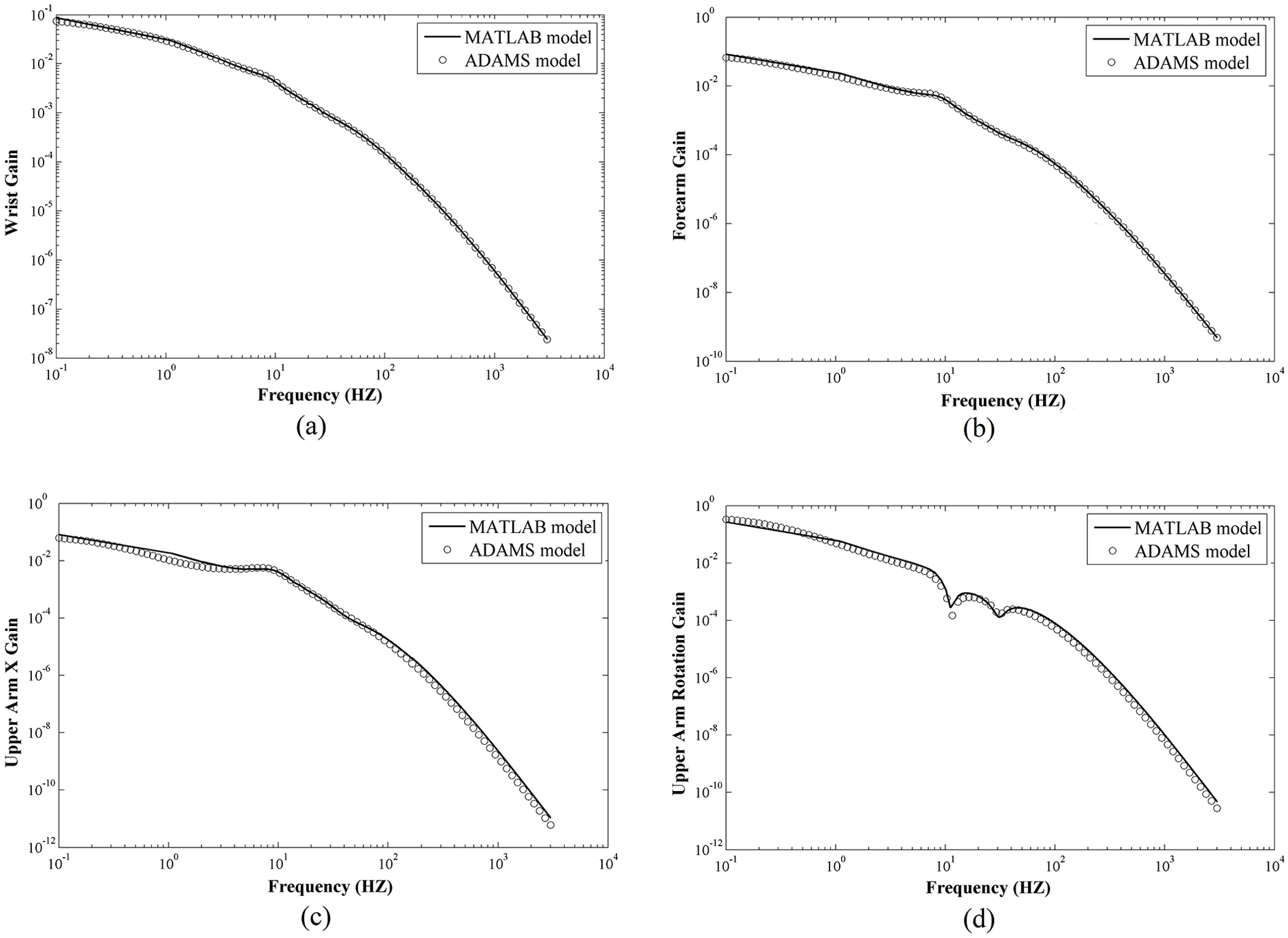
The gain of hand segments in MATLAB and ADAMS software: (a) wrist gain, (b) forearm gain, (c) upper arm × displacement gain, and (d) upper arm rotation gain.

The phase of hand segments in MATLAB and ADAMS software: (a) wrist phase, (b) forearm phase, (c) upper arm × displacement phase, and (d) upper arm rotation phase.
Conclusion
In this study, an eight Degree-of-Freedom (DOF) human hand-arm system model was developed to analyze the vibrations transmissibility of the hand. The proposed model was linear, and the upper arm had a rotary inertia moment to examine the effect of the elbow angle. The change in the elbow angle had a negligible effect on the wrist transmissibility parameter, but the effect on the forearm and upper arm transmissibility parameters was significant for frequencies below 10 Hz. The results showed that for frequencies above 10 Hz, the transmissibility parameters of the wrist, forearm, and upper arm were equal at different angles. The difference was observed for frequencies below 10 Hz, where the maximum values of the wrist and forearm transmissibility parameters occurred at a 90-degree angle of the elbow joint. For the upper arm, the maximum value of transmissibility occurred at a 135° elbow joint angle. The lowest value for these three parameters occurred at 180°. As the values indicated, using an isolator and absorber simultaneously reduced the transmissibility parameter by up to 38.7%, while using the isolator alone reduced it by up to 7.9%. Using the isolator and absorber simultaneously at a 180° elbow angle (when the upper arm is horizontally located) was more efficient than at other angles.
Footnotes
Handling Editor: Sharmili Pandian
Declaration of conflicting interests
The author(s) declared no potential conflicts of interest with respect to the research, authorship, and/or publication of this article.
Funding
The author(s) received no financial support for the research, authorship, and/or publication of this article.