
Abstract
During loading and unloading operations of electric loaders, the traveling system requires frequent starting and braking, a process that has high energy consumption and requires high installed power of the system drive motor. This paper proposes a hydraulic-electric hybrid loader traveling energy-saving system, describes its working principle, designs a hydraulic regenerative braking strategy and an energy-assisted starting strategy, analyzes the braking system in detail, gives a detailed analysis of the braking system, gives how to determine the parameters of the key components such as accumulators and hydraulic motors, and coordinates the powertrain of electric motors and hydraulic pumps/motors. Simulation results show that the scheme can effectively recover and reuse the kinetic energy of the loader during braking, and that it reduces the peak power of the original drive motor by about 19%, and the energy consumption of the whole machine operation by about 30%.
Keywords
Introduction
Environmental problems and the energy crisis have become serious issues shared by the world. In the recent government work reports of many countries, “carbon neutrality” and “peak carbon” have been mentioned many times. Construction machinery belongs to heavy equipment, which has very huge energy consumption due to its large holding capacity and heavy weight. In order to reduce energy consumption, the power source of mobile machinery and equipment is also gradually changing from the original fuel engine to the trend of electrification. Not only that, improving energy recovery and reuse is also an important part. Due to the many applications and high energy consumption of mobile machinery, improving its energy efficiency has become an urgent and challenging task for the industry.1–3 Most traveling mechanical equipment, such as wheel loaders, urban mobile buses, etc., require frequent starting and braking during operation, and a large amount of braking energy will be generated during braking, which will be consumed in the form of friction-generated heat in the form of brake, which will result in a great loss and waste of energy.4–6 Therefore, braking energy recovery and reuse of frequently started and braked traveling machinery and equipment is an effective way to reduce energy consumption.
At present, the main methods of kinetic energy recovery for heavy construction machinery are hydraulic recovery and electric energy recovery.7,8 Hydraulic recovery is to utilize the original hydraulic motor or add a new hydraulic motor to recover the braking kinetic energy in the form of pressure energy through the hydraulic motor into an accumulator, and then use the high-pressure fluid released in the accumulator to sink into the main hydraulic flow system when the equipment needs to be started, so as to assist the drive system. Liu et al. 9 developed a hydrostatic-hydrostatic hybrid power system with the addition of a hydraulic motor and an accumulator circuit, and the system replaces friction braking with hydraulic regenerative braking and recovers hydraulic energy through pump inlet coupling. Test results show that the energy recovery efficiency is more than 50%. Li et al. 10 introduced the structure and working principle of electro-hydraulic hybrid combined with a planetary gear mechanism for electric vehicle drive, and proposed an active energy regulation management strategy that combines drive pattern recognition and fuzzy control, which reduces the energy consumption by about 15% compared with the traditional pure electric drive. Quan et al. 11 proposed an active-passive hybrid drive principle, the system through the hydraulic motor directly to the kinetic and potential energy recovery into the accumulator, greatly reducing the installed power of the construction machinery drive motor. Yu and Ahn 12 in order to improve the efficiency of energy regeneration, proposed a variable hydraulic motor with a combination of control valves and accumulators configurations, through the excavator walking test bed on the energy-saving effect of the test, the test showed that in a variety of different working conditions can be Hao et al. 13 proposed a hybrid hydraulic linear drive principle combining hydraulic cylinders and solenoid valves, in which the solenoid valves are responsible for the motion control of the actuators and the hydraulic cylinders are used for the force control in the hybrid drive system. The results showed that the energy consumption was yet reduced by 58%. Hwang et al. 14 designed a rule-based control strategy for energy allocation management, used a genetic algorithm for global optimization of the system, and obtained the torque variations and the state of charge (SOC) of the battery through the New York City cycle test of the EPANYCC, and the results showed that the power economy of the hydraulic hybrid EV was higher than that of the pure electric vehicle by 36.51%. It can be seen that both hydraulic hybrid and hydraulic electric system architectures have very obvious energy saving advantages over the traditional pure electric drive or pure hydraulic drive modes, but little research has been done on the energy recovery of the system for complex working conditions such as loader traveling operations.
The economy of fuel or energy consumption of construction machinery and equipment also depends mainly on energy control strategies, including energy regeneration braking strategy and reuse assisted starting strategy. Hui and Junqing 15 designed an energy regeneration and reuse strategy based on the logic threshold method to control the dynamic transitions of various operating modes. On this basis, Hui et al. 16 proposed a control strategy combining the logic threshold method and key parameter optimization algorithm to optimize the engine fuel economy and achieve the reduction of installed power. Wen et al. 17 proposed an energy management strategy to dynamically adjust the powertrain mixing degree, and verified the energy-saving test on a loader travel system, and the results showed that the energy consumption was reduced by about 18.9%. Zhou et al. 18 developed a braking control strategy that considers the proportionality between the output torque of the hydraulic pump/motor and its operating pressure, with a focus on meeting the power demand of a medium-sized truck under typical urban driving conditions. Wang et al. 19 proposed a mode-drive control strategy based on the predictability of the loader’s operating modes, and the results showed that the adoption of the mode-drive strategy, the peak power of the battery and motor was reduced by nearly 30%, while the vehicle running time was only slightly increased by 3%. The research results of the above-mentioned scholars and organizations show that the energy saving effect of using the hybrid hydraulic-electric drive principle is very significant and shows great potential in the field of heavy construction machinery and equipment. 20 All of the above research results focus on how to maximize energy recovery, however, there is little research on the strategy of how to re-assist the start-up with the recovered energy.
Based on the above research results, in order to realize the recovery and reuse of braking kinetic energy of the electric loader, and to realize the reduction of installed power and energy saving, this paper proposes a new energy-saving scheme for the travel power system of a hydraulic-electric hybrid loader to capture the kinetic energy lost due to friction braking. The working principle of this system is that the electric motor acts as the main drive when the loader is traveling at a constant speed. When braking is required, the hydraulic motor and accumulator combination recovers the braking kinetic energy. When acceleration is required to start, the accumulator releases pressure energy to drive a hydraulic pump to assist the motor to start. The main innovation of this paper lies in the design of a hydraulic-electric hybrid drive system, and the regenerative braking and energy reuse strategy according to the point of time when the recovered energy is accessed to the system, as well as determining the main parameters of the system components through a large number of simulation tests. The results show that the program effectively improves the energy economy and working performance of the loader travel drive system, and greatly reduces the installed power of the travel drive motor.
Section “Principles of hybrid drive and energy recovery strategies for loaders” describes the hybrid hydraulic-electric principle for loader travel drives. Currently, there is no hybrid hydraulic-electric system model for loader travel drive. This paper proposes a new hybrid drive system accordingly, analyzes the involvement of the motor and pump in the braking process of the system, and designs the braking torque distribution based on the determination of the maximum acceleration threshold. Before the maximum acceleration is reached again, the combination of hydraulic pump and accumulator is utilized to output counter braking torque as much as possible to achieve maximum energy recovery. When the maximum acceleration is exceeded, the motor generates counter braking torque for safety. Meanwhile, in order to maximize the energy utilization, three starting strategies with different capacities are designed and the optimal solution is determined through simulation experiments. The coupling of the hydraulic and electric systems leads to a wide range of parameters, so the determination of the system parameters is very complicated, and this paper determines the parameter selection based on a large number of experimental simulations. In Section “Theoretical analysis and parameter design,” the detailed parameter design process and the precise determination method for the hybrid hydraulic-electric system of the loader are presented. In Section “Simulation studies,” a variety of working conditions simulation experiments are designed to verify the system’s braking energy recovery and emergency braking. In addition, three starting strategies are simulated and verified for comparison, followed by energy recovery and utilization based on the actual operating cycle conditions of the loader. Finally, Section “Conclusion” fully summarizes the contribution of this work.
Principles of hybrid drive and energy recovery strategies for loaders
Material loading and unloading cycle for loaders loader
Figure 1 shows the general work cycle of loading and unloading materials by a motorized wheel loader, which is driven by an electric motor through a gearbox transmission. A complete material loading and unloading operation cycle includes loading material (1–3): the loader travels toward the material to load material, and then backs up with full load. Unloading material (4–6): the loader travels toward the truck with full load, and then backs up with no load after dumping material. In the process of a working cycle, there are two forward movement and backward movement, under the assumption that the loader is the same distance from the material and the truck, the whole process can be divided into a full load of material and forward and backward and empty load forward and backward. The whole process of the loader traveling system needs to be accelerated four times to start and brake. For general electric loader, in braking, in addition to the ground friction resistance generated by part of the braking torque, but also need to provide additional braking torque motor to complete the braking process, this part of the energy if not recycled, and ultimately will be converted into heat dissipation, resulting in energy waste. Therefore, how to cut down the counter braking torque provided by the motor under the premise of ensuring the safety of deceleration and maximize the recovery of braking energy is an important content to be studied in this paper.
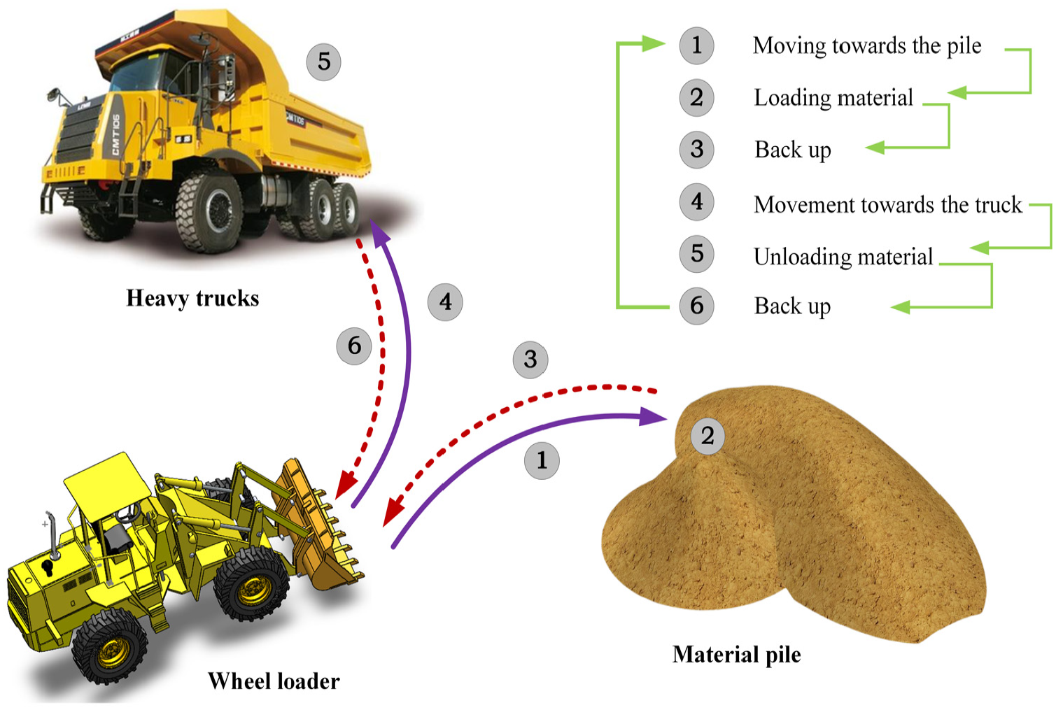
Work cycle of an electric wheel loader.
Hybrid hydraulic electric loader travel drive system principle
The operating principle of the hybrid hydraulic electric loader travel drive system is shown in Figure 2. On top of the original electric drive solution, the system is newly equipped with a hydraulic pump/motor, a hydraulic accumulator, a control valve, a fuel tank, and a relief valve, which together with the hydraulic motor form the travel drive system of the loader. The hydraulic pump/motor is used for the loader in the braking process of kinetic energy and hydraulic energy conversion each other. 2/2 valve is mainly to control whether the hydraulic pump/motor access to the system, when the valve is in the left position, the hydraulic system is not involved in the right position, access to hydraulic pumps and motors. 4/3 valve is in the left position, connecting the accumulator is used for storing the braking energy, and is in the right position, connecting the accumulator releases the braking energy to assist in the drive. The safety valve relief valve is to prevent excessive pressure in the hydraulic system lines and accumulator. Compared with other solutions, the main advantages of this hybrid hydraulic electric drive are higher energy utilization efficiency and drive power performance, and relatively small changes to the hardware configuration of the drive system, which makes it easy to install and use the machine directly.

Principle of operation of the traveling drive system of the hybrid hydraulic electric loader.
When the loader starts to accelerate to start. At this time, the original motor generates driving torque, the 4/3 reversing valve is in the right position fully open state, the 2/2 switching valve is in the right position closed state, the accumulator releases high-pressure fluid to the hydraulic motor, at this time, the hydraulic pump/motor is in the “motor” condition, the driving torque generated through the torque coupler and the torque generated by the motor to drive the loader to generate acceleration, the specific kinetic equations of the system are shown in equation (1).

Where

When the loader needs to stop braking, 4/3 reversing valve is in the left position fully open state, 2/2 switching valve is in the right position, the hydraulic pump/motor outlet is connected to the accumulator, the hydraulic pump/motor is in the “pump” condition, so that the kinetic energy of the rotation is pressed into the accumulator through the hydraulic pump to get the high-pressure oil and thus to recover the braking kinetic energy, and the system kinetic equations are shown in equation (3).

Hydraulic regenerative braking torque distribution
The braking power distribution of a hybrid differs from that of a purely electric drive. To maximize energy recovery, during normal braking, the total braking torque is provided by the hydraulic regenerative braking system, as shown in Figure 3. When emergency braking is required, a composite braking method is used, with braking torque supplied by both the hydraulic regenerative braking and the electric braking to ensure safe and fast to braking. In addition to the friction braking torque, the difference between the maximum regenerative braking torque provided by the hydraulic pump/motor and the required braking torque is provided by the electric braking system. Therefore, the braking torque of the hybrid hydraulic-electric braking system is given in equation (4) as follows.

where

Braking torque distribution.
The weight of the loader varies considerably under different operating conditions between full load and no load, which will result in significant changes in braking energy. Therefore, when selecting the displacement of the hydraulic pump/motor, consideration should be given to the maximum recovery of braking kinetic energy under normal operating conditions at full load.
Energy reuse assisted startup strategies
Hydraulic accumulators have the advantages of high power density, high speed, high frequency of energy charging and discharging, but the energy density is relatively low, so it is necessary to carefully design the energy reuse strategy for its characteristics. In order to maximize the energy-saving potential of the system, three energy-assisted start-up strategies are designed as shown in Figure 4.
Strategy 1: in Stage1 – Motor + Variable hydraulic pump/motor, in Stage 2 – Motor. Stage 1: During the start-up phase, the accumulator provides flow to the hydraulic pump/motor, which outputs drive torque and powers the travel. Stage 2: When the accumulator’s high pressure oil energy has been released and the pressure drops to the minimum operating pressure, the accumulator shuts down, the inlet and outlet of the hydraulic pump/motor discharge are turned on, and the motor alone continues to provide travel power until the end of acceleration.
Strategy 2: in Stage 1 – Motor, in Stage 2 – Motor + Variable hydraulic pump/motor. In Stage 1: At the beginning of the start-up period, travel power is provided by the motor alone. Stage 2: When the loader speed rises to a certain value, the hydraulic pump/motor starts to intervene in the drive system. At this point, the displacement of the hydraulic pump/motor is adjusted to the proper value and torque is coupled to the traveling power system provided by the accumulator and motor to complete the acceleration process.
Strategy 3: in Stage 1, 2 – motor + P/M. The displacement of the hydraulic pump/motor is adjusted to a smaller value throughout the acceleration process from start-up to even speed, with the hydraulic pump/motor and the electric motor jointly providing propulsion power throughout the process.

Energy-assisted startup strategy.
From the intervention point of hydraulic pump and accumulator to recover braking energy can be intuitively analyzed, strategy 1 and 2 will form a shock to the movement of the loader due to the existence of the sudden access and withdrawal of the power system, while strategy 3 is the whole process of auxiliary start, the pressure release is relatively smooth, so the vibration of the loader is relatively small.
Theoretical analysis and parameter design
The theoretical analysis and parameter design of the hydraulic pump/motor and accumulator are carried out according to the parameters of a 6.6 t loader, and the system parameters of the loader are shown in Table 1.
Parameters of a 6.6 t loader.

Hydraulic accumulators
When braking, the hydraulic pump extracts low-pressure hydraulic oil from the tank and delivers it to the accumulator to form high-pressure oil, and the pressure of the gas sealed inside the accumulator will increase, thus storing pressure potential energy. Therefore, the accumulator needs to have enough capacity to store the braking energy of the loader, the calculation is equation (5).
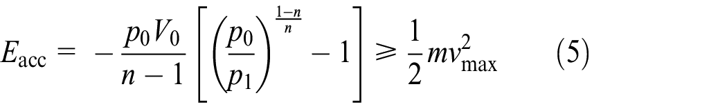
In the formula,
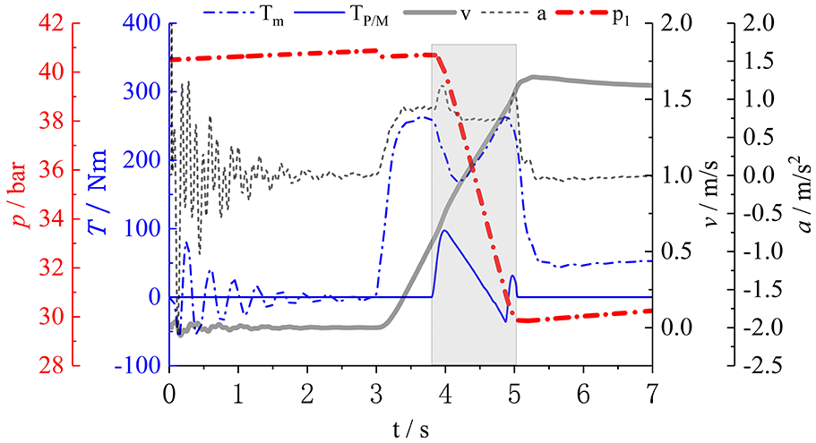
In the hybrid hydraulic electric system, in addition to the fact that a small amount of energy is lost during braking to system friction, piping, hydraulic pumps/motors and valves, in order to convert as much of the braking energy as possible into pressure potential energy in the accumulator, a brake energy is converted into pressure potential energy, it is necessary to set a relatively large initial minimum pressure of the accumulator in order to provide enough braking torque, however, if the torque provided by the accumulator is too large, it will cause a relatively large resistance, but instead, it will make the drive motor to run during braking, resulting in energy consumption. The appropriate accumulator pressure was determined through a large number of simulation experiments, and the results are shown in Figure 5. As can be seen in Figure 5, if the initial pressure of the accumulator is less than 30 bar, the braking torque is insufficient to fully press the kinetic energy into the accumulator, thus requiring the motor to be involved in the braking. After the initial pressure of the accumulator is greater than 30 bar, the braking torque will be too large, forming a resistance to the system, and then the motor increases the driving torque to achieve dynamic balance. Therefore, based on the experimental test method, based on the loader model in this paper, the appropriate pressure of the accumulator is determined to be 30 bar.

Regenerative energy simulation results of braking: (a) loader motion information (speed, acceleration, motor torque, pump pressure, braking torque), (b) hydraulic pump/motor braking torque, (c) motor torque for purely electric drive, and (d) accumulator pressure curve.
The simulation results of the hydraulic regenerative braking energy recovery of the hydraulic-electric hybrid loader traveling drive system under braking with an accumulator initial pressure of 30 bar are shown in Figure 5. The output torque of the hydraulic pump/motor is 130 Nm, and the output torque of the original motor is about 0 Nm. It can be seen that the motor is not involved in braking at this time. During the 3 s when the loader’s traveling speed decreases from 2.3 to 0 m/s, the pressure of the accumulator increases from 30 to 40.5 bar, the hydraulic braking torque also increases, and the braking process of the loader is completed.
The minimum pressure of the accumulator needs to satisfy the conditions by equation (6).

In the formula, the
Hydraulic pumps/motors
The auxiliary power source of the hybrid loader is a variable displacement axial piston pump/motor, which is adjusted by swashplate tilt to absorb or produce the required torque. Therefore, the displacement of the hydraulic pump/motor is determined by the following equation (7).

The displacement of the selected hydraulic pump/motor is 150 mL/r.
Control valves
The 4/3 directional control valve and the 2/2 on/off control valve are both fully open or fully closed during operation; therefore, the minimum flow rate of the valve is determined by the following equation.

The
Simulation studies
A simulation model of the traveling drive system of a hydraulic-electric hybrid loader was built in simulation X environment, as shown in Figure 6, to verify the energy saving effect of the proposed system configuration and energy control strategy. The overall simulation is also carried out to verify the typical working conditions commonly used in loaders. The rolling resistance coefficient between the loader tires and the ground is mainly affected by the type of road surface being driven on, the speed of the vehicle and the specification of the vehicle’s tires. Depending on the operating environment of the loader,
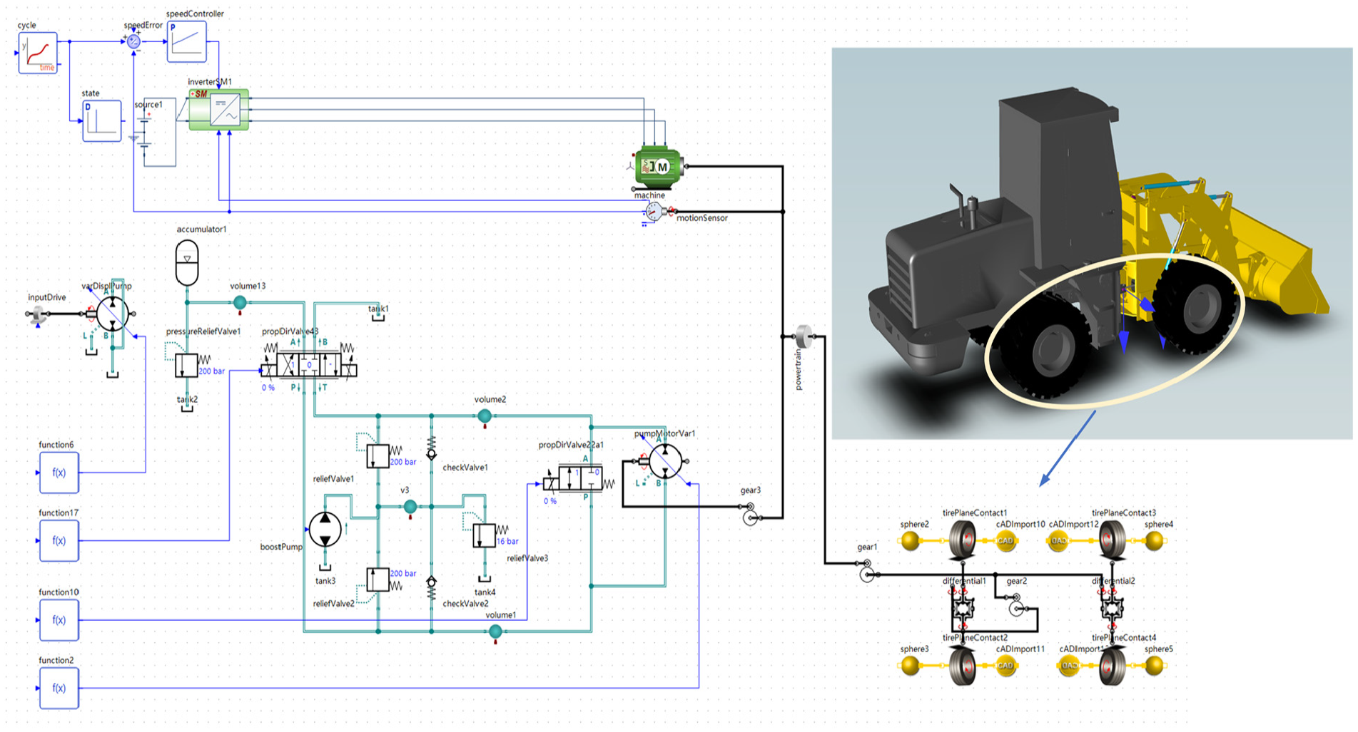
Simulation model of traveling drive system of hybrid hydraulic-electric loader.
Energy reuse assisted starting simulation
The start-up process of the purely electric traveling drive system is shown in Figure 7. The speed of the loader gradually increases from 0 to 1.6 m/s in 2.5 s. In 1–3 s, the loader needs a relatively large start-up acceleration due to the need to overcome the static friction of the system, so the system oscillates strongly. 3–5.5 s, the acceleration process is relatively stable, and the output torque of the electric motor is large, which is about 230 Nm. The acceleration process ends at 5.5 s, when the motor only needs to overcome the ground friction to achieve a uniform motion, and the output torque of the motor drops to about 60 Nm.

Simulation results of the starting process of the loader with purely electric drive.
The simulation process of the assisted starting strategy 1, strategy 2, and strategy 3 designed in this paper are shown in Figures 8 to 10, respectively. The starting torque provided by the accumulator at the intervention time and the intervention time period for different strategies are marked by the shaded areas. In strategy 1, the hydraulic pump/motor provides auxiliary torque at start-up. At this time, the motor is only required to deliver a small amount of torque, approximately 100 Nm. The hydraulic pump/motor provides most of the torque, approximately 130 Nm. Within 3–4.5 s, the pressure in the hydraulic accumulator rapidly drops from 40.5 to 30 bar, and the output torque of the pump/motor also drops. In order to keep the starting acceleration constant, the output torque of the motor is gradually increased. 4.5 s, the accumulator energy is released and the hydraulic pump/motor can no longer provide power. The output torque is 0 Nm and the motor output torque rapidly increases to 230 Nm. Throughout the process it can be seen that the torque of the original motor is small in the first half of the acceleration process and gradually increases in the second half.

Simulation results of strategy 1 assisted startup process.
Simulation results of Strategy 2 assisted startup process.

Simulation results of Strategy 3 assisted startup process.
Strategy 2 is not involved in assisted starting at the beginning of the start-up period, is shown in Figure 9, so the start-up process for 3–3.8 s is the same as for a purely electric drive, about 230 Nm. At 3.7 s, the accumulator releases energy and the output torque of the hydraulic pump/motor assists in the start-up. The hydraulic pump/motor provides part of the drive torque, which is approximately 100 Nm, so that the output torque of the motor is reduced from 230 to 130 Nm. When the accumulator has finished releasing energy, the motor drive torque quickly increases again to 230 Nm, and the whole process releases energy relatively quickly.
Strategy 3 is to assist the entire start-up process, so the displacement of the hydraulic pump/motor needs to be adjusted to achieve a reasonable release of energy from the accumulator to provide torque throughout the process, is shown in Figure 10. In this case, the hydraulic pump/motor provides an output torque of approx. 60 Nm and the motor an output torque of approx. 170 Nm. As the acceleration time increases, the hydraulic pump/motor torque gradually decreases by 30 Nm, the motor drive torque gradually increases to 200 Nm, and the drive is provided by both the hydraulic pump/motor and the electric motor throughout the start-up process. The power source does not suddenly step in and out. Acceleration of the loader is relatively smooth, with the same driving comfort as in a purely electric drive scenario.
The simulation results of motor output power and system energy consumption are shown in Figure 11. At the beginning of startup, most of the Strategy 1 driving torque is provided by the hydraulic pump/motor, so the motor output power is small. The simulation results of motor output power and system energy consumption for the three energy management strategies are shown in Figure 12. At the beginning of startup, most of the drive torque of Strategy 1 is provided by the hydraulic pump/motor, so the motor output power is small. At the end of the accumulator energy release, the loader speed has not yet reached the drive speed, requiring the motor to continue to run at high power, so the peak power of the motor is relatively high in the second half of the drive, which is basically the same as that of the pure electric drive. Strategy 2 is the opposite of Strategy 1. Strategy 2 involves the hydraulic pump/motor assisted drive intervening again after a period of start-up, so the first half of the drive is the same as the purely electric drive scenario, while the second half of the drive greatly reduces the peak power of the motor. Strategy 3 uses fully assisted starting, and due to the slow release of energy from the accumulator, the output power of the motor during the entire drive is between Strategy 1 and Strategy 2.

Power and energy analysis of different auxiliary starting strategies.

Simulation of loading process under no-load condition.
From the point of view of the smoothness of the motor output power, both Strategy 1 and Strategy 2 have more obvious fluctuations at the switching points of the two auxiliary drives (intervention and exit), which is caused by the difference in the dynamic response characteristics of the system, while Strategy 3 has no switching during the whole start-up process, which is much smoother and provides a better driving performance. From the energy consumption point of view, both achieve better energy savings compared to the pure electric drive scheme.
Energy consumption characterization
Setting up the typical operating conditions of the loader as shown in Figure 1, and its cycle period as shown in Figure 12, the simulation comparison of the energy saving capability of the hybrid drive system proposed in this paper, based on the energy management strategy 3, through the pump-valve synergism, the system is shown in Figures 13 and 14 for the comparison of the energy saving capability in the case of no-load and load (1000 kg), respectively. Table 2 statistically shows the results of power and energy consumption comparison with and without load. It can be seen that the peak power of the hydro-electric hybrid is 4.59 kW lower compared to the pure electric at no load, which is about 19.8% lower. The energy consumption of the liquid-electric hybrid is 3.017 × 10⁴ J lower than that of the pure electric power, which is about 32.64%. Under load, the peak power of the liquid-electric hybrid drive is 4.75 kW or about 19.2% lower than that of the pure electric drive. The energy consumption of the liquid-electric hybrid drive is 3.062 × 10⁴ J lower than that of the pure electric drive, which is about 28.88%. Therefore, in a typical whole loader loading and unloading operation work cycle, the liquid-electric hybrid system and energy management strategy proposed in this paper, compared with the original electric-driven loader, the energy consumption of one cycle is reduced by (32.64 + 28.88)/2 = 30.76% on average, and the installed power of the system can be reduced by 19%. This shows that the scheme has better energy saving capability than the purely electric driven loader.

Simulation of loading process under no-load condition: (a) loader position, speed, acceleration, (b) pump and valve control signals, displacement, speed, (c) accumulator pressure, pure electric and hybrid drive torque comparison, and (d) comparison of peak motor power and energy consumption between pure electric and hybrid vehicles.

Simulation of the loading process under load conditions: (a) loader position, speed, acceleration, (b) pump and valve control signals, displacement, speed, (c) accumulator pressure, pure electric and hybrid drive torque comparison, and (d) comparison of peak motor power and energy consumption between pure electric and hybrid vehicles.
Comparison of power and energy consumption between pure electric and hybrid hydraulic electric driving.

Conclusion
The main contribution of this paper is to design an energy efficient solution for the electric drive traveling system of construction machinery or mobile equipment such as loaders, utilizing the configuration of an accumulator and a hydraulic pump/motor combination to capture the braking kinetic energy and redirect it to the auxiliary drive, in order to reduce the installed power of the original drive motor and the system energy consumption. The results of this paper show that under the premise of ensuring safety, hydraulic braking should be used as much as possible to maximize the recovery of braking kinetic energy, and the optimal accumulator initial pressure is determined by observing whether the motor torque is intervening or not. The simulation comparison of the three assisted starting strategies shows that the whole process is smoother when using strategy 3 assisted starting. The scheme proposed in this paper can effectively recover and reuse the braking kinetic energy of the loader during the forward or reverse process, so that the peak power of the drive motor can be reduced by about 19% and the energy consumption of the whole machine can be reduced by about 30%. The scheme is generally applicable to the traveling drive system of general motorized construction machinery. However, the hydraulic-electric hybrid drive system has too many parameters, and the system configuration and optimization is a difficult task. Other energy losses of the system are not considered in this paper, and therefore need to be considered comprehensively subsequently.
Footnotes
Handling Editor: Sharmili Pandian
Declaration of conflicting interests
The author declared no potential conflicts of interest with respect to the research, authorship, and/or publication of this article.
Funding
The author disclosed receipt of the following financial support for the research, authorship, and/or publication of this article: This research was funded by the Shanxi Provincial Natural Science Youth Foundation (202103021223109).