
Abstract
This document describes a mathematical model of an induction motor of vehicles taking into account instantaneous magnetic losses in steel. In order to apply the simulation model in conditions of asymmetry of the supply voltage system and the motor windings, the model is made in a three-phase coordinate system using the method of taking into account the influence of the geometric parameters of the windings on the inductance of the motor. Taking into account instantaneous magnetic losses in steel is performed by introducing variable resistances into the electric circuits of the stator and rotor, which are functions of instantaneous magnetic losses in the steel of the electric motor. The simulation results showed a high convergence of the controlled parameters with the results declared by the manufacturer. This approach to the simulation of an induction motor will allow to use the proposed model in the study of electromechanical processes in the traction drive system, taking into account the peculiarities of the operating modes of electric transport.
Keywords
Introduction
Squirrel-cage induction motors are widely used in transport systems. Thus, induction motors (IM) in electric transport systems are used both as traction electric motors and as drive mechanisms in auxiliary drive systems. Also, induction motors are used as drive mechanisms in marine and river transport, in infrastructure elements of railways, etc. That is why the study of electrodynamic processes occurring in induction motors is an urgent task.
The most complex nature of electrodynamic processes is in induction motors, which are used in the traction drive of electric transport systems. This circumstance is explained by the peculiarities of operation of the traction drive of electric transport. When the nature of the vehicle’s motion changes (acceleration, braking, etc.), transient processes occur in the traction electric drive system, which lead to the emergence of asymmetric modes in the windings of an induction motor.1–3 The appearance of asymmetric modes in the traction drive system of electric vehicles is also affected by such factors as: instability of the supply voltage,4–6 an attempt to stall the motor into skidding.7,8 In addition, the occurrence of asymmetry in the system of traction currents is affected by constant changes in the dynamic load caused by dynamic fluctuations in the cars during the train movement.9–11 The listed modes are not emergency, that is, during simulation, it is not necessary to make changes to the model of the induction motor itself, but when studying the processes in the traction drive system of electric rolling stock, the possibility of the appearance of the specified asymmetric modes should be taken into account.
When simulating systems for diagnosing the presence of emergency asymmetric modes in the traction drive system, caused by damage to the stator,12–14 rotor,15–17 the possibility of changing the induction motor parameters in the model should be taken into account. Also, the simulation model of an induction motor should work correctly in the event of emergency asymmetric modes in the power supply system caused by damage in the valve group of the autonomous voltage inverter.18–20
Operational factors and the possible occurrence of emergency asymmetric modes in the traction drive system determine the factors that form the requirements for the IM simulation model, namely: it should ensure obtaining correct simulation results in case of asymmetry of the IM windings and in case of asymmetry of the supply voltage system.
There are a large number of approaches to simulating an induction motor. Among them, the most common are the models of the induction motor in the two-phase coordinate system, both in the fixed21–23 and in the moving.24–26 Despite their simplicity, the use of such models in the presence of asymmetric regimes of the supply voltage system and motor windings is incorrect. This is explained by the following facts. In IM models, both in stationary and moving coordinate systems, the Clarke transformation is used to convert voltages and currents from a three-phase coordinate system to a two-phase system. The Clarke transformation equations are derived for both symmetric voltage supply systems and symmetric motor winding modes. That is, they do not take into account the zero components of these quantities. Therefore, to study the operation of an IM under voltage supply system asymmetry and asymmetric motor winding modes, some changes should be introduced to the model structure, which will lead to its complexity.
In work, 27 a simulation model of an induction motor in dq coordinates is proposed, which can be studied under winding asymmetry conditions. In this work, it is proposed to perform the transformation of currents and voltages from the abc coordinate system not to dq, but to the dq0 coordinate system. Moreover, in this work, the transformations from the abc coordinate system to dq0 are performed directly, without an intermediate transformation to αβ coordinates. With this approach, components with index 0 will account for the zero components of phase currents and voltages. Since motor winding asymmetry implies that both active resistances and scattering inductances of different stator and rotor phases will be unequal, work 27 presents an algorithm for converting these quantities from the abc coordinate system to dq0.
Analysis of the results presented in work 27 shows that despite an apparently correct approach to modeling an IM with asymmetric windings, it is impossible to account for motor core saturation in such a model. The authors of work 27 themselves point this out. Furthermore, the proposed algorithm for transitioning from the abc coordinate system to dq0, compared to the algorithm of transitioning from the abc coordinate system to dq, leads to an increase in the number of equations with a more complex structure. This complicates the IM simulation model.
In study, 28 a model of an induction motor with a short-circuit fault in one of the motor phases is proposed. The short-circuit fault leads to asymmetric winding modes of the IM. Based on the superposition theorem, the authors hypothesized that the impact of the short-circuit current on torque can be divided into two parts. One is the effect of the absence of phase short-circuit current on the output torque and torque pulsations, and the other is torque pulsations created by the phase short-circuit current. For the phase where a circuit break occurred, a mathematical matrix of reduced winding dimensions is proposed based on the invariant principle of stator magnetomotive force before and after the short-circuit occurrence. Using this matrix, the active resistances and inductances of the stator and rotor windings of the IM are recalculated. The recalculated values of active resistances and scattering inductances are substituted into equations describing the state of electrical circuits of the stator and rotor of the IM. After that, voltage and current transformations are performed from the abc coordinate system to αβ. The disadvantages of this approach to modeling an IM with asymmetric modes are the inability to account for motor core saturation and an increase in the number of equations with a more complex structure.
In works,29,30 models of an induction motor under voltage supply imbalance are proposed. In these works, it is suggested to decompose the three-phase voltage system into positive, negative, and zero sequences, and perform Clarke and Park transformations for each. Then, the motor supply voltages in dq coordinates are determined by the sum of positive, negative, and zero sequence voltage system components in the respective coordinates. In such models, it is impossible to account for motor core saturation. Moreover, the number of equations increases and their structure becomes more complex.
Another class of induction motor models are models built in a three-phase coordinate system.31–33 Despite the fact that these models take into account the possibility of working in conditions of asymmetry both in the windings of the electric motor and in the supply voltage system, these models have a number of disadvantages. One of the shortcomings is the failure to take into account the angle of rotation of the magnetic field when determining the EMFs induced by the rotating magnetic field in the stator and rotor windings, which leads to an incorrect determination of the electromechanical characteristics in conditions of asymmetry of the windings of the electric motor and the supply voltage system. The solution to this problem can be found in works,34–36 where the authors proposed an algorithm for taking into account the angle of rotation of the IM shaft when determining the specified IMFs. However, the application of the methods given in works34–36 when modeling an IM with asymmetric windings is incorrect. This circumstance is connected with the fact that in these works, when determining the values of mutual inductances between the phase windings of the stator and the rotor, the authors used the value of the main inductance of the IM. The analysis of the results given in Goolak et al. 37 shows the correctness of this approach under the conditions of symmetry of the windings, and the incorrectness under the conditions of non-symmetry.
Also, the conditions of asymmetry of the windings open the question regarding the mathematical model of the mechanical part of the IM. The IM torque was determined by vector multiplication of the rotor phase flux linkages and the stator phase currents in many works.38,39 In articles,36,40 the torque is determined by multiplying the corresponding phase currents of the stator and rotor and the mutual inductances between these phases. Moreover, the mutual inductances are functions of the rotation angle of the IM shaft. It can be easily shown that with the symmetry of the windings, the expressions for determining the torque given in studies36,40 will take the form as shown in studies.38,39 The expressions for determining the torque given in works38,39 are incorrect in the conditions of asymmetry of the windings. In Pietrowski and Górny, 40 the authors proposed to take into account the presence of asymmetry in one of the stator windings by decomposing the equations relating to the damaged winding into two components. The equations of the first component are made for the parameters of an undamaged winding, the equations of the second component are for parameters that take into account the degree of damage to the winding. This approach makes it possible to implement a simulation model of an IM with asymmetry of its windings, provided that the asymmetry occurred in one phase of the stator. The structure of the model must be changed if it is necessary to investigate the occurrence of asymmetry in another phase of the stator. The question of the implementation of asymmetry in the rotor windings remains open.
The following conclusions can be the result of the analysis of the existing of IMs models of their suitability for use in conditions of asymmetry of the motor windings, asymmetry and non-sinusoidal of the supply voltage system:
- the mathematical model of an IM must be developed in a three-phase coordinate system;
- the EMFs induced by the rotating magnetic field in the stator and rotor windings, the torque, the mutual inductances between the stator and rotor phase windings should be determined as functions of the angle of rotation of the motor shaft;
- the mutual inductances between the phase windings of the stator and the rotor should be determined as a function of the geometric dimensions of the IM windings.
During the analysis of the works devoted to the modeling of an IM for the study of its operation in the conditions of non-symmetry of the windings, non-symmetry and non-sinusoidal of the supply voltage system, no attention was paid to the consideration of magnetic losses in steel. Magnetic losses in steel are a function of the speed of rotation of the IM shaft.
In works,31–33 it is proposed to take into account the specified losses by including active resistors in each phase of the magnetic circuit of the electric motor. With this approach of taking into account magnetic losses, the design parameters of the electric motor are not taken into account, the function of which is the magnetic losses in the steel of the electric motor.41–43
In work, 41 it is proposed to determine the nonlinearity of electrical steel, non-sinusoidality of the magnetic flux in the gap and current displacement in massive conductors using the finite element method, and in work 42 it is proposed to determine magnetic losses in the steel of an electric motor based on the method of piecewise variable coefficients. Such approaches make it possible to accurately determine the period-averaged magnetic losses in the steel of the electric motor, but do not give an answer about the instantaneous values of magnetic losses, which is important when studying the operation of an induction motor during transient processes. The solution to this problem can be found in the study, 43 where a mathematical model of an induction motor in three-phase coordinates, taking into account instantaneous losses in the motor steel, was developed based on the methodology given in Goolak et al. 44 In the study, 43 instantaneous total magnetic losses are calculated, and they are taken into account when determining the torque of the motor shaft. This approach does not take into account the fact that the inertia of the mechanical part of the electric motor is much greater than the inertia of the processes in the magnetic system of the motor.
This article proposes a simulation model of an induction motor, made in the MATLab/Simulink software environment, made on the basis of its image in the form of a generalized electric machine, taking into account magnetic losses in the steel of the stator and rotor.
The following conclusions are the result of the analysis of studies devoted to the determination and consideration of magnetic losses in steel in the IM simulation model:
- the mathematical model for determining magnetic losses in steel must be developed taking into account the geometric dimensions of the IM windings;
- magnetic losses in steel should be taken into account by changing the parameters of the IM electric circuits.
This document presents the following contributions:
(a) the mathematical model of the IM with a short-circuited rotor is developed on the basis of the provisions of the theory of the generalized electric machine. The model was executed in a three-phase coordinate system in order to investigate the operation of the IM with asymmetry of its windings, asymmetry and non-sinusoidal of the supply voltage system. EMFs induced by the rotating magnetic field in the stator and rotor windings, the torque was determined as a function of the angle of rotation of the IM shaft. Compared to existing models, this made it possible to reduce the number of equations in the mathematical model of the induction motor, and thus simplify its simulation model;
(b) the methodology, which establishes the relationship between the geometric parameters of an IM and its inductance, was applied in the development of a mathematical model. This methodology makes it possible to study its operation in conditions of asymmetry of its windings;
(c) magnetic losses in IM elements are taken into account by introducing variable active resistances into the circuits, which are functions of instantaneous magnetic losses in steel. In existing methods of determining magnetic losses, for example in the equivalent magnetic field method, in contrast to the proposed method, the average magnetic losses over the period are determined in the steel of an induction motor. The application of the proposed method will allow for more accurate investigation of electrodynamic processes in an induction motor using a simulation model;
(d) a simulation model of an IM is developed in the MATLab software environment. The proposed simulation model is implemented in three-phase coordinates. The use of the three-phase coordinate system has the following advantages: the need for additional changes to the simulation model structure when studying the operation of an induction motor under asymmetric winding modes and supply voltage imbalance has been eliminated; it made it possible to take into account the magnetic core saturation by expressing the inductance of the magnetic core as a function of its flux linkage. Accounting for magnetic losses in the simulation model by introducing controlled voltage sources into its electrical circuits made it possible to avoid the model calibration procedure by selecting active resistances in the magnetizing circuits of the induction motor.
(e) A comparison of simulation results obtained from the prototype model 43 and the proposed model was conducted, as a result of which it was established that the results obtained in the stable on the proposed model have somewhat greater convergence with the results declared by the manufacturer.
The simulation results obtained on the prototype model 43 and the proposed model were compared.
This paper is organized as follows: Section “Development of a mathematical model of an induction motor” contains the development of a mathematical model of an IM; a simulation model of an IM is developed in the MATLab software environment in Section “Development of an induction motor simulation model”; a comparison of the simulation results obtained on the prototype model and on the proposed simulation model of the IM is performed in Section “Simulation results”; the discussion of the obtained results is carried out in Section “Discussion”; the document concludes with Section “Conclusions.”
Development of a mathematical model of an induction motor
The object of study
As an object of study, it is proposed to choose a squirrel-cage induction motor of the CTA 1200 series, which is used as a traction motor on alternating current electric locomotives of the DS-3 series (Ukraine). Its parameters are listed in Table 1.32,43
Parameters of the induction motor of the CTA 1200 series.

The results of the calculation of other parameters of an induction motor, necessary for building a simulation model, are given below.
Mathematical model of the electrical part of an induction motor
The physical model of the induction motor looks like the one shown in Figure 1.

Physical model of the induction motor.
In Figure 1, the following notations are used:
us _α, us_β, us_γ– stator phase voltages;
is _α, is_β, is_γ– stator phase currents;
ir _α, ir_β, ir_γ– rotor phase currents;
Rs _α, Rs_β, Rs_γ– active resistances of the stator phases;
Rr _α, Rr_β, Rr_γ– active resistances of the rotor phases;
Ls _α, Ls_β, Ls_γ– total inductances of the stator phases;
Lr _α, Lr_β, Lr_γ– total inductances of the rotor phases;
T– torque on the motor shaft;
ω– angular speed of the motor shaft.
Based on Kirchhoff’s second law and Faraday’s law, for each pair of electrical clamps of an induction motor, the equations of electrical balance in matrix form have the form 45

where
Indices sr mean belonging to the stator winding (s) or rotor (r), and indices αβγ mean belonging to the phase (α), (β), or (γ) of the corresponding winding.
Flux linkage is defined as

The mutual inductances between the stator and rotor windings are functions of the angle of rotation of the IM shaft φ, 46 which is a function of time. Given these facts, the system of equation (1) can be written in the form

The matrices of phase voltages, currents, active phases, and inductances in equation (1) have the form

The voltage

Mathematical model of the mechanical part of an induction motor
The equation of motion of the generalized electric motor is obtained from the Euler-Lagrange equation, taking into account the forces associated with energy dissipation. 47 This is done by applying Rayleigh scattering functions. The system of motion equations is divided into an electrical part (3) and a mechanical part. The mechanical part is the torque on the electric motor shaft and has the form

where J– the moment of inertia of the electric motor shaft;
a– initial speed of the electric motor shaft;
K– initial position of the electric motor shaft.
The last component of equation (6) is the electromagnetic torque, that is,

The torque on its shaft is equal to the electromagnetic torque t in the absence of load on the shaft of the induction motor. Taking into account the fact that in the simulation, the initial position of the IM shaft and its initial angular velocity are assumed to be zero, equation (6) can be rewritten in the form
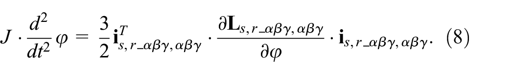
The load on the motor shaft is represented by the static torque Tc. Considering this circumstance, equation (8) can be rewritten in the form

Then the angular speed of rotation of the IM shaft is calculated as

Then the rotation angle of the IM shaft is determined as

Determination of IM inductances
When the windings of the electric motor are damaged, their geometric dimensions change and, as a result, the values of their inductances. The values of the phase inductances as functions of the geometric parameters of the stator and rotor windings were obtained in Goolak et al. 37 An induction motor is a not salient pole electric motor. For a not salient pole electric motor, the value of the stator inductances:

values of rotor inductances:

values of the mutual inductances between the stator and the rotor:

where axial lβ– the length of the air gap;
g = rs−rr– radial value of the air gap;
rs– radius of the stator radius;
rr– rotor radius;
μ– magnetic permeability of vacuum;
p– the number of pairs of poles of an induction motor;
Zs– linear density of the conductor of the current layer of the stator;
Zr– linear density of the conductor of the current layer of the rotor.
The linear density of the conductor of the current layer of the stator was determined as

where ws_αβγ– the number of turns of the corresponding stator winding;
ds– internal diameter of the stator.
The linear density of the conductor of the current layer of the rotor was determined as

zr– the number of rotor rods.
From expressions (10) and (11), the scattering inductances of the corresponding phases are determined. These are inductances that create a scattering flux in the phase. In the matrix

When creating the total magnetic flux in the magnetization circuit, each of the three phases participates, that is, each of the three phases participates in creating the main inductance of the induction motor (inductance of the magnetic circuit). The mutual inductances created by each of the phases are calculated according to the formula

Mutual phase inductance is caused by the creation of a magnetic flux in it by two other phases. Therefore, phase mutual inductances can be calculated by the formula
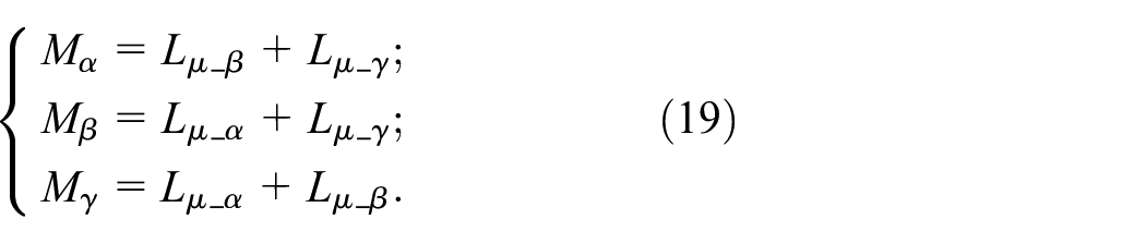
The inductance of the magnetic circuit is the sum of the mutual inductances created by each of the phases

For the symmetrical mode, the values of dissipation inductances of each of the phases of the stator and rotor (17), phase mutual inductances (19), as well as the inductance of the magnetic circuit (20) were calculated. Since for the symmetrical mode of the windings of an induction motor, the dissipation inductances of the stator and rotor, as well as the phase mutual inductances are equal for all three phases, calculations were made only for phase α. Calculation data are listed in Table 2.
The value of inductances of an induction motor.

When calculating the inductances (18), it is possible to take into account the fact that for one winding the mutual inductances are equal to (12) and (13), so they are multiplied by 2. The same applies to the mutual inductances between the stator and the rotor of one phase.
Determination of phase EMFs windings of an induction motor
After substituting equations (12)–(14), (17) into equation (3), it is obtained

where

Determination of magnetic losses in the steel of an induction motor
In work, 43 magnetic losses in steel were taken into account in the form of an increase in the static moment and were transmitted to the magnetic circuits through feedback based on the angular speed of rotation of the motor shaft. The backs of the stator and rotor, the teeth of the stator and rotor are the place of occurrence of magnetic losses in the steel of an induction motor. Taking into account this fact, it is proposed to adjust the method of determining magnetic losses in the steel of the traction electric motor proposed in Goolak et al. 44 When developing a mathematical model of an induction motor, magnetic losses in the steel are proposed to be taken into account in the form of an additional voltage drop in the stator and rotor circuits.
The specific loss equations take into account the accumulation of magnetic energy in the steel. The presented equations can be used for any magnetic material and any geometry for which the material properties and magnetic flux density are known. Specific power losses in electrical steel due to eddy currents and hysteresis taking into account the accumulation of magnetic energy as a function of time at magnetic permeability μr = 1 H/m, material volume V = 1 m3, and material mass m = 1 kg, respectively 39 can be written by the following equation

where Hc– the coercive force, A/(m kg);
Bp– the amplitude of induction, Tl;
ω– the frequency of remagnetization, rad/s;
t– the time, s;
Khyst– the coefficient that takes into account specific hysteresis losses, m/(kg H);
Kaddy– the coefficient that takes into account specific losses due to eddy currents, m/(kg H s);
ploss– the specific power loss, W/(kg m3).
The frequency of remagnetization is found from the expression 39

where p– the number of pairs of poles;
neng– the frequency of rotation of the motor shaft, rps.
The Hc, K hyst , and Kaddy coefficients for electrical steel 2213, which is used in the 2212 series motor, were calculated in Aziz et al., 39 and in this study, it is inappropriate to cite the method of their calculation. Their values were: Hs = 0.00064 A/(kg m), Khyst = 0.018 m/(kg H), and Kaddy = 1.449 × 10⁻⁷ m/(kg H s).
Magnetic losses in an induction motor occur in its structural elements made of electrical steel, namely in the back and teeth of the stator, the back and teeth of the rotor. To determine the implementation of magnetic losses in the steel of an induction motor, in Aziz et al. 39 it is proposed to determine the magnetic induction for each of the structural elements in accordance with the formulas
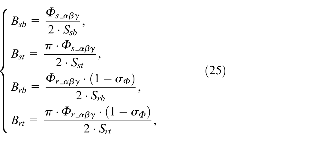
where Ssb, Sst, Srb, Srt– cross-sectional areas of the stator core back, stator teeth, rotor back, rotor teeth, respectively (Table 1);
Φs_αβγ– magnetic flux of the corresponding phase of the stator;
Φr_αβγ– magnetic flux of the corresponding phase of the rotor;
σ Φ – the dispersion coefficient of the magnetic flux (Table 1).
The magnetic fluxes of the respective phases of the stator were determined by the formula

where Is _αβγ– phase currents of the motor stator;
kw = 0.925 – winding factor 43 ;
Ls _αβγ– total inductances of the stator phases of the motor;
ws _αβγ– the number of turns of the stator winding.
Total inductances of the stator and rotor phases of the motor

where Lσs,r_αβγ, αβγ– dissipation inductances of the stator and rotor phases of the electric motor;
Mαβγ– mutual inductances of the electric motor phases.
The magnetic fluxes of the corresponding phases of the rotor were determined in accordance with the formula

where Ir _αβγ– phase currents of the rotor of the motor;
kw = 0.925 – winding factor 43 ;
Lr_αβγ– total inductances of the rotor phases of the motor;
zr_αβγ– the number of teeth of the rotor winding.
When moving from specific magnetic losses in the steel of an induction motor to total losses, the masses and volumes of structural elements should be taken into account.
Coefficients Hc, Khyst, and Kaddy in work 43 were determined for specific power losses expressed in W/(kg m3). To get to the losses expressed in W, equation (24) is multiplied by the steel mass of the corresponding structural element of the electric motor and its volume. The volume of the structural element is determined by the expression

where mi– steel mass of the structural element, kg (Table 1);
ρ = 7750 kg/m3– specific gravity of electrical steel 2213.
Instantaneous values of magnetic losses in the structural elements of an induction motor, taking into account the above, have the form

where ploss_i(t) – specific instantaneous magnetic loss in the i-th structural element of the induction motor.
Therefore, the total instantaneous magnetic losses in the steel of the stator and the steel of the rotor of an induction motor is the sum of the specific magnetic losses in its structural elements, namely in the back and teeth of the stator, the back and teeth of the rotor. 39 That is,
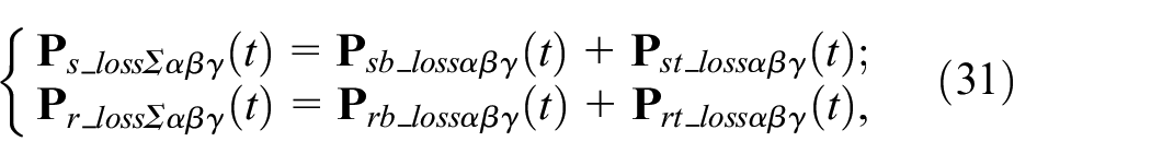
where
During the development of the simulation model for instantaneous magnetic losses in steel, the following considerations were taken into account. Magnetic losses in steel lead to a reduction in the excitation current of the induction motor. This circumstance results in decreased phase currents of the stator and rotor. In the equivalent circuit of the induction motor, the stator winding, rotor winding, and magnetic core are connected in parallel. Therefore, in many inductions motor models, the active resistance is connected in parallel to the excitation circuit to account for magnetic losses in the steel. In these models, an approximate value of active resistance is used. Subsequently, the obtained result is adjusted to obtain phase current values of the stator in a stable regime, equal to the manufacturer’s specified values. Such an approach does not consider the change in magnetic losses in steel over time, which has a trigonometric dependence on the rotor angle. Therefore, magnetic losses should be accounted for by introducing variable resistance into the magnetic core of the induction motor rather than constant resistance. The magnetic coupling between the stator and rotor windings in the proposed induction motor model is accounted for using phase EMFs, thus eliminating the explicit representation of the magnetic core. It is suggested to transfer the variable resistance of the magnetic core to the stator and rotor phase circuits.
Then, the voltage drops in the phase windings of the stator and rotor, used to model magnetic losses in steel, can be determined as follows

Taking into account equation (32), expression (22) is shown in the following form
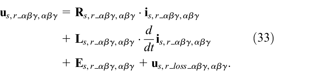
Equation (33) is a mathematical model of the electrical part of an induction motor.
Considering the saturation of the magnetic circuit of the induction motor
An important factor affecting the dynamic characteristics of an induction motor is the saturation of its magnetic circuit.32,45,49 Work 32 shows that the approach based on the use of nonlinear coefficients, unlike the approach based on taking into account the harmonic composition of voltages and currents, does not require a priori knowledge of the quantitative characteristics of the harmonic composition of the specified quantities. In studies,32,48,49 it is proposed to take into account the saturation of each phase of an induction motor by using the dependence of the main inductance as a function of the amplitude of the spatial flux vector of the magnetizing circuit, that is, Lμ = f(ψμΣm).
The total flux linkage ψμΣm is obtained from the expression

where ψμx and ψμy– amplitudes of the projections of the space vector of the flux linkage of the magnetic circuit onto the orthogonal axes of the X and Y coordinates.
Since the mathematical model of an induction motor is made in three-phase coordinates, in order to determine the projections of the flux linkage of the magnetic circuit on the X and Y coordinate axes, the transition to the αβ coordinate system is first performed50–52

where Ψμ_α, Ψμ_β, Ψμ_γ– phase flux linkages of the magnetic circuit.
Then the transformation from the αβ coordinate system to the xy coordinate system was performed53–55

where φ– the electrical angle of rotation of the induction motor shaft;
p– the number of pairs of poles.
The phase flux linkages of the magnetic circuit were determined based on the following considerations. The voltage applied to the stator winding equals the sum of voltage drops across the winding’s active resistance, the voltage generated by the flux linkage, and the voltage across the magnetic circuit clamps.56–58 Taking this into account and substituting the expression for determining the total phase inductance (36) into the first three equations of the system (1) and after corresponding transformations considering the voltage drops caused by magnetic losses in the steel, we obtained

Expressions for finding the derivatives of the phase flux linkage of the magnetic circuit of the induction motor were derived from the system of equation (33)

The values of the phase flux linkages of the magnetic circuit of the induction motor can be easily obtained from the system of equation (38).
For the convenience of simulating the flux linkage of the magnetic circuit and the main inductance are depicted in relative units. The main inductance of an induction motor in relative units has the form

where Lμ– the instantaneous value of the total inductance of the stator winding phase;
Lμ_nom– the nominal value of the total inductance of the stator winding phase.
The instantaneous value of the main flux linkage 32

where |ψμΣ| – the modulus of the instantaneous value of the main flux linkage;
ψμΣnom– nominal value of the main flux linkage.
The dependence of the value of the main inductance on the instantaneous value of the flux linkage of the magnetic flux IM in relative units is shown in Figure 2.
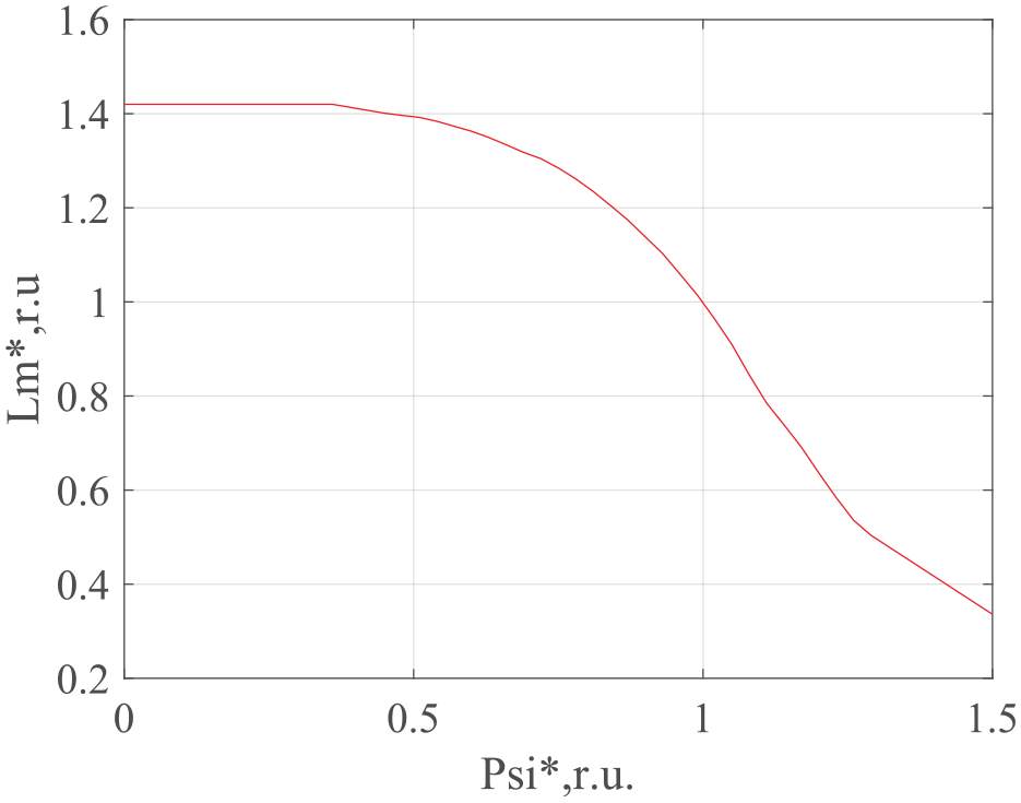
Main inductance as a function of the flux linkage of the magnetic circuit of the induction motor in relative units.
On the simulation model, all inductances are multiplied by the value of the main inductance of the induction motor, expressed in relative units.
Development of an induction motor simulation model
The structure of the induction motor simulation model consists of the following elements:
Implementation of the mathematical model of the electrical component;
Implementation of the mathematical model of the mechanical component;
Consideration of magnetic losses in the steel;
Visualization of the obtained results.
Development of the simulation model for the electrical component of the induction motor
The mathematical model of the electrical part of the IM is described by the system of equation (3). The constituent elements of the electrical part of the mathematical model are the following parameters of an IM: phase active resistances and dispersion inductances of the stator and rotor and the main inductance of the magnetic circuit. Moreover, the IM parameters must be able to change. This refers to the organization of asymmetric winding modes of an IM. Works31,32,43 show the effectiveness of the implementation in the MATLab software environment of the Simscape/Specialized Power Systems library of winding models for studying the IM operation in conditions of their asymmetry. Therefore, in the proposed simulation model, the IM windings are implemented on the elements of the MATLab/Simscape/Specialized Power Systems library. The system of supply voltages of an IM is also implemented in this library. All other elements of the simulation model are implemented in the MATLab/Simulink library.
When creating a simulation model of an IM, the following parameters are used:
- active resistances of the stator and rotor phases Rs,r_αβγ,αβγ, the values of which are given in Table 1. The active resistances of the stator and rotor phases are set in the form of parameters of the “Resistance” elements;
- phase inductances of stator and rotor dissipation Lσs,r_αβγ,αβγ (Table 1). They are set in the form of “Inductance” element parameters.
Also, when creating a simulation model, the geometric parameters and structural parameters of the IM (Table 1) are used, which are combined in the “Parameter block of the IM.” The asymmetric mode of the IM windings is set by changing the required parameter in the “Parameter block of the IM” and by changing the Rs,r_αβγ,αβγ and Lσs,r_αβγ,αβγ parameters of the corresponding phase. “Parameter block of the IM” is implemented in MATLab/Simulink in the form of constants. Therefore, its internal structure is not given.
The implementation of the mathematical model of the electrical part of the induction motor (3) is shown on the example of simulation models of the stator (Figure 3) and rotor (Figure 4) windings of phase a. In the simulation models, the indices α, β, and γ, which mean the parameter belongs to the corresponding phase, are replaced by a, b, and c, respectively. The specified replacements also apply to all models listed below.

Simulation model of the phase a stator winding of an IM.

Simulation model of the rotor winding of phase a of an IM.
For convenience, the simulation models of the stator windings (Figure 3) of all three phases are combined in the “Stator phase current determination unit” (Figure 5(a)). The rotor windings (Figure 4) of all three phases are combined in the “Rotor phase current determination unit” (Figure 5(b)). In Figure 5 outputs A1, X1 correspond to the beginning and end of the stator winding of phase a, outputs A2, X2 to the beginning and end of the rotor winding of phase a, B1, Y1 to the beginning and end of the stator winding of phase b, outputs B2, Y2 correspond to the beginning and end of the rotor winding of phase b, C1, Z1 of the beginning and end of the stator winding of phase s, output C2, Z2 of the beginning and end of the rotor winding of phase c.
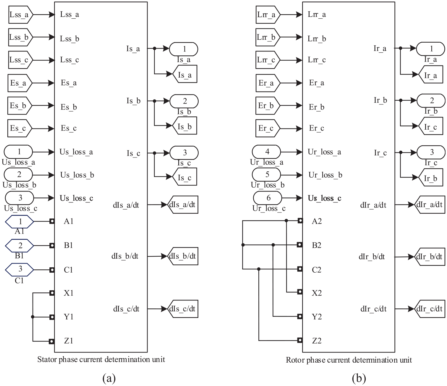
Simulation model “Unit of definition of phase currents of an induction motor”: (a) “Stator phase current determination unit” and (b) “Rotor phase current determination unit.”
“EMF calculation unit” serves to implement equation (5). It calculates the phase EMFs of the stator and rotor, which arise as a result of mechanical motion. The specified phase EMFs are related to the conversion of electrical energy and express the interaction of the electrical and mechanical systems of an IM. Equation (5) are implemented in the form of m-files of MATLab functions. Moreover, in one m-file of MATLab functions, the phase EMF of one phase of the stator or rotor is calculated. The MATLab function for calculating the stator EMF of phase a is shown in Figure 6(a). Determination of mutual inductances between the stator and rotor (14) and phase inductances of dispersion (17) is carried out in “Unit for calculation of inductances.”Equations (14)–(17) are implemented in it. One block of m-file MATLab function is used to calculate each inductance. An example of the MATLab function for calculating the mutual inductance between the stator and the rotor of phase a is shown in Figure 6(b). The calculated values of the inductance are multiplied by the Lμ* signal coming from the “Unit for taking into account the saturation of the magnetic circuit of an IM” to take into account the saturation of the magnetic circuit of the IM.
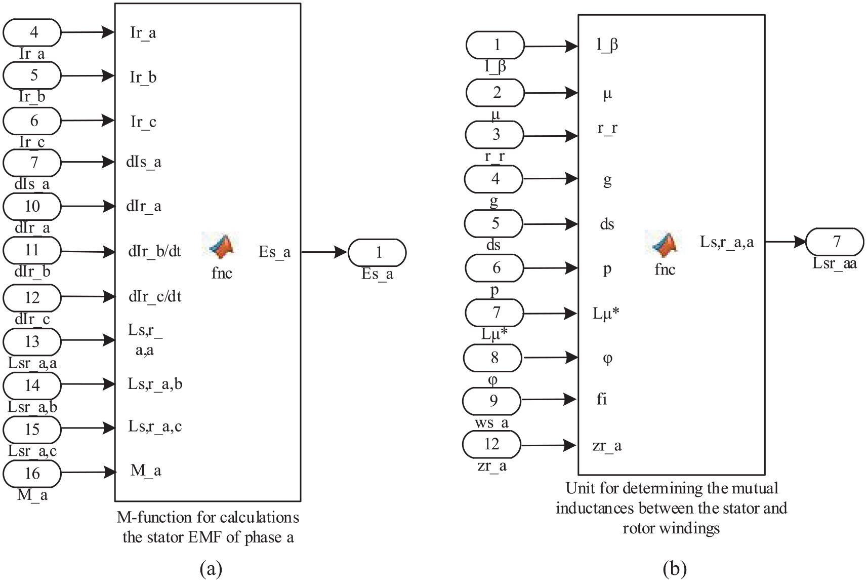
MATLab functions: calculating the EMF of the stator phase a (a) and calculation of the mutual inductance between the stator and the rotor of phase a (b).
The derivatives of phase flux linkages of the magnetic circuit of the IM are calculated in the “Unit for taking into account the saturation of the magnetic circuit of an IM” using equation (38). The implementation of the calculations of the derivatives of phase flux linkages of the magnetic circuit is done in the form of MATLAB function m-files. An example of the MATLAB function for calculating the flux linkages of phase a of the magnetic circuit is shown in Figure 7. After integrating the derivatives of the flux linkages of the magnetic circuit, the obtained values of flux linkages are transformed from the three-phase coordinate system to the αβ coordinate system using the “abc to Alpha-Beta-Zero” element of the MATLAB/Simscape library. Subsequently, the obtained values in the αβ coordinate system are transformed into dq coordinates using the “Alpha-Beta-Zero to dq0” element of the MATLAB/Simscape library (Figure 8). The magnitude of the flux linkage vector of the magnetic circuit (34) and the instantaneous value of the flux linkage vector of the magnetic circuit in relative units (38) are calculated using MATLAB function m-files (Figure 8). The dependence of inductance on the instantaneous value of the flux linkage of the magnetic circuit is represented as a 1-D Lookup Table in MATLAB/Simulink/Lookup Table.

MATLab function for calculating the flux linkage of the magnetic circuit of phase a.

Simulation model for determining the dependence of the inductance on the instantaneous value of the flux linkage of the magnetic circuit.
“Parameter block of the IM,”“Unit of definition of phase currents of an induction motor,”“Rotor phase current determination unit,”“EMF calculation unit,”“Unit for calculation of inductances,” and “Unit for taking into account the saturation of the magnetic circuit of an IM” are combined into “The unit for calculating the electrical parameters of the IM.”
Development of a simulation model of the mechanical part of an induction motor
The simulation model of the mechanical part of the IM implements equations (9)–(11) of its mathematical model. All elements of calculating the mechanical parameters of an IM are summarized in the “Unit for calculating the mechanical parameters of an IM” (Figure 9). The dynamic torque (the difference between the electromagnetic and static torques) is calculated using the m-file of the MATLab function. The angular acceleration of the IM shaft is determined by dividing the dynamic torque by the moment of inertia J. The angular speed of rotation ω is obtained after integration of the angular acceleration, and the angle of rotation of the shaft φ is obtained after repeated integration. The frequency of rotation of the IM shaft is determined in “Unit for calculating the mechanical parameters of an IM” in accordance with the equation


“Unit for calculating the mechanical parameters of an IM” simulation model.
Development of a simulation model for determining magnetic losses in steel
The calculation of voltage drops in the windings of the stator and rotor, caused by magnetic losses in the steel, is performed in the “Unit for calculating voltage drops due to magnetic losses in IM steel.” This unit comprises the “Unit of mass and dimensional parameters of windings of an IM” (Figure 10(a)) and the “Unit for calculating the voltage drop in the stator winding of phase a of an IM caused by magnetic losses in steel” (Figure 10(b)). In the “Unit for calculating the voltage drop in the stator winding of phases of an IM caused by magnetic losses in steel,” equations (23)–(31) are implemented using MATLAB function m-files. The calculation of voltage drops caused by magnetic losses in the steel is carried out separately for each phase of the stator and rotor. An example of the calculation of voltage drop due to magnetic losses in steel for phase a of the IM stator is shown in Figure 10(b).

“Unit of mass and dimensional parameters of IM windings” (a) and unit for calculating the voltage drop in the stator winding of phase a of an IM caused by magnetic losses in steel (b).
Development of a comprehensive simulation model of an induction motor
As mentioned earlier, the electrical part of the IM is represented by the “Unit for calculating the electrical parameters of the IM,” while the mechanical part is represented by the “Unit for calculating the mechanical parameters of the IM.” Calculation of voltage drops in the phases of the IM is carried out in the “Unit for calculating voltage drops caused by magnetic losses in steel of an IM.” The power supply system is implemented using three elements of the alternating current voltage source library MATLab/Simscape/Specialized Power Systems. Scope elements of the MATLab/Simulink library are used to display the simulation results. Since elements of the MATLab/Simscape library are used in creating the simulation model, the “powergui” element with the continuity parameter is used to select continuous calculation mode. The comprehensive simulation model of the IM is shown in Figure 11.

Comprehensive simulation model of an induction motor.
On the comprehensive simulation model (Figure 11), the following parameters can be monitored: shaft rotation frequency of the IM (Scope n), torque (Scope T), phase stator currents (Scope Is_a, Ia_b, Is_c). If it is necessary to monitor other parameters, it is possible to create appropriate outputs from the blocks where they are defined and connect them to Scope.
Simulation results
The effectiveness of the proposed solutions in the development of a mathematical model of an IM was performed as follows.
The simulation model of an IM presented in the study 43 was chosen as the prototype model. On the proposed simulation model and the simulation model, the prototype, the starting characteristics of the phase currents of the stator, the torque, and the frequency of rotation of the shaft of an induction motor were obtained for the following conditions:
Nominal operating mode of an IM with symmetrical windings without taking into account magnetic losses in steel.
Nominal operating mode of an IM with asymmetric windings without taking into account magnetic losses in steel.
Nominal operating mode of an IM with symmetrical windings taking into account magnetic losses in steel.
Nominal operating mode of an IM with asymmetric windings taking into account magnetic losses in steel.
The following parameters were determined for the stable mode of IM operation: the instantaneous value of the phase voltages of the stator currents, the torque, and the frequency of rotation of the shaft. The specified parameters obtained in the simulation results for the third mode were compared with the data declared by the manufacturer (Table 1).
Simulation results for symmetrical windings of an IM without taking into account magnetic losses in steel
The following characteristics were obtained for the nominal mode of IM operation with symmetrical windings without taking into account magnetic losses in steel (experiment 1) on the prototype model and the proposed model:
- phase current diagrams for the prototype model (Figure 12(a)) and for the proposed model (Figure 12(b));
- diagrams of phase currents in stable mode for the prototype model (Figure 13(a)) and for the proposed model (Figure 13(b));
- torque diagrams for the prototype model (Figure 14(a)) and for the proposed model (Figure 14(b));
- diagrams of the rotation frequency of the IM shaft for the prototype model (Figure 15(a)) and for the proposed model (Figure 15(b)).

Diagrams of phase currents for the prototype model (a) and for the proposed model (b), obtained for the nominal operating mode of the IM with symmetrical windings without taking into account magnetic losses in steel.
Diagrams of phase currents in a stable mode for the prototype model (a) and for the proposed model (b), obtained for the nominal operating mode of the IM with symmetrical windings without taking into account magnetic losses in steel.

Torque diagrams for the prototype model (a) and for the proposed model (b), obtained for the nominal operating mode of the IM with symmetrical windings without taking into account magnetic losses in steel.
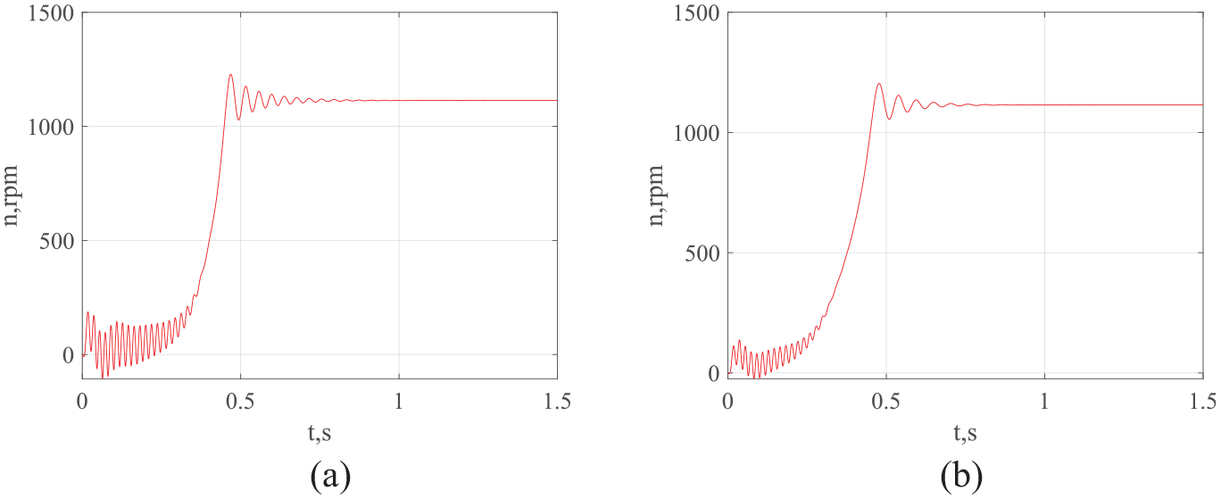
Diagrams of the frequency of rotation of the IM shaft for the prototype model (a) and for the proposed model (b), obtained for the nominal operating mode of the IM with symmetrical windings without taking into account magnetic losses in steel.
For a stable mode, the instantaneous values of the stator phase current, torque, and rotation frequency of the IM shaft are obtained. The results are listed in Table 3.
Simulation results.

Simulation results for asymmetric IM windings without taking into account magnetic losses in steel
The following characteristics were obtained for the nominal mode of IM operation with asymmetrical windings without taking into account magnetic losses in steel (experiment 2) on the prototype model and the proposed model:
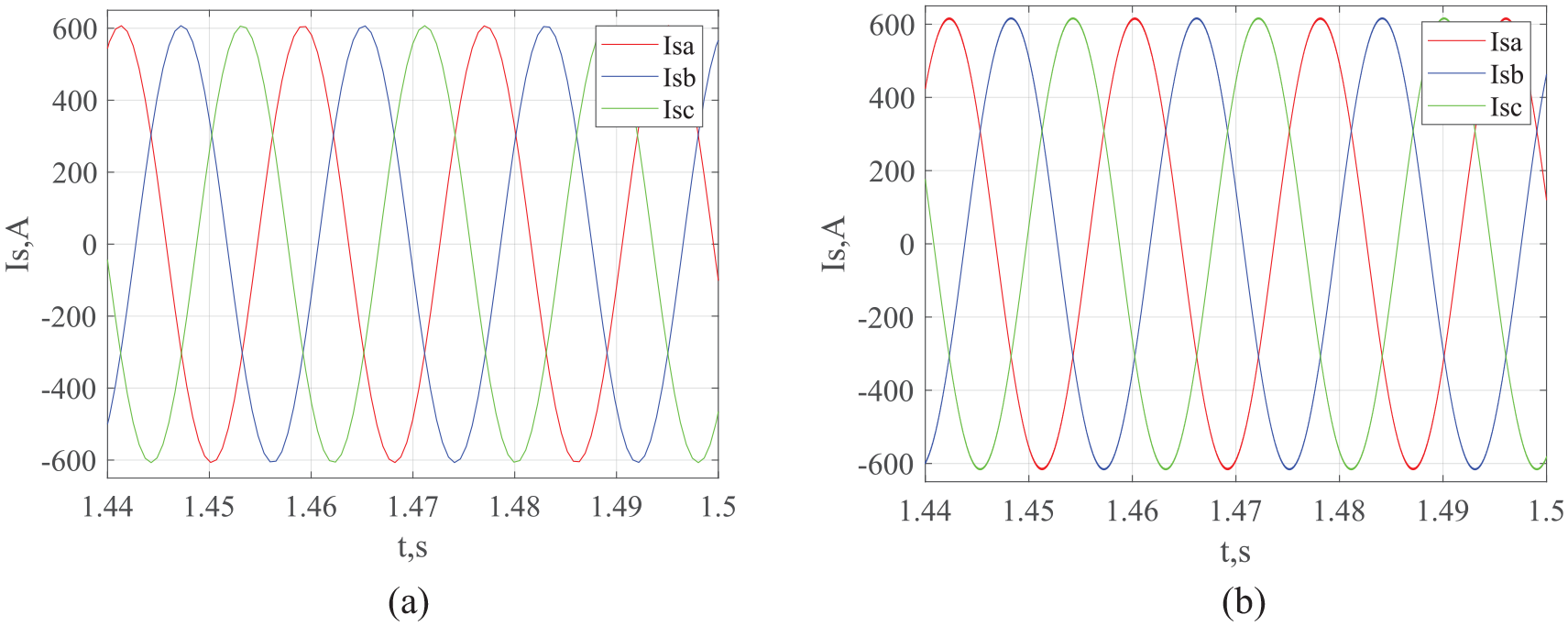
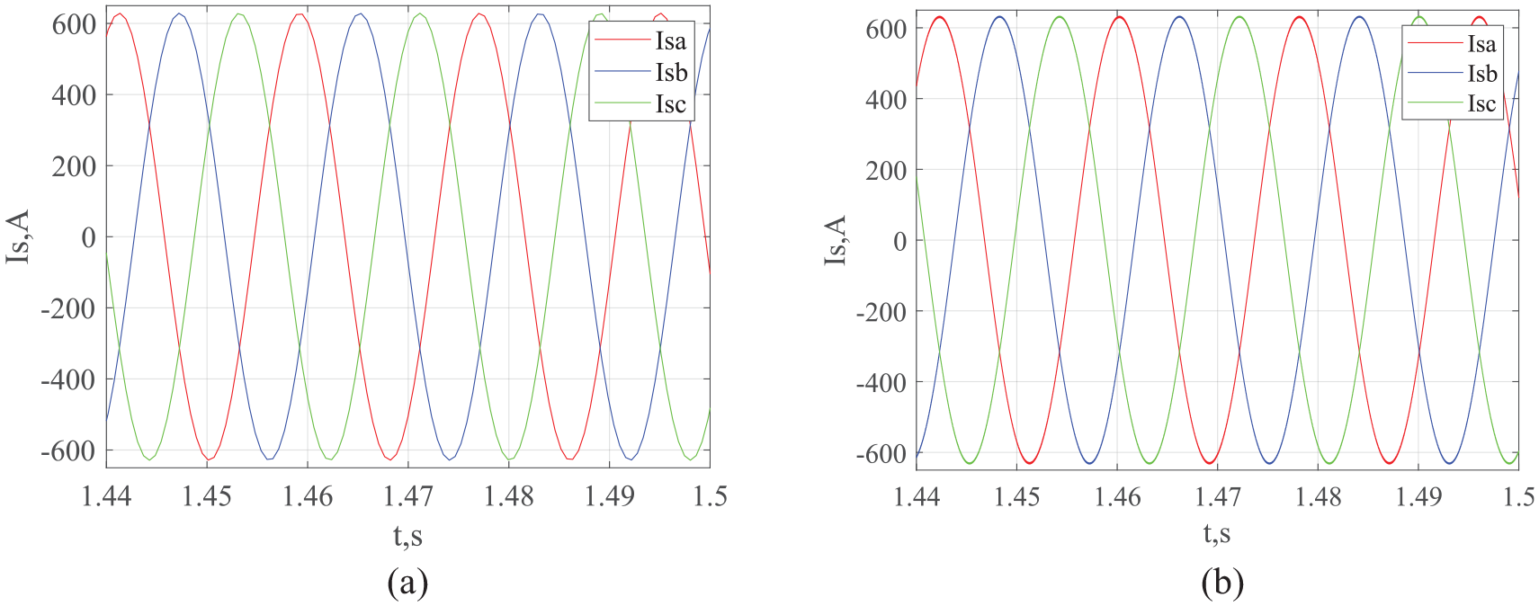
- diagrams of phase currents in stable mode for the prototype model (Figure 16(a)) and for the proposed model (Figure 16(b));
- torque diagrams in stable mode for the prototype model (Figure 17(a)) and for the proposed model (Figure 17(b));
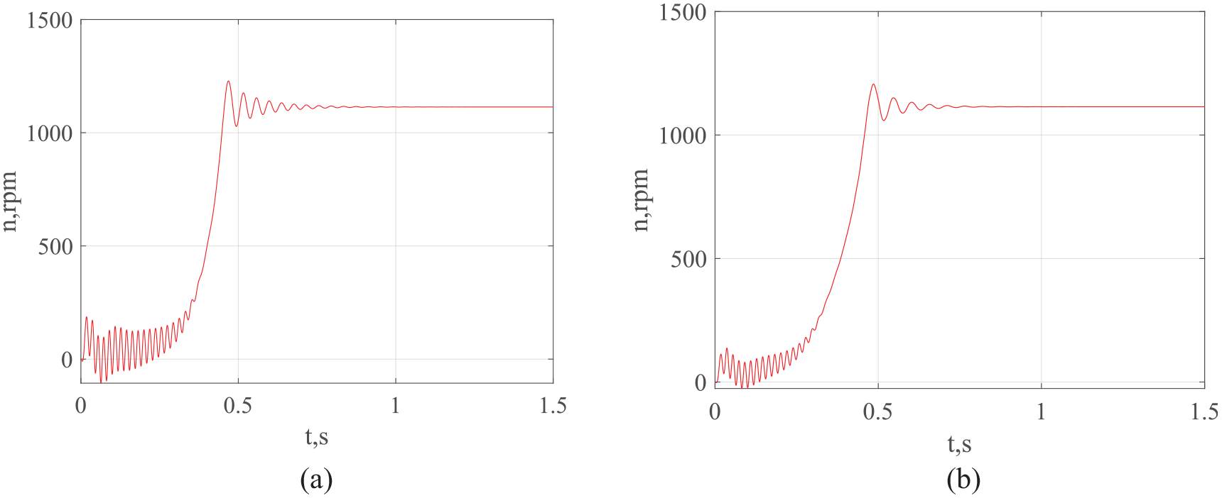
- diagrams of the rotation frequency of the IM shaft in a stable mode for the prototype model (Figure 18(a)) and for the proposed model (Figure 18(b)).
Unstable modes in an induction motor depend on a number of factors, in particular, on initial conditions. Moreover, during unstable modes in an induction motor, quasi-asymmetric modes arise, caused by the instability of energy processes. In this regard, the authors decided to limit their research of asymmetric modes in the induction motor windings to only stable modes. Therefore, diagrams of phase currents, torque, and shaft rotation speed of the induction motor in unstable modes are not presented in Figures 16 to 18.

Diagrams of phase currents in stable mode for the prototype model (a) and for the proposed model (b), obtained for the nominal operation mode of the IM with asymmetric windings without taking into account magnetic losses in steel.

Torque diagrams in stable mode for the prototype model (a) and for the proposed model (b), obtained for the nominal operating mode of the IM with asymmetric windings without taking into account magnetic losses in steel.
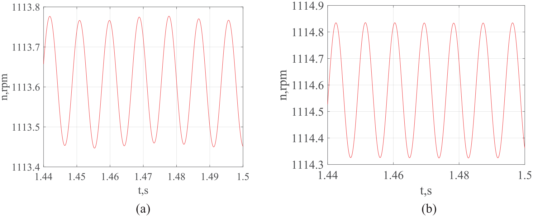
Diagrams of the frequency of rotation of the IM shaft in a stable mode for the prototype model (a) and for the proposed model (b), obtained for the nominal mode of IM operation with asymmetric windings without taking into account magnetic losses in steel.
The asymmetric mode was set as follows. The active resistance of the winding is determined in accordance with equation (42). 32
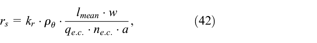
where kr– coefficient of increase in the active resistance of the winding phase due to the effect of the current displacement effect;
ρθ– specific resistance of the material at the calculated temperature;
lmean– the average length of the winding;
w– the number of windings turns;
qe.c.– cross-sectional area of an elementary conductor;
ne.c– the number of elementary conductors;
a– the number of parallel branches of the stator phase.
As can be seen from expression (45), the active resistance of the winding has a linear dependence on the number of turns. Therefore, when organizing an asymmetric mode, the active resistance of the winding of the damaged phase was determined as

where rs– the nominal value of the active resistance of the stator winding;
w– the nominal number of turns of the stator winding;
w′– the number of undamaged turns of the stator winding.
The analysis of formulas (12) and (15) shows that the dissipation inductance has a quadratic dependence on the number of turns of the stator winding. Therefore, when organizing an asymmetric mode, the dissipation inductance of the winding of the damaged phase was determined as
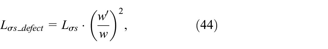
where Lσs– the nominal value of the dissipation inductance of the stator winding.
It was assumed that five turns of the stator winding of phase a were damaged. For this purpose, the number of windings for this phase of the stator winding in “Parameter block of the IM” has been reduced by five. In “Stator phase current determination unit” the value of the active resistance of the stator winding and the dissipation inductance of phase a, calculated according to formulas (43) and (44), respectively, were set.
The instantaneous values of the stator phase current, the minimum and maximum value of the torque, the minimum and maximum value of the rotation frequency of the shaft of the induction motor, and the frequency of torque pulsations were obtained. The results are listed in Table 3. Based on the obtained values of the maximum and minimum torque, the average value of the torque and the torque ripple coefficient were calculated.
The average value of the torque was determined as 12

where Tmax, Tmin– the maximum and minimum torque values, respectively.
The torque ripple coefficient was determined as12,13
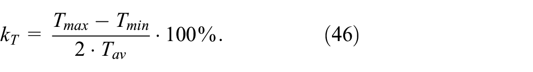
The results of the calculations are listed in Table 3.
Based on the results of the instantaneous values of the phase currents of the stator, the unbalance coefficient is determined

where Imax, Imin– the maximum and minimum instantaneous value of the stator phase current, respectively;
Inom– nominal value of the stator phase current (Table 1).
The result of the calculations is listed in Table 3.
Based on the obtained values of the maximum and minimum rotation frequency of the IM shaft, the average value and the coefficient of instability of the rotation frequency of the IM shaft were calculated. The average value of the rotation frequency of the IM shaft was determined as

where nr_max, nr_min– the maximum and minimum torque values, respectively.
The coefficient of instability of the induction motor shaft rotation was determined as

The result of the calculations is listed in Table 3.
Simulation results for symmetrical windings of an IM with taking into account magnetic losses in steel
The following characteristics were obtained for the nominal mode of operation of an IM with symmetrical windings with taking into account magnetic losses in steel (experiment 3) on the prototype model and the proposed model:
- diagrams of phase currents in stable mode for the prototype model (Figure 19(a)) and for the proposed model (Figure 19(b));
- torque diagrams for the prototype model (Figure 20(a)) and for the proposed model (Figure 20(b));
- diagrams of the rotation frequency of the IM shaft for the prototype model (Figure 21(a)) and for the proposed model (Figure 21(b)).
Diagrams of phase currents in a stable mode for the prototype model (a) and for the proposed model (b), obtained for the nominal operating mode of the IM with symmetrical windings with taking into account magnetic losses in steel.

Torque diagrams for the prototype model (a) and for the proposed model (b), obtained for the nominal operating mode of the IM with symmetrical windings with taking into account magnetic losses in steel.
Diagrams of the frequency of rotation of the IM shaft for the prototype model (a) and for the proposed model (b), obtained for the nominal operating mode of the IM with symmetrical windings with taking into account magnetic losses in steel.
For a stable mode, the instantaneous values of the stator phase current, torque, and rotation frequency of the IM shaft are obtained. The results are listed in Table 3.
Simulation results for asymmetrical windings of an IM with taking into account magnetic losses in steel
The following characteristics were obtained for the nominal mode of IM operation with asymmetrical windings without taking into account magnetic losses in steel (experiment 4) on the prototype model and the proposed model:
- diagrams of phase currents in stable mode for the prototype model (Figure 22(a)) and for the proposed model (Figure 22(b));
- torque diagrams in a stable mode for the prototype model (Figure 23(a)) and for the proposed model (Figure 23(b));
- diagrams of the rotation frequency of the IM shaft in a stable mode for the prototype model (Figure 24(a)) and for the proposed model (Figure 24(b)).

Diagrams of phase currents in stable mode for the prototype model (a) and for the proposed model (b), obtained for the nominal operation mode of the IM with asymmetric windings with taking into account magnetic losses in steel.
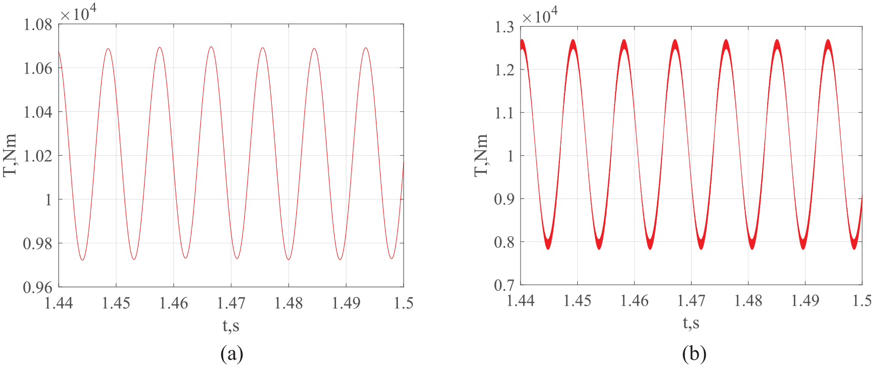
Torque diagrams in stable mode for the prototype model (a) and for the proposed model (b), obtained for the nominal operating mode of the IM with asymmetric windings with taking into account magnetic losses in steel.

Rotation frequency diagrams of the IM shaft in stable mode for the prototype model (a) and for the proposed model (b), obtained for the nominal operating mode of the IM with asymmetric windings with consideration of magnetic losses in steel.
Diagrams of phase currents, torque, and motor shaft speed of an induction motor during transient processes are not very informative, so they are not shown here.
The asymmetric mode of the windings on the IM simulation model was implemented according to the algorithm given in part “Simulation results for asymmetric IM windings without taking into account magnetic losses in steel.”
Based on the obtained maximum and minimum values of the torque, the average torque value (45) and the torque ripple coefficient (47), the imbalance coefficient of the stator phase current (47), the average value (48), and the instability coefficient of the IM shaft rotation frequency (49) were determined. The results are presented in Table 3.
Assessment of accuracy of modeling results
The results of determining the controlled parameters are summarized in Table 3.
According to the results of Table 3, for the mode with symmetrical windings, taking into account the magnetic losses in the steel of the induction motor, the errors in determining the controlled parameters were calculated. The nominal values of the controlled parameters are taken as basic values (Table 1). Errors were determined in accordance with the formula

A– the value of the controlled parameter (Table 3);
Anom– the nominal value of the monitored parameter (Table 3).
As can be seen from the results of Table 4, the controlled parameters determined using the proposed model have smaller errors than the parameters determined using the prototype model. Thus, the error of determining the phase currents of the stator decreased by 2.2%, the error of determining the torque decreased by 1.27%, and the error of determining the rotation frequency of the IM shaft – by 0.15%.
Results of calculation of modeling accuracy.

Discussion
The simulation process of the induction motor of the vehicle, taking into account magnetic losses in steel, was performed in the MATLab/Simulink software environment. When developing a mathematical model, an induction motor was considered as a generalized electric machine. Magnetic losses in the steel of an induction motor are taken into account by introducing variable resistances into the electrical circuits of the stator and rotor, which are a function of instantaneous magnetic losses. Instantaneous magnetic losses were determined according to the method given in works.43,44
Comparison of the simulation results obtained from the prototype model and the proposed model yielded the following outcomes:
- in the nominal operating mode of the induction motor (IM) with symmetric windings, without considering magnetic losses in the steel, the controlled parameter values are practically identical in stable conditions (Figures 13–15, Table 3). For stable operation with asymmetric windings, it can be easily demonstrated that equation (7) equals the equation for determining the torque in the prototype model. 43 This fact can be explained by the properties of trigonometric functions;
- in the nominal operating mode of the induction motor with asymmetric windings, without considering magnetic losses in the steel, the controlled parameter values significantly differ in stable conditions (Figures 16–18, Table 3). Additionally, the values of stator currents, torque pulsations, and the frequency instability coefficient of the motor shaft are higher for the proposed model. This is due to the following fact: for stable operation with asymmetric windings, equation (7) introduces additional sinusoidal components not accounted for in the prototype model. This leads to an increase in torque pulsations on the motor shaft in the proposed model compared to the prototype;
- in the nominal mode of IM operation with symmetrical windings, with taking into account magnetic losses in steel, in a stable mode, the values of the controlled parameters differ significantly (Figures 19–21, Table 3). This is explained as follows. The prototype model took into account the average magnetic losses in steel for the period. The prototype model accounted for average magnetic losses in the steel over a period. These losses are a function of the motor shaft rotation frequency, varying from zero to maximum values. However, in the prototype model, the consideration of magnetic losses was implemented by increasing the load torque, that is, in the mechanical part of the induction motor (IM). Magnetic losses occur in the electrical part of the IM. Since the mechanical part’s inertia is much greater than that of the electrical part, these facts lead to an incorrect consideration of magnetic losses in the prototype model. The proposed model incorporates instantaneous magnetic losses, accounted for during the development of the simulation model of the IM’s electrical part. This allowed for greater convergence of results in stable conditions. The proposed approach of considering magnetic losses by reducing the inertia of the electrical part of the IM is more appropriate, even for transient conditions;
- in the nominal mode of IM operation with asymmetrical windings, with taking into account magnetic losses in steel, in a stable mode, the values of the controlled parameters differ significantly (Figures 22–24, Table 3). The comparison of the results for this regime proves the correctness of the conclusions of the previous paragraphs.
The proposed approach to modeling IM is based on the theory of generalized electric machines. Therefore, it can be used for modeling other types of electric machines, including synchronous machines and induction generators. However, when modeling another type of electric machine, the following factors should be taken into account. The algorithm for determining inductances can only be applied to not salient pole electric machines. For salient pole machines, the algorithm needs to be adjusted according to the theory of generalized electric machines. Regarding magnetic losses in the steel of electric machines, when developing the mathematical model for other types of machines, the following factors need to be considered:
- dimensional and weight parameters of the motor;
- winding geometry;
- properties of the magnetic material used in the construction elements of the electric motor.
According to these parameters, it is necessary to adjust the algorithm for determining magnetic losses in the steel of the motor being modeled.
The continuation of this work can be works devoted to the improvement of control systems for induction traction motors of electric transport and the development of functional diagnostics systems as part of a traction drive with induction motor.
Conclusions
In this work, the improvement of the mathematical model of the induction motor is proposed at the expense of its image as a generalized electric machine. The simulation model of an induction motor was executed in the MATLab/Simulink software environment.
The proposed simulation model is made in three-phase coordinates, which will allow to carry out research in case of asymmetry of the supply voltage system without applying additional structural changes in the simulation model.
The application of the technique, which establishes the relationship between the geometric parameters of an induction motor and its inductances, allows to conduct a study of its operation in conditions of asymmetry of its windings. At the same time, it is not necessary to change the structure of the simulation model, but the number of undamaged turns of the stator winding or the number of undamaged rotor rods should be changed in the model.
Taking into account the magnetic losses in its elements by introducing variable active resistances into the circuits, which are functions of instantaneous magnetic losses, allows conducting research during the operation of an induction motor as part of a traction drive, taking into account the peculiarities of the operational modes of electric transport.
The simulation results obtained on the proposed simulation model were compared with the simulation results obtained on the prototype simulation model. The comparison results indicate:
- a greater convergence of controlled parameters obtained in stable mode on the proposed model with the parameters claimed by the manufacturer. This fact is important for the development of systems for both functional and bench diagnostics of the IM technical condition;
- about the difference in parameters such as the time dependence of torque and the time dependence of stator phase currents during unstable modes. This circumstance is explained by the prototype model having greater inertia in assessing the impact of instantaneous losses on the electromechanical characteristics of IM than the proposed one. This fact is important when building systems for both functional and bench diagnostics of the IM technical condition;
- about the more accurate determination of controlled parameters in asymmetric winding modes of IM. This circumstance is explained by the consideration in the proposed model of instantaneous magnetic losses in the steel due to voltage drops in the corresponding stator and rotor windings and the torque calculation as a function of the IM shaft rotation angle. This fact is important for building systems for both functional and bench diagnostics of the IM technical condition. Thus, determining torque pulsations with greater accuracy will allow for more accurate diagnostics of the IM technical condition using vibration methods. Greater precision in determining instantaneous stator current values will enable more accurate diagnostics of the IM technical condition using current method;
- about the possibility of applying the proposed approach to implement the consideration of magnetic losses in the steel for the development of IM thermal model.
The listed advantages of the proposed model determine the direction of further work, namely:
- applying the IM simulation model in the research of traction drive systems considering the specific operating modes of electric transport;
- applying the IM simulation model in the development and research of functional diagnostic systems of traction drive system elements;
- studying the IM operation considering thermal operating modes as part of an electric transport traction drive system.
Footnotes
Handling Editor: Chenhui Liang
Declaration of conflicting interests
The author(s) declared no potential conflicts of interest with respect to the research, authorship, and/or publication of this article.6
Funding
The author(s) received no financial support for the research, authorship, and/or publication of this article.