
Abstract
Aerial aquatic vehicles have wide prospects in scientific and industrial fields because of their cross-domain locomotion ability. To improve the operation capacity of aerial aquatic vehicles, a novel multimodal hybrid vehicle was proposed in this paper. The vehicle combined the advantages of fixed-wing aircraft and multirotor aircraft. Owing to the special morphing wing and tilting rotors mechanism, the vehicle was reconfigurable to adapt to a variety of missions, including long distance flight, vertical take-off and landing, and underwater locomotion. The structure of the hybrid vehicle was designed, and the operating method in different modes were discussed. Then the kinematic and dynamic models were analyzed in terms of fixed-wing flight, multirotor flight, and underwater operation modes, respectively. The attitude control and a control allocation algorithm were established for locomotion control. Finally, the experiments of air flight, morphing wing, and underwater motion were conducted. The results showed that the hybrid aerial aquatic vehicle performed good flight stability and could move freely underwater. The morphing wing could fold and expand itself for resistance reduction and long-distance flight, respectively. The multimodal locomotion experiments verified the feasibility of the novel aerial aquatic vehicle and the control strategy.
Keywords
Introduction
In recent years, aerial aquatic hybrid vehicles have attracted much attention over the world. As traditional Unmanned Aircraft Vehicle (UAU) and Unmanned Underwater Vehicle (UUV) can only move in single environment, which limits their operation space, application scenarios, and emergency capacity, there is increasing interest in developing multi-modal vehicles which can operate both in the air and underwater and transition seamlessly between the two mediums. Aerial aquatic hybrid vehicles, which combine the multiple maneuverability and advantages of UAV and UUV, can be deployed in many specific tasks. For example, different from the traditional UAV and ship collaborative search and rescue, aerial aquatic vehicle can carry out wide range search and complete maritime rescue tasks alone, which effectively improves the rescue capabilities and reduces risks. It can be also deployed for disaster relief after floods or tsunamis. 1 As it can carry out air and underwater exploration at the same time, the hybrid vehicle has more advantages in Geographic Information System (GIS) mapping and seabed map drawing. 2 In addition, it can carry out marine ecological monitoring and water quality parameter collection. In the future, water-land-air relay communication can be realized by multiple aerial aquatic vehicles’ networking. Owing to the multi-terrain mobility, aerial aquatic hybrid vehicles are not only applicable to scientific and industrial fields, including oceanography, agriculture, marine life surveys, submerged structure inspections, and off-shore sampling,3–5 but also advantageous in military application, such as reconnaissance, target tracking, and costal patrols.
The typical aerial aquatic hybrid vehicles are mainly consisting of three subtypes: fixed-wing based vehicles, multirotor based vehicles, and hybrid vehicles.6,7 Many of the early aerial aquatic vehicles were expanded from the common layout of fixed-wing aircrafts, which were propelled by rotors or jets, lifted by symmetrical wing, and stabilized by control surfaces. Moore et al. 8 proposed a carbon-fiber-made triangular fixed-wing aerial aquatic vehicle and demonstrated the tilt water exit method, which was verified by experiments. The similar layout was also developed by Wei et al. from Shanghai Jiao Tong University. 9 With a shape like a manta ray and two horizontal propellers symmetrically arrayed on the delta-wing, the vehicle could rapidly exit from water with a wide range of pitch angles. Another prototype named SUWAVE developed by Sherbrooke University used a rotating body to realize passive vertical takeoff, which prevented mechanism and control of wing folding. 10 Weisler et al. 11 and Stewart et al.12,13 designed and improved a hybrid UAV–UUV, which adopted an orthodox wing and Vertical Takeoff and Landing (VTOL) tailsitter configuration. Using a flooding and draining wing, the vehicle could manage buoyancy passively and maintain the proper weight in both water and air. Rockenbauer et al. 14 designed an aerial-aquatic hybrid vehicle (Dipper). It was equipped with an actively swept wing to reduce impact and resistance at water entry and underwater cruising motion. Zufferey et al. 15 proposed a sailing micro air vehicle that could land and take-off on water surfaces, named SailMAV. SailMAV used a three-part folding wing design, which could be reconfigured and thus converted into flying and sailing mode. However, it was not equipped with submerging function. Siddall and Kovac 16 developed an aquatic micro air vehicle (AquaMAV), which was able to perform fast aquatic escape with a jet thruster and predict escape trajectories.
To find new methods of water exit, researchers from Imperial College London used water-reactive fuel to produce combustible gas to rapidly escape water. 5 However, this chemical combustion was not repeatable, so limited the continuous work of the vehicle. The above mentioned fixed-wing aerial aquatic vehicles have made great progress in terms of multi-modal locomotion. However, they should generally dive into water at high speed, which exerts huge impact on the vehicle and may cause structural damage. Another glide landing way is gentler but less adaptable because it needs larger space and longer time. Although fixed-wing vehicles can achieve high speed with less consumption, it is less practical in terms of stability and flexibility, especially at low speed and in narrow space.
To overcome the above shortcomings of fixed-wing type vehicles, the multi-rotor aerial aquatic vehicles rose gradually because of their VTOL and hovering capabilities and the flexible control strategy. Chen et al. 17 proposed a quadrotor aerial and underwater vehicle and explored the control stability in cross-domain process. Alzu’bi et al. 2 developed the Loon Copter which used a single set of motors and propellers for air and underwater locomotion. With an active buoyancy control mechanism, Loon Copter could adjust buoyancy and center of mass simultaneously to change the pitch angle and propulsion direction. In addition to these one-layer rotors structure, some researchers were working with two-layer layout. Maia et al. 18 improved an octo-quadcopter cross-domain vehicle (Navigator). The dual-layer configuration ensured there were always enough rotors working continuously and thus enabled the Navigator seamlessly transition through the air-water surface. Horn et al.19,20 also proposed a hybrid aerial underwater vehicle (HyDrone) with two layers rotors configuration. By replacing the lower layer with aquatic screw propellers, they verified that the propulsion efficiency could be improved. The combination design of aerial and aquatic propellers and the control method was also explored by Ma et al. from Air Force Engineering University. 21 Despite more efficient by using two sets of propellers, this redundant design also increased structure weight and control complexity. Tan et al. 22 proposed a propulsion system which used a gearbox to switch the output speed and then enabled the same propeller operate efficiently both in air and underwater.
Although the above fixed-rotor layout could realize horizontal motion, the entire vehicle should be rotated to large angles to produce larger component of thrust to overcome fluid resistance, so it is difficult to install and balance a camera or manipulator. Therefore, tilting rotors became an optimization. Tan and Chen23,24 developed an aerial aquatic quadrotor using morphing structure. Using a coupled gear transmission mechanism, the four rotors could be tilted equally and simultaneously by one common servo motor. When the tilting angle was 0°, 90°, and 180°, the vehicle worked efficiently in air motion, lateral motion, and dive motion, respectively. Later an improved version was developed which used an independent tilting mechanism, so each rotor could tilt at desired angle, allowing for more combinations of the thruster configuration. 25
The multi-rotor configuration has the advantages of VTOL and hovering capacity and control flexibility, which is essential in cross-domain motion and control. However, it is accompanied with non-streamlined shapes and low cruising efficiencies. 9 To make full use of the advantages of multi-rotor and fixed-wing, there are recent researches to combine two propulsions into a hybrid cross-domain vehicle. Shanghai Jiao Tong University has developed a series of hybrid aerial underwater vehicle.6,26–28 In 2018, they proposed the Nezha II which was consisting of four rotors and a pair of wings; simulation and experiments revealed that the vehicle was feasible in VTOL mode, underwater glide mode, and forward flight mode.26,29 Then in 2021 they proposed an improved version Nezha III which adopted motor arms folding mechanism for better hydrodynamics and pneumatic buoyancy system for payload and weight regulation. 27 In 2022, another configuration of Nezha III was developed, which combined vertical four rotors with a fixed-wing aircraft. 28 However, the rotors were not used in underwater locomotion as it was vertical to the wing. Besides, the large span wing would cause aerodynamic drag on multi-rotor flight.
From the analysis above, the current researches have achieved much improvement for the design and control of aerial aquatic vehicles. Nevertheless, it is still a challenge to balance the speed, stability, maneuverability, and operation capacity. Hybrid aerial aquatic vehicles, as a combination of fixed wing and multirotor, have many significant advantages. However, the existing hybrid aerial aquatic vehicles should be further improved in terms of dynamic allocation and fluid shape design. The main contribution of this paper is providing a novel design and experimental validation of an aerial aquatic hybrid vehicles capable of reconfiguration, VTOL, and multimodal locomotion. The vehicle is featured with a pair of morphing wings, a V-tail wing, and three tilting rotors. By tilting the two front rotors, the vehicle can freely switch between fixed-wing and multirotor modes, which are responsible for long distance fast transport and VTOL and precision control, respectively. The vehicle can be further transformed to underwater mode when it is submerged. Besides, the resistance during water entry, water exit and underwater navigation can be greatly reduced by folding the wing. Most importantly, the vehicle is capable to enter and exit water by VTOL in multirotor mode, which prevents the huge impact and possible damage to the vehicle.
The rest of this paper is organized as following. Section “Design and implementation” illustrates the design and implementation of the hybrid aerial and aquatic vehicle. The dynamic model and control strategy are established in Section “Model and control system.” Section “Experiments” presents the fabrication of the vehicle prototype and the initial experiments. Conclusion is finally given in Section “Conclusion.”
Design and implementation
Overview
As there are huge fluid differences between water and air in terms of density, buoyancy, and resistance, the abrupt changes from air to water may lead to problems such as mechanical structure damage, current peaks of motors and attitude instability. 20 The fluid buoyancy and resistance of water and air have difference impacts on the vehicle motion, which leads to different demands of weight, volume, and control strategy. We are motivated to propose a novel hybrid aerial aquatic vehicle which can achieve smooth vertical transition between water and air. Besides, we hope the vehicle is capable to switch between high-speed cruise and low speed hovering, which are responsible for long distance task and precise position control, respectively. Therefore, we proposed the following design principle for the multimodal reconfigurable aerial aquatic hybrid vehicle.
(1) VTOL ability. The vehicle should be able to carry out vertical takeoff and landing smoothly and stably. Therefore, multirotor arranged vertically is the prior choice.
(2) Fixed-point hovering. The hovering function is necessary for photographing and observation.
(3) High speed flight capacity. To achieve fast mobility in a wide range both underwater and in air, fixed wing with horizontal-driven propellers is the best scheme because it can not only achieve high speed movement, but also energy saving.
(4) Low impact at domain transition process and underwater motion. Although the long span wing helps generate larger lift in air, it tends to increase the resistance in the process of water entry, water exit, and underwater cruse. Therefore, folding wing can be used as an optimization approach, which has been proven by Rockenbauer et al. 14
To meet the above requirements, we proposed a novel fixed-wing and multirotor hybrid aerial aquatic vehicle. As shown in Figure 1, the profile of the vehicle is based on a V-tail fixed-wing aircraft, which is integrated with three rotors. The rear rotor is fixed upwards; and the front two rotors are symmetrically installed on the wing and can be tilted in a large range, thus providing vectored thrust. When the propellers are horizontal, the vehicle works as fixed wing. When the propellers are tilted upwards, the vehicle can be operated as a multirotor, in which case it can conduct VTOL and hovering. The high-aspect-ratio wing is separated into two parts. The outer part can rotate and sweep back around the inner part, thus folding the entire wing. This morphing mechanism can change the wing shape to reduce the resistance when moving underwater and crossing domains.

The concept design of the reconfigurable aerial aquatic hybrid vehicle.
The main design parameters are listed in Table 1. Owning to the morphing wing and the tilting rotors, the vehicle is reconfigurable and the dimension is variable. The wing span is 1.76 and 1.0 m when the wing is fully extended and folded, respectively. The rotors are designed to tilt freely in a wide range of 180°, so the total height changes from 0.18 to 0.25 m.
The design parameters.

Operating method
Based on the unique configuration, the hybrid vehicle can switch between multiple modes and thus adapt to a variety of tasks in different environments. According to operating method, we define the following working modes: Fixed-wing flight mode, multirotor flight mode, and underwater mode. The VTOL function, as a special case of multirotor flight mode, is utilized to carry out water ingress and water egress.
When the vehicle is working in the air, the whole flight is further divided into three stages: fixed-wing mode, multirotor mode, and conversion mode. Fixed-wing mode is defined when the vectored rotors keep parallel with the fuselage. When the vectored rotors are approximately vertical to the fuselage, it is multirotor mode. The conversion mode is the transient process between multirotor mode and fixed-wing mode. During the full flight mission, the vehicle undergoes multiple stages including vertical takeoff, multirotor mode, conversion mode, fixed-wing mode, conversion mode, multirotor mode, and vertical landing, as shown in Figure 2. The vehicle takes off from the ground or water surface and flight at low speed in the multirotor mode. After reaching a certain safe height, it is adjusted to the conversion mode and the front two rotors begin to tilt forward. Keeping the body stably, the forward flight speed is increasing and the rotors continue to tilt until they are horizontal. When the air speedometer reaches a certain speed, the two rotors are completely tilted forward and the vehicle becomes fixed-wing mode. After the long-distance transport is completed, the vehicle enters the conversion mode again. The two rotors gradually tilt back to the vertical state, and the forward speed decreases until entering the multirotor mode. Finally, the motor speeds are reduced to realize smooth vertical landing. If water ingress instruction is issued, the vehicle firstly folds the wing, and then makes a vertical landing to the water surface. The underwater mode is further carried out for water locomotion.

The working flow of the vehicle at dry flight process.
The hybrid aerial aquatic vehicle adopts different control strategies to adjust the attitude and spatial position under different operating modes, as shown in Table 2. The black arrow denotes the direction of the propeller’s thrust, with the length of the arrow representing the magnitude of this force. The red arrows signify the rotational directions of the tail and ailerons. (1) Multirotor mode. By increasing or decreasing the speed of three motors simultaneously, the vertical upward or downward movement can be realized. The pitch motion is realized by the differential speed of the front and rear motors. The forward and backward motion is indirectly controlled by adjusting the pitch angle of the vehicle, during which the rotor generates a component force in the longitudinal direction. The rolling motion is achieved by the differential speed of the front left and right motors. By controlling the differential angle of the front vectored rotors, the yaw motion is realized. For example, when the right motor tilts forward and the left motor tilts backward, the vector thrusts produce a yaw moment to the right. Like quadrotors, the longitudinal movement and the lateral movement are coupled with pitch angle control and the roll angle control, respectively. (2) Fixed-wing mode. The thrusts of the vector motors are fixed forward in fixed-wing flight; and the propeller’s thrust serves as the driving force for navigation. The attitude adjustment is implemented by control surfaces. The roll angle is changed by the ailerons’ differential motion. The V-tails are responsible for pitch and yaw angle control. When the V-tails move at the same direction, pitch moment is generated; and yaw motion is realized when the V-tails move at opposite direction. Similarly, the depth control is achieved by change the pitch angle of the vehicle. (3) Underwater mode. As the vehicle is designed with neutral buoyancy, the propellers are mainly used for attitude stabilization and depth control instead of overcoming the gravity. Unlike in air, the vectored rotors can be tilted to point either upward or downward in the water to provide an upward or downward component force, respectively. The pitch angle not only can be controlled by adjusting the tilting angle and speed of the two vectored rotors, but also can be changed by the V-tail, like the case in fixed-wing flight. Similarly, the roll angle can also be controlled by both the rotors and the V-tail. The yaw angle is controlled by the speed differential of the vectored rotors.
The control strategies of the hybrid aerial aquatic vehicle under different operation modes.

Structure design
Morphing wing mechanism
At the water ingress phase, the inevitable impact may cause damage to the vehicle components, especially the wing. Learning from the nature, many researches have adopted bionic method when designing cross-media UAVs. They refer to the living habits and movement patterns of amphibians to realize the transition of different media, such as flying fish, bonito, and cormorant. Kingfisher, which lives on fish and shrimp in the water, often inhabits on the shore branches. When finding preys, kingfisher adjusts its wing swept back from the winged flight state to make the body streamlined. Then it dives down at a certain acceleration and quickly plunges into the water to capture targets, with a speed of up to 20 m/s. Taking kingfisher as the bionic object, the bionic modeling is carried out by using reverse engineering to capture and analyze the changes of the kingfisher’s posture during the water entry process, to imitate the water entry mode of reducing the impact by swept wings. The attitude changes of the kingfisher from the air to the water and the corresponding attitude of the bionic aerial aquatic vehicle is shown in Figure 3.

The attitude comparison of kingfisher and the hybrid aerial aquatic vehicle.
The bionic aerial aquatic vehicle is equipped with a large wingspan for high efficiency fly, while a shorter wing is required to reduce the dive impact and underwater locomotion resistance. So, we have designed a novel morphing wing, which are mainly divided into two parts: the inner fixed wing connected to the fuselage and the outer movable wing. The two parts are connected by an active joint and the interface is inclined at an angle of 45° to the chord. The transmission mechanism inside the wing is shown in Figure 4(a). The deformation unit is set within the inner wing, which is installed on a fixed frame, and two carbon tubes are employed to reinforce the structure. The morphing wing mechanism demands merely one steering gear, whose output shaft is linked to the rotating seat via a coupling. Under the actuation of the steering gear, the outer wing can rotate around the inner wing and eventually achieve swept-back folding. Assume that the initial angle of the steering gear is 0, corresponding to an angle of 0 between the inner and the outer wings. When the output angle of the steering gear is
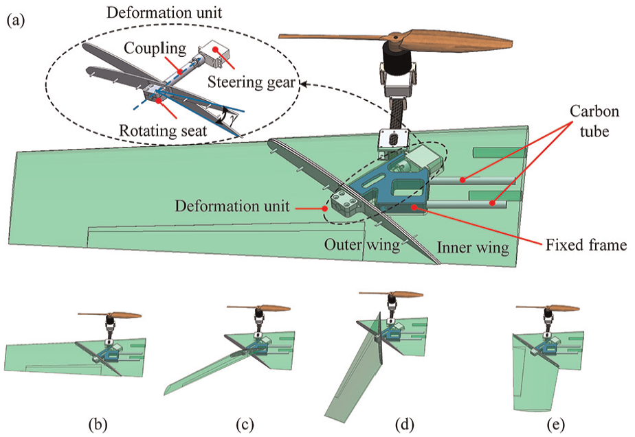
The mechanism of the morphing wing: (a) the inner structure of the morphing mechanism, (b) the state when the steering gear angle is 0° and the wing is fully spreading, (c) the state when the steering gear angle is 45°, (d) the state when the steering gear angle is 90°, and (e) the state when the steering gear angle is 180° and the wing was fully folded.
Tilting rotors mechanism
The front two propellers are the key factor for the vehicle to realize the switch between multi-rotor mode and fixed-wing flight mode, which are also essential for water entry and water exit. The mode conversion is completed by the tilting rotors. Compared to complex mechanisms such as gear transmission, linkage transmission, and chain transmission, the direct drive method is more simple, more reliable, less transmission clearance, and lower weight. The tilting mechanism is shown in Figure 5. The two shaft steering gears are installed on the carbon square tube. By tightening the screws, the steering gear and the two clamping chunks are fixed on the carbon tube. The rotor motor is connected to the steering gear via a motor seat and two swing arms. Under the actuation of the steering gear, the swing arms drive the motor and the propeller to rotate within a maximum 180° range.

The tilting mechanism of vectored rotors.
The position of the tilting propeller has a certain distance from the carbon square tube. This distance should be long enough to reduce the load generated by the downwash airflow of rotors, which has a negative effect on the upper surface of the wing and affect the lift force. According to the momentum theory of the propeller slipstream, 30 the induced velocity at a certain distance at the downstream or upstream position of the propeller disk is calculated in equation (1).

where
The continuity equation of incompressible fluid in steady flow is

where

According to the design parameters of the vehicle, when the propeller is tilted to be vertically upward, the downwash airflow area on the wing is shown in Figure 6. The interaction area accounts for a small proportion of the propeller rotation plane and the wing area, which means that the influence can be ignored.

The interaction area of the downwash airflow on the wing.
Avionics system
The airborne avionics system is responsible for motion control, mode switching, and mission planning of the vehicle. The flight controller is the core component which should meet the requirements of powerful function, high reliability, and small volume. We chose Pixhawk as the controller hardware and carried out the secondary development based on its open-source code. As a widely used flight controller, Pixhawk has advanced processor and sensor technology, as well as the real-time operating system. Besides, the avionics system concludes various sensors, motors and actuators, batteries, and communication modules. The schematic diagram is shown in Figure 7. The Pixhawk receives SBUS signal from the receiver, which is connected with the handheld remote controller wirelessly through 2.4G network. The basic motion control and mode switching instructions are delivered via remote controller. GPS, IMU and airspeed meter are used for positioning and attitude control, which plays an important role in multi-task modes. Airspeed meter can also measure the flight speed of the vehicle, which provides a judgment basis for mode switch. The telemetry updates the motion data to the computer, and displays the vehicle position, attitude, battery data and video picture in the ground station software. The whole system is powered by a 24 V lithium battery. The voltage regulator reduces the battery voltage to 12 and 5 V, and supplies power to the servos and the controller board, respectively. Besides, the regulator transmits the voltage and current values to the controller in an analog signal, which will be converted and calculated to estimate the current power and the remaining voyage time.
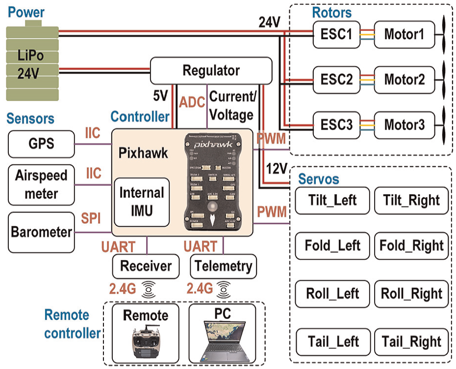
The schematic diagram of the avionics system.
Model and control system
Dynamic model
Kinematic model
The aerial aquatic vehicle is essentially a multi-body dynamics system. Its motion encompasses three degrees of freedom in translation and three degrees of freedom of rotation around the center of gravity. To simplify the model, the following assumptions are introduced.
(1) The vehicle is a rigid body with a constant mass.
(2) Suppose that the ground is a plane and the curvature is ignored.
(3) The compression of air is not considered.
(4) The impact of blade flapping and shimmy are ignored.
(5) The airflow disturbance between the wing and the tilting rotors is not taken into consideration.
(6) Since the tilting rotor rotates at low speed, its gyroscopic effect is ignored.
The different coordinate systems are introduced to describe the mathematical expression of the vehicle’s dynamic and kinematic model, as shown in Figure 8. The earth coordinate system (

The coordinate systems of the vehicle.
The spatial position and attitude of the vehicle in the ground coordinate system is expressed as

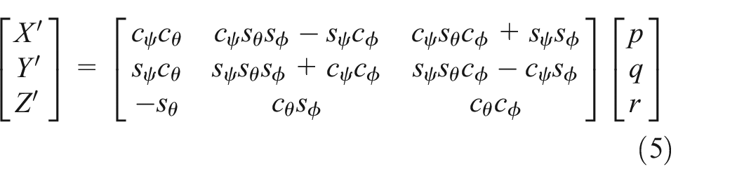
The relationship of the vehicle’s position and attitude in the two coordinates can be calculated by the transformation matrix:

The origin of the airflow coordinate system and the body coordinate system are both established on the CG of the vehicle, and the relationship is determined by the angle of attack (

In the rotor coordinate system, the tilting rotor only needs to rotate around

where
Dynamic model
The hybrid aerial aquatic vehicle can work in multiple modes, including the multirotor mode, fixed-wing mode, and underwater mode. As the actuation force, stabilization strategy and environmental force are totally different in different modes and different media, the dynamic model is established in these three modes respectively.
The multirotor mode
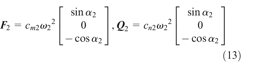
When the vehicle flights at multirotor mode, it is similar with a tri-rotor UAV. According to blade element theory and relative flow theory, 31 the forces and moments imposed on the rotor include lift force (F), resistance (D), reaction torque (Q), and inclination torque (L), which can be expressed as
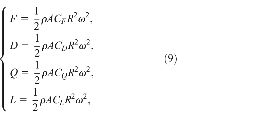
where

The definition of each actuator is shown in Figure 9. The right and left rotors are named as

where

The number of the motors and servos.
Therefore, we can obtain the thrust and reaction torque of two tilting rotors and the tail rotor in body coordinate system:

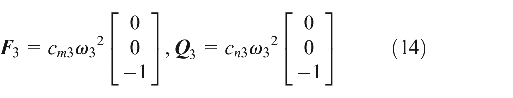
Therefore, the total thrust force of the hybrid vehicle in multirotor mode at body coordinate system can be calculated:

The total reaction torque is

In the body coordinate system, the gravity of the UAV can be expressed as

So, the total force and torque acting on the vehicle is

The fixed-wing mode
In the fixed-wing flight state, the vehicle relies on the thrusts of the front two rotors to provide forward power. The lift force is mainly provided by the aerodynamic shape. The roll, yaw, and pitch moments are generated by the rudder surface. In this mode, the vehicle mainly considers rotor thrusts, gravity, and aerodynamics forces. As the front two rotors tilt to the horizontal position, we get
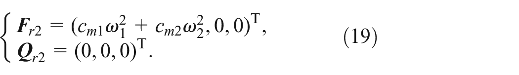
Compared with the T-tail, the V-tail balances the functions of the vertical rudder and the horizontal elevator into two V-shaped tails. Only two servos are needed for yaw angle and pitch angle control. The projection area in the two directions of the top view and the side view can be equivalent to the rudder surface of T-tail. Suppose
where

The expressions of the roll, pitch, and yaw moment are

where b is the wingspan, c is the average aerodynamic chord length of the wing.

As the force and moment in equations (20) and (22) are calculated in the airflow coordinate system (


Therefore, the total force and moment in fixed-wing flight mode is
The underwater mode
When the aerial aquatic vehicle moves underwater, the front two rotors tilt below the fuselage (
Apart from driving force, the vehicle is mainly affected by the gravity, the buoyancy, and the fluid resistance during navigation. Due to the limited diving depth and slow sailing speed of the aerial aquatic vehicle at current development stage, it is assumed that the influence of inertial force and Coriolis force can be ignored. As there are great density and viscosity differences between water and air, the propeller has different thrust coefficient and torque coefficient under water. Suppose the
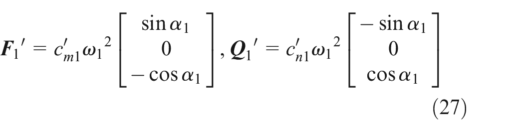


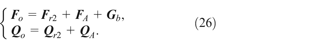
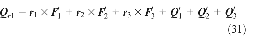
The total force and moment of the cross-media vehicle in the underwater mode are expressed as equations (30) and (31) in the body coordinate system.
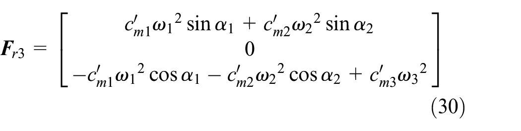
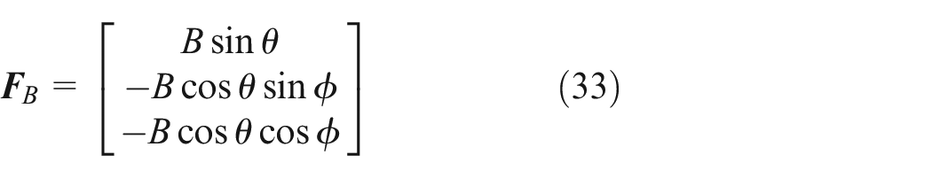
The fluid resistance is calculated by equation (32), where

The buoyancy of the aerial aquatic vehicle is slightly greater than the gravity and the buoyancy center is higher than the gravity center, which provide a certain restoring moment and guarantees the safety of the vehicle in emergency. Suppose the buoyancy in the ground coordinate system is

Therefore, the total force and moment of the vehicle in underwater mode are

Dynamic equation
The spatial motion of the vehicle can be represented by three-axes angular motion and three-axes linear motion. According to Newton-Euler equations, the dynamic equation of the cross-media UAV can be described in the body coordinate system, as shown in equation (36)

where


Control strategy
The bionic hybrid aerial aquatic vehicle is distinguished from conventional aircrafts by the morphing wing and tilting rotors. Thanks to the numerous actuators, the reconfigurable structure, and the cross-domain capacities, the vehicle is combining the advantages of fixed-wing UAV, multirotor UAV, and underwater vehicle. However, it also increases the difficulty of stabilization control. According to the dynamic analysis, the inconsistent mathematical expressions in the different operating modes lead to different controllers. The vehicle should switch between different control modes depending on the actual environments.
The vehicle proposed in this paper is based on a V-tail fixed-wing aircraft, whose dynamic model and flight control method are relatively mature. Besides, there is an existing firmware code in Pixhawk controller that can be applied directly for fixed-wing flight. Therefore, we do not explore the fixed-wing flight algorithm in this paper. In the contrary, we pay main attention to the vertical takeoff and landing capacity, the underwater motion, and the stability in domain transition process.
The six-degree-freedom control strategy can be united to the same framework for multirotor flight mode and underwater mode, as shown in Figure 10. The desired position
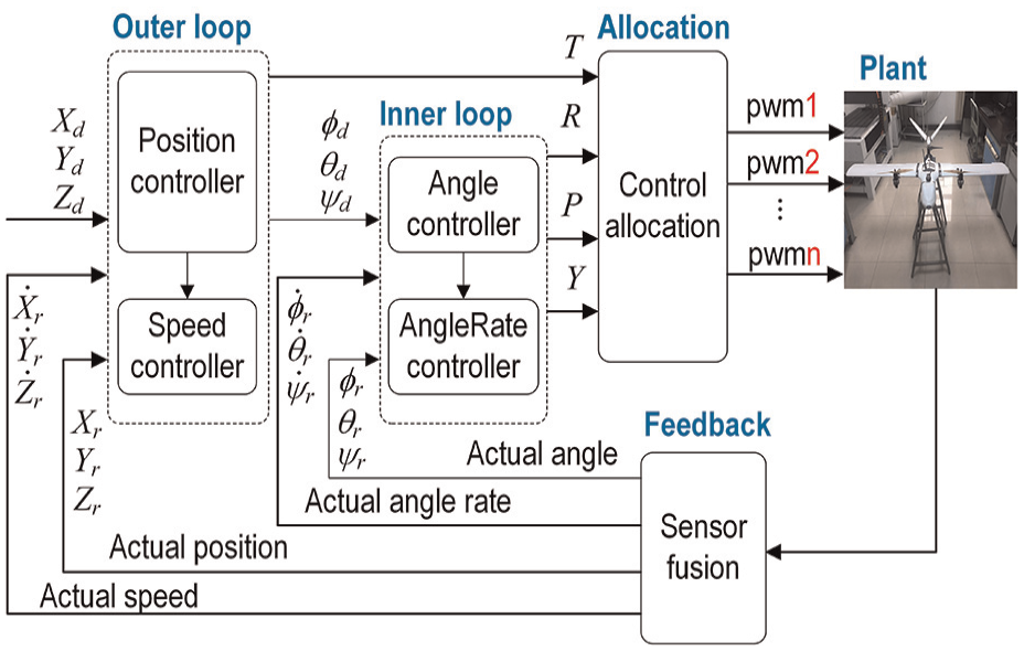
The six-degree-freedom control framework.

The multiple cascade PID controller for attitude and height (depth).
The hybrid aerial aquatic vehicle adopts a multiple cascade proportional-integral-derivative (PID) controller. The three-axis attitude angle and the position in vertical direction are the control objectives. The four control channels use the similar structure. The outer loop compares the desired angle and position with the feedback values. Then a proportional controller is called to calculate the desired speeds, which are then sent to the inner speed loop as the reference signals. The four speed controllers output the pseudo-control vectors
The attitude of the multirotor flight is controlled by the speed of the three rotors and the angle of the two tilting servos, that is,

When the vehicle is in equilibrium position, that is, it is hovering at a fixed point, there is:
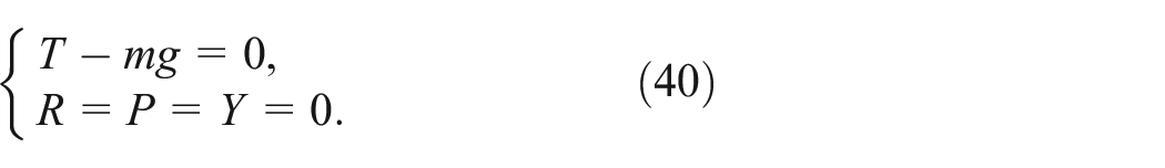
Solving the above equation, it is not difficult to get

Then the tilting angle can be calculated using equation (39).
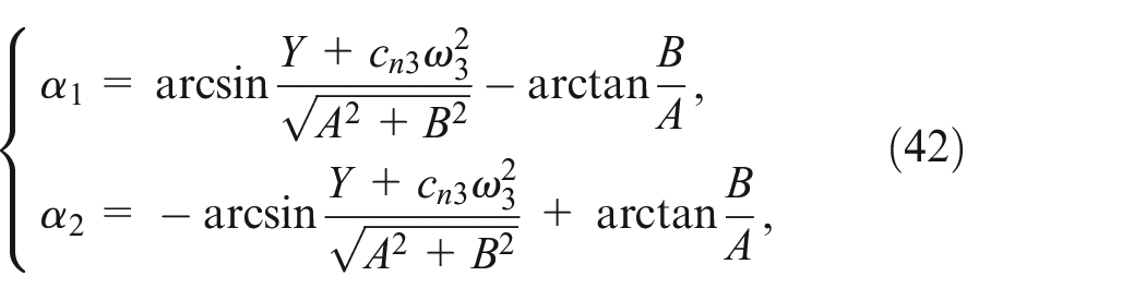
where
Experiments
Prototype
The fabricated hybrid aerial aquatic vehicle prototype is shown in Figure 12(a). The main part of the vehicle body is made by PVC foam for lightweight design. As the strength and stiffness of the foam material are poor, it is a challenge to install the tilting mechanism on the wing. Carbon square tube is chosen as the connection parts because it has high strength and low density. Besides, the hollow hole is convenient for wire arrangement. The folded state of the morphing wing is shown in Figure 12(b).

The hybrid aerial aquatic vehicle prototype: (a) and (b) are the expanded state and the folded state of the morphing wing, respectively.
Air locomotion
The hybrid vehicle took off vertically in multirotor mode and performed attitude and altitude adjustment in real time according to the controller and control allocation algorithm designed in the previous subsection. When the vehicle rose to a certain height, push the throttle rocker of the handheld remote control back to a lower position, and the vehicle was hovering at the current height in self-stabilization control mode. The attitude of the vehicle when hovering at fixed height is shown in Figure 13. It can be seen the vehicle executed the vertical takeoff command smoothly and with good attitude deployment. The attitude angle data was recorded by the ground station software, and the curves are shown in Figure 14. The pitch angle was fluctuating between −3.86° and 2.41°, and the mean value was about −0.4°. The average value of roll angle was about 1.8°. The yaw angle had some oscillation at the beginning and then varied between 5° and 10°. The average yaw angle was about 6.4°.

The vertical takeoff and hovering experiments of the hybrid aerial aquatic vehicle.

The attitude angle changing with time when the aerial aquatic vehicle is hovering at equilibrium position.
The attitude angle curves showed that the vehicle could maintain the attitude for stable flight. However, the angles still suffered from some fluctuations, especially for the yaw angle. On the one hand, the shape of the aerial aquatic vehicle was based on a fixed-wing UAV with a long wingspan, so it was susceptible to disturbance by external drag. Secondly, the three rotors were positioned relatively close to the center of gravity, and they were at a certain distance from the wingtips and the tail of the vehicle, which meant that the roll and pitch moment were relatively small compared to standard multirotor UAV whose rotors were usually arranged at the most external position. Finally, the three rotors were more difficult to adjust the attitude than the standard quadrotors.
The morphing wing experiment were than executed. The wing convergence was completed in the multi-rotor flight mode to reduce the impact of water ingress and the drag during the underwater motion. Controlling the vehicle to descend steadily at a lower speed, morphing command was issued after reaching a certain height above the water surface. The folding and expanding experiment results are shown in Figure 15.
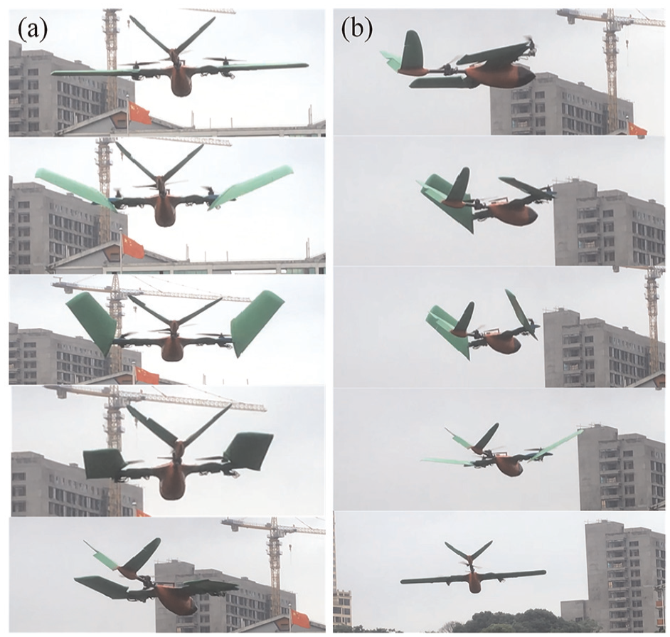
The morphing wing experiments: (a) the folding process and (b) the expanding process.
Furthermore, we did the forward flight experiment. The attitude angle in forward process is shown in Figure 16. The yaw angle was stabilized around 3°, which meant that the vehicle maintained a fixed heading flight. The minimum pitch angle is about −15° during the forward flight. In the final stage, when the velocity was reduced to zero, the pitch angle was also restored to 0°, which verifies the forward flight control strategy in multirotor mode.

The curves of attitude angle versus time when the hybrid aerial aquatic vehicle is flying forward.
Underwater locomotion
The underwater locomotion experiments were conducted in a wild lake. The experimental picture of the vehicle was shown in Figure 17. The vehicle was firstly operated to flight downwards to be near the water surface. Then the morphing command was delivered to the vehicle by the remote control. After the wing was fully folded, the vehicle landed to the water vertically. As the buoyancy was greater than the gravity, the vehicle was sailing near water surface under normal situation. To carry out vertical heave motion, the front two rotors were tilted to below the level of the fuselage. The attitude balance control of the three rotors was similar to the situation in the air, so the attitude control and control allocation algorithm could be also invoked. The difference was that the PID parameters were different. Besides, the tilting angle of the rotors could be more horizontal to provide larger forward component force because the buoyancy provides enough recovery force and moment.

The underwater motion experiment of the hybrid aerial aquatic vehicle.
The attitude and velocity curves are shown in Figure 18. The pitch angle was between 7° and 12°, and the roll angle was around −2° to 1°. In the acceleration stage, the yaw angle showed some deviation. When the thrust was pushed to the maximum, the velocity reached 1.2 m/s. Then we reduced the thrust and the velocity at steady sailing stage was about 0.6 m/s. The velocity was limited because the air propeller was less efficient in the water. The navigation direction was relatively stable in the second half motion. The underwater experiments verified the feasibility of the aerial aquatic vehicle.

The attitude angle and the velocity of the hybrid vehicle in underwater motion experiment.
Conclusion
In this paper, we propose a multimodal hybrid aerial aquatic vehicle with morphing wing and tilting rotors. Owning to the unique configuration of tri-rotors and fixed-wing aircraft, the novel vehicle can switch between fixed-wing flight, multirotor flight, and underwater glide modes. To reduce the resistance in water ingress and underwater navigation process, we equip the vehicle with a special morphing wing, which can be fully folded when the vehicle is entering water. The wing can be expanded again when it is performing long-distance, high-speed flight in fixed-wing flight mode. The conclusion is drawn below:
(1) The flight and underwater locomotion experiments shows that the hybrid scheme is reasonable and practical. The vehicle can carry out vertical takeoff and landing like a multirotor aircraft, and can also flight like a fixed-wing aircraft. The underwater experiments verify its amphibious locomotion capacity. Compared to existing aerial aquatic vehicle that are based on a single type aircraft, the vehicle in this paper has advantages in multimodal maneuverability and flexibility. It combines the advantages of VTOL of multirotor and high speed of fixed-wing aircraft. It also addresses the problems of low-efficiency of multirotor and poor flexibility and low control precision of fixed-wing.
(2) The reconfiguration design of the vehicle is verified to be more flexible and adaptive. The morphing wing helps the vehicle to reduce forward resistance and water entry impact. The tilting rotors can be used for attitude stabilization, vertical takeoff and landing, and forward propulsion, which is realized by controllable variant angles.
(3) The attitude control and control allocation algorithm are proved to be feasible. We designed a multiple cascade PID controller and a speed-priority control allocation algorithm based on the dynamic model of the vehicle. The air flight and underwater locomotion experiments validate the controller design. The error was fluctuating in a small range, considering the deformable structure and complex working environment of the vehicle.
We have verified the basic manipulation and control of the aerial aquatic vehicle in different modes in this paper. However, further work is needed to improve the performance of the robot. On the one hand, more suitable propellers need to be designed to meet the requirements of underwater driven. On the other hand, it is a very challenging task to maintain stability in water exit and water entry process of the aerial aquatic vehicle, and it is also essential to enhance the sealing technology and material strength of the prototype in order to boost the reliability. In the next phase, we will focus on the study of conversion efficiency and control stability of the vehicle during the cross-media process.
Footnotes
Handling Editor: Divyam Semwal
Declaration of conflicting interests
The author(s) declared no potential conflicts of interest with respect to the research, authorship, and/or publication of this article.
Funding
The author(s) disclosed receipt of the following financial support for the research, authorship, and/or publication of this article: This research is supported by the National Natural Science Foundation of China (Grant No. 52075537).
Data availability
The datasets generated during and/or analyzed during the current study are available from the corresponding author on reasonable request.