
Abstract
In this study, experimental investigations and simulations were conducted to examine the influence of machining parameters during the turning process of C45 medium carbon steel, with the simultaneous application of the Johnson-Cook plasticity model and Johnson-Cook damage model. The validity of the computational results was confirmed by comparing them with experimental findings on chip morphology and temperature rise during cutting. The obtained results indicate that cutting depth significantly affects chip morphology during the turning process, while cutting speed has a minimal impact on the chip length at a cutting depth of 1 mm. Additionally, the temperature rise during cutting is primarily concentrated around the cutting tool nose, rather than near the chip or machined surface. Among the investigated cutting speeds, 0.46 m/s is identified as the most suitable for turning C45 steel at a cutting depth of 1 mm. Finally, for practical purposes, an artificial neural network model based on machine learning is developed to predict the average temperature near the turning insert nose.
Keywords
Introduction
Turning is considered as one of the most popular machining methods with chip formation in which material is removed from the original workpiece. During the turning process, the cutting parameters affecting the quality of the machined product are namely cutting speed, cutting depth, and feed rate. 1 These parameters have a significant influence on the quality of the machining product such as chip formation, surface quality, dimensional accuracy, and tool life.2–4 In order to improve the quality of machined products as well as the life of cutting tools, investigation on the influence of machining parameters during the turning process is crucial.5–7 However, it is not easy to handle the mechanism for the chip formation regarding stress distribution, plastic deformation, and temperature rise, especially from only experimental standpoint. Therefore, numerical simulation based on finite element method might become an useful technique to clearly explain the mechanism of phenomena in turning process with lower cost and less time-consuming. 8
In recent years, many studies have been conducted to examine the influence of parameters in metal cutting processes. 9 Most of the studies were performed in orthogonal two-dimensional model to simplify the finite element model and then reduce significantly the simulation time. For instance, Vijay Sekar and Pradeep Kumar 10 applied two-dimensional simulation model to study the influence of process parameters on chip formation, temperature generation, stress and plastic deformation of titanium alloys during turning process. Liu et al. 11 examined the residual stress of the machined surface and the cutting parameters through simulation and experiment during ultra-precision cutting of 2024 aluminum alloy. Opoz and Chen 12 developed finite element model to predict chip formation during machining process at different conditions. Korkmaz et al. 8 performed experiment and finite element simulation to investigate the machinability of Nimonic 80A superalloy as a function cutting forces. Similarly, the characteristics of chip formation at different cutting speeds for titanium alloys was investigated by Struzikiewicz, 13 based on the finite element simulation. On the other hand, Elkaseer et al. 14 applied Johnson-Cook material model for numerically investigating the turning process of 316L stainless steel. Johnson-Cook plasticity model is also used by other researchers15–17 in finite element simulation of turning process. Recently, Vaziri et al. 18 has performed computational simulation with an application of Johnson-Cook plasticity for turning of C45 steel. Additionally, Johnson-Cook damage model was applied in finite element model during turning process of C45 steel. 19
Besides, Artificial Neural Networks (ANN) and Finite Element Method (FEM) simulations are powerful tools widely used in machining research to model and analyze complex material behaviors under various cutting conditions. In machining, ANN models can process experimental data to predict outcomes like tool wear, surface roughness, chip morphology, or temperature distribution. For instance, Kara et al. 20 have developed ANN model to predict the cutting temperatures of AISI 316L stainless steel. The network architecture with one hidden layer and the Levenberg–Marquardt learning algorithm produced the best results in predicting the cutting temperature. In another study, Sofuoglu and Orak 21 have evaluated the performance of different machine learning methods to predict stable cutting depths. Orak et al. 22 have deduced a novel decision-making framework for turning operation based on hybrid ANN-TOPSIS method. On the other hand, FEM is a powerful numerical technique used to simulate the mechanical, thermal, and material deformation aspects of machining. FEM enables detailed modeling of chip formation, stress-strain distributions, temperature rise, and material removal processes. Indeed, Sofuoğlu et al. 23 numerically determined cutting forces, maximum effective stresses, and cutting temperatures during hot cutting of Ti6Al4V alloy via commercial DEFORM-2D FEM software. More details of using FEM in machining process can be found in Chauhan et al. 24 By incorporating material behavior laws (e.g. Johnson-Cook models), FEM captures the dynamic interactions between the tool and workpiece, providing insights into process mechanics and material responses. 25
Despite these advancements, a gap in the literature exists in terms of combined experimental and computational studies that investigate the specific effects of cutting speed and depth on chip morphology and temperature distribution, particularly for C45 steel, during turning process. Furthermore, while the Johnson-Cook plasticity model has been widely applied to simulate material deformation, its combination with the Johnson-Cook damage model to assess both chip formation and temperature rise during turning processes remains relatively unexplored.
To address these gaps, this study aims to conduct both experimental and simulation analyses to examine the influence of machining parameters in the turning process of C45 medium carbon steel. The experiments were carried out on a lathe machine using a turning insert as the cutting tool. The effects of cutting depth and cutting speed on chip formation and temperature rise were investigated. Next, finite element simulations were performed for C45 steel, utilizing both the Johnson-Cook plasticity model and the Johnson-Cook damage model. The accuracy of the simulation results was validated through comparison with the experimental data. Chip morphology, temperature distribution, and the mechanical behavior of the material were analyzed at various cutting depths and cutting speeds, based on both experimental and computational results for C45 steel. Finally, for practical purposes, a machine learning-driven artificial neural network model is designed to predict the average temperature near the turning insert nose.
The present paper is organized as follows. Section “Methodology” describes the experimental setup and computational methodology for the turning process of C45 steel. The material model of Johnson-Cook for plasticity and Johnson-Cook damage model are briefly shown. Then, the chip formation in different cases of depth cut and cutting speed obtained from experiment and simulation are presented in Section “Results and discussion.” The validity of computational results is confirmed by a comparison with the experimental results. Next, the thermal characteristics are discussed and machine learning model is predicted. Mechanical characteristics of the investigated material during turning process are demonstrated from simulation results. Finally, some concluding remarks are given in Section “Conclusion.”
Methodology
Experimental setup
The turning experiment was conducted under dry conditions on a lathe using a TNMG160404-ADF turning insert for C45 steel. A workpiece with a diameter of 20 mm was used. The cutting speed in the experiment was determined by the rotational speed of the workpiece. The spindle rotation speed of the lathe was selected as 300, 440, and 680 rpm, as commonly used for medium carbon steel. The corresponding cutting speeds were then 0.31, 0.46, and 0.71 m/s, respectively. These values of cutting speeds are similar to the investigation of Ji et al. 26 for C45 steel. Meanwhile, the cutting depth was investigated from 0.5 to 2 mm to obtain different morphology of the chip during cutting process.
In the experiment, it is challenging to measure the temperature at the turning insert nose during machining because the nose is in direct contact with the workpiece surface. Therefore, the temperature could only be measured near the turning insert nose using a TK62 model thermocouple. Figure 1 shows both schematic diagram of (a) 2D model for orthogonal cutting and (b) visualization of cutting tool and position near the turning insert nose for temperature measurement. After a cutting length of 20 mm, the temperatures of both the chip and the surface of the machined workpiece at the final machined position were recorded.

Schematic diagram of (a) 2D model for orthogonal cutting and (b) visualization of cutting tool and position near the turning insert nose for temperature measurement.
Computational method
The simulation was performed in Abaqus/Explicit FEM software using a two-dimensional finite element model for orthogonal cutting. Figure 1(a) illustrates the two-dimensional orthogonal cutting model. In this model, the workpiece exhibits motion constraints along its axes, while the tool moves linearly with a velocity of v. This 2D orthogonal cutting model has been widely used in previous studies.11,12,18 The cutting tool’s geometric parameters, such as the tool nose radius r of 0.4 mm, clearance angle α of 6°, and rake angle γ of 14°, were used in the simulation, exactly matching the experimental setup. The cutting depth t was defined as the distance between the un-machined surface and the machined surface, measured in the direction perpendicular to the machined surface. Based on the two-dimensional model for orthogonal cutting, a finite element model of the turning process was established, as shown in Figure 2. Since the material layer near the workpiece surface undergoes plastic deformation, a finer mesh was applied in this region. The size of elements around the cutting region is 0.01 mm. In addition, the mesh around the turning insert nose was refined to simulate more accurately the temperature rise during the cutting process in this region. The coupled temperature-displacement plane strain quadrilateral four node reduced integration elements, CPE4R in Abaqus, were applied for the workpiece and the cutting tool. In the simulation model, the degrees of freedom of the workpiece were constrained in all directions, while the cutting tool was allowed to move in the z-direction with a velocity controlled by the cutting speed. Its movement was restricted in other directions. The contact between the workpiece and cutting tool is penalty with a friction coefficient of 0.2 as the same with past studies.12,19 Furthermore, it is necessary to set the time step small enough and suitable for the finite element simulation. In this study, the time step was chosen as 0.02 s. The simulation was performed at room temperature of 25°C.

Finite element model for orthogonal turning.
The cutting tool is considered as a rigid body for simplicity. Some general parameters of the material for the coated carbide tool and the workpiece are presented in Table 1, referenced from Borsos et al. 19
Parameters of materials for cutting tool and workpiece.

During the turning process, chips are generated and undergo thermal-viscous plastic deformation. As a result, the workpiece material not only experiences elastic deformation but also plastic deformation in the chip formation region. Therefore, it is necessary to apply a plastic deformation model for the material of the workpiece. As above mention, Johnson-Cook plastic model is applied widely in the finite element simulation of the turning process for ductile materials. Therefore, this model is applied to the workpiece material in present study. According to the Johnson-Cook plasticity model, 27 the stress-strain relationship is expressed as follows

where,
Parameters of Johnson-Cook plasticity model for C45 steel. 18

On the other hand, during the machining process, chips are generated and removed from the workpiece. This can be considered as a fracture phenomenon of material. Furthermore, some cracks might appear in the chips during the cutting process. Therefore, the Johnson-Cook damage model for ductile materials is applied in the simulation to capture the fracture characteristics of the chip. According to the Johnson-Cook damage model, 28 the damage variable ω is determined by the following equation:
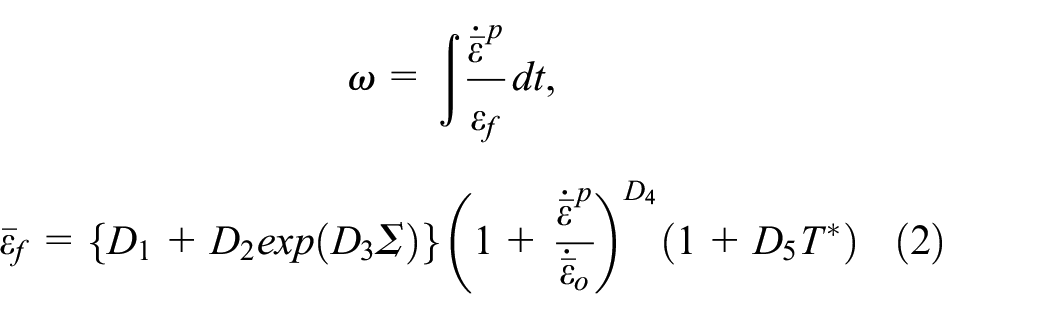
where dt is time step,
Parameters of Johnson-Cook damage model for C45 steel. 19

Results and discussion
Chip formation
Figure 3 shows the chip formation after the turning process for C45 steel at a cutting speed of 0.46 m/s and different cutting depths in both the experiment and simulation. In general, there is a fairly good agreement between the computational and experimental results regarding chip formation. Specifically, at a cutting speed of 0.46 m/s, the chips exhibited a long and tubular continuous morphology at low cutting depth of 0.5 mm. In this case, the length and thickness of the chip were around 90÷100 mm and 0.2 mm, respectively. As the cutting depth increased to 1 or 2 mm, the chips broke into short helical shapes with the length of 3÷5 mm and thickness of 0.4÷0.6 mm. In the case of a large cutting depth of 5 mm, the chip morphology exhibited a long helical shape of 80÷100 mm in length and 0.8 mm in thickness. These results suggest that cutting depth has a significant influence on chip morphology during the turning process for C45 steel.
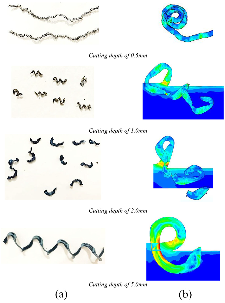
Chip formation at cutting speed of 0.46 m/s and different cases of cutting depth: (a) experiment and (b) simulation.
The influence of cutting speed on chip formation at a cutting depth of 1 mm in both the experiment and simulation is shown in Figure 4. When the cutting depth is 1 mm, short helical chips can be observed in all three cases of cutting speeds. The experimental results indicate that the higher cutting speed of 0.71 m/s tends to produce longer helical chips compared to the two cases of lower speed. This phenomenon is also observed in the computational results. Figures 3 and 4 support the validity of the simulation results.

Chip formation at cutting depth of 1 mm for different cases of cutting speed: (a) experiment and (b) simulation.
Figure 5 shows the experimental results for chip morphology at a cutting depth of 1 mm and a cutting speed of 0.46 m/s, captured at high magnification using a metallographic microscope OLYMPUS GX41 at different positions on the outer edges of the chip. At this high magnification, large cracks in the chip can be observed at both outer edges.
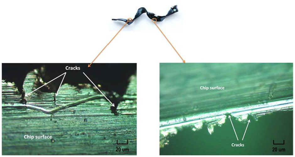
Chip observation in the case of 1 mm cutting depth and 0.46 m/s cutting speed.
Figure 6 presents the formation of cracks in the chip, along with the distribution of the damage variable at different displacements of the cutting tool in the case with a cutting depth of 1 mm and a cutting speed of 0.46 m/s, as obtained from the simulation. As seen in this figure, the initial crack appears at the left edge of the chip. Subsequently, another crack develops in the region where the damage variable reaches a sufficient value, appearing at the right edge of the chip. As a result, fractures may be induced on both sides of the chip, leading to the formation of short helical chips, as observed in Figure 4. This phenomenon closely resembles the experimental observations in Figure 5.

Distribution of damage variable at different displacements of tool at 1 mm cutting depth and 0.46 m/s cutting speed: (a) displacement of cutting tool of 5 mm and (b) displacement of cutting tool of 7 mm.
Thermal characteristics and machine learning prediction model
Thermal characteristics
Figure 7 shows the simulation results for the distribution of temperature on the workpiece, cutting tool, and chip at a cutting length of 20 mm for a cutting speed of 0.46 m/s and a cutting depth of 2 mm. The computational results indicate that the temperature on the nose of the cutting tool reaches a maximum value of 213°C. A non-uniform distribution of temperature is observed on the chip, with a maximum temperature of about 69°C at the interface between the chip and the cutting tool. This result can be attributed to the frictional heating phenomenon between the cutting tool and the newly formed chip surface. In other regions of the chip, the temperature is approximately 30°C. Additionally, the temperature generated on the surface of the machined part is quite low for the cutting speed of 0.46 m/s and cutting depth of 2 mm.

Simulation results on the distribution of temperature (a) on the parts of turning model and (b) on the chip at 20 mm cutting length (at 0.46 m/s cutting speed and 2 mm cutting depth).
From Figure 7, the highest temperature is distributed on the nose of the cutting tool. However, it is quite difficult to measure the temperature of the turning insert nose during the experiment; therefore, the temperature can only be measured near the turning insert nose at the position shown in Figure 1(b). As described in Section “Experimental setup,” the TK62 model thermocouple was used to capture the value of the temperature near the turning insert nose during cutting process. Figure 8 displays the temperature measured near the turning insert nose during cutting over a cutting length of 20 mm at different cutting depths and a cutting speed of 0.46 m/s. It can be seen that the temperature of the turning insert nose increases steadily during turning for all investigated cutting depths. Notably, the temperature rise correlates with an increase in cutting depth. At a small cutting depth of 0.5 mm, the temperature increases by only about 10°C after a cutting length of 20 mm. In contrast, with a cutting depth of 5 mm, the temperature near the cutting insert nose increases by about 50°C. An insignificant difference in temperature rise can be observed at cutting depths of 1 and 2 mm. These two cases show a similar trend in temperature rise, with each case indicating an increase of about 20°C after the investigated turning length.

Temperature values near the turning insert nose during turning at different cutting depths and cutting speed of 0.46 m/s in experiment.
The experimental results of the temperature near the turning insert nose during machining are shown in Figure 9 for different cutting speeds and a cutting depth of 2 mm after a cutting length of 20 mm. An increase in temperature during cutting is observed in all cases of investigated cutting speed. When the cutting speed is low, at 0.31 m/s, the temperature rise is the lowest, at only about 20°C. In contrast, the cases of higher cutting speeds, at 0.46 and 0.71 m/s, show higher rates of temperature rise.

Temperature near turning insert nose during the cutting at different cutting speed and cutting depth of 2 mm in experiment.
The distribution of temperature on the cutting tool at a cutting length of 20 mm in the simulation is presented in Figure 10. The temperature distribution is concentrated at the cutting tool nose, where the cutting tool directly contacts the chip in various cases of cutting depth and cutting speed. The effect of cutting depth on the temperature rise of the cutting tool nose is more pronounced than the effect of cutting speed. This result is consistent with the observations in the experiments shown in Figures 8 and 9. The temperature of the cutting tool nose at a cutting depth of 0.15 mm and a cutting speed of 0.31 m/s increases by only about 25°C after a cutting length of 20 mm. In contrast, at a higher cutting depth of 1 mm and a cutting speed of 0.71 m/s, the temperature of the cutting tool nose exceeds 200°C, while the temperature near the cutting tool nose reaches over 100°C. These temperature rise results from the simulation closely resemble those obtained from the experiments in Figures 8 and 9. The significant increase in temperature at the cutting tool nose is likely to affect the mechanical properties of the cutting tool material, which may considerably influence productivity, machining quality, and tool life.

Distribution of temperature on the cutting tool at cutting length of 20 mm in simulation.
Machine learning prediction model
In the present study, ANN technique was chosen over other machine learning techniques (e.g. linear regression, support vector machines) for temperature prediction. ANN was chosen because its flexibility, robustness, and capability to model nonlinear relationships of machining processes.21,22 It should be noticed that the relationship between machining parameters (cutting speed, depth, feed rate) and temperature is highly nonlinear due to interactions between material deformation, heat generation, and tool-workpiece friction. ANN can effectively adjust the weights and biases in its layered architecture to capture these nonlinearities.
An artificial neural network (ANN) is a machine learning approach inspired by the way biological neural systems process information. It consists of numerous interconnected elements, known as neurons, which are linked by weighted connections and work together to solve specific problems. 29 ANNs are tailored for various applications, such as regression, pattern recognition, or data classification, by learning from a set of training patterns. Typically, the structure of an ANN includes layers of neurons for input data, output data, and one or more hidden layers. 30 The widely used mathematical algorithm for optimizing ANN performance is the backpropagation algorithm. This algorithm adjusts the network by inputting a set of values, calculating the output, and comparing it to the actual measured value. If discrepancies are found, the weights are modified during backpropagation to minimize the difference. 31
Using the dataset shown in Figures 8 and 9, consisting of 80 data points, the data was divided into training, validation, and testing sets, comprising 70%, 15%, and 15% of the total, respectively. 70% provides a sufficient number of data points for the model to adjust its weights and bias without overfitting or underfitting. 32 A 15% allocation balances the need for enough data to evaluate the model effectively while preserving sufficient data for training. By allocating 15%, the testing dataset remains representative of the overall data distribution, providing reliable insights into actual performance.
The architecture of ANN model in the present study is depicted in Figure 11. The ANN model was trained with a single hidden layer containing 10 neurons. The backpropagation network utilized sigmoid-like neurons in the hidden layer, while the output layer used neurons with a linear transfer function. Figure 12 presents the cost function evaluation during the training process for the training, validation, and testing sets. It is important to note that the testing set was completely new to the model during testing. As shown in Figure 12, the mean square error (MSE) for the testing set displayed a favorable trend. The optimal iteration occurred at 43, where the MSE for the testing set began to increase. 33 This final configuration was saved for further performance analysis in subsequent sections.

Architecture of ANN model in the present study.
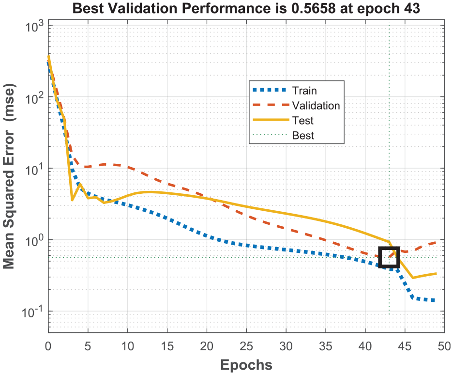
Evaluation of cost function during training. The optimal epoch was 43.
Figure 13 displays the regression graphs comparing the actual and predicted average temperatures near the turning insert nose for the training, testing, and overall datasets. The data points are distributed evenly around the diagonal line, indicating that overfitting was avoided during the training process. As summarized in Figure 13, the correlation coefficient (R) values are 0.9986, 0.9941, 0.9973, and 0.9981 for the training, validation, testing, and overall datasets, respectively. These results demonstrate a strong correlation between the predicted and actual data points.
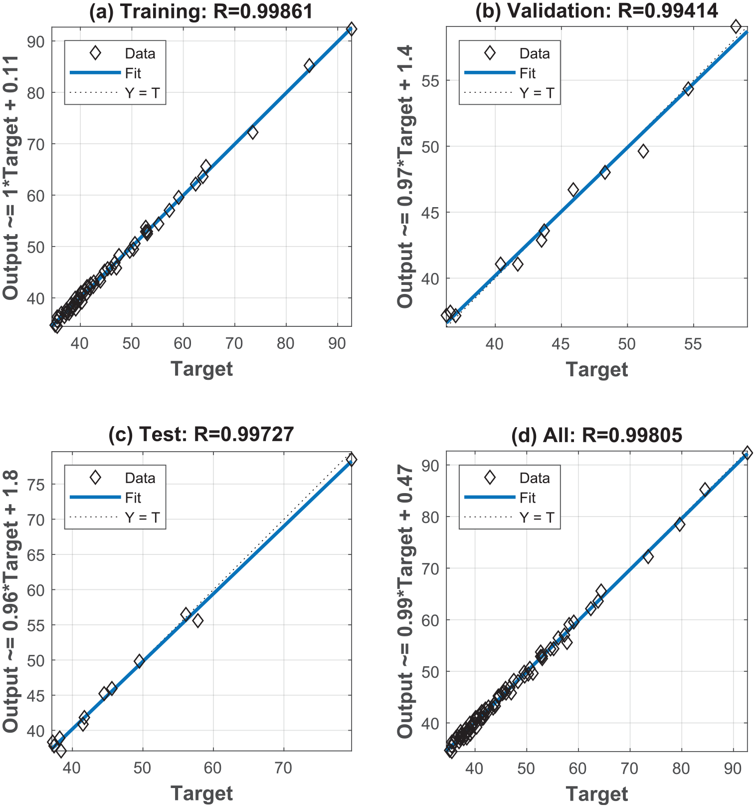
Comparison between actual and predicted data in regression scatter mode for (a) training data, (b) validating data, (c) testing data, and (d) all data.
The developed ANN accurately predicts temperature, therefore minimizing temperature-induced defects. 22 The developed ANN complements FEM simulations, which are computationally intensive, by providing faster predictions of temperature under varying conditions. 24 This hybrid approach enhances the reliability of simulations while saving computational resources.
Mechanical characteristics
Figure 14 shows the simulation results for the stress distribution on the chip and the machined surface of the workpiece at different cutting speeds and a cutting depth of 1 mm. A similar phenomenon in stress distribution is observed across the different cutting speeds. The maximum stress value is located in the chip-forming region, where the material separates from the workpiece. Meanwhile, the stress value on the machined surface is much smaller. Notably, the stress distribution on the machined surface at a cutting speed of 0.46 m/s is considerably lower than that at the two other cutting speeds of 0.31 and 0.71 m/s. According to Peng et al., 34 the presence of stress on the machined surface is considered residual stress, which may affect the quality of the machined surface. The machined surfaces at cutting speeds of 0.31 and 0.71 m/s exhibit noticeable roughness, leading to a poor surface finish. This result may be attributed to the built-up edge phenomenon caused by unsuitable cutting parameters.

Distribution of stress at cutting depth of 1 mm and different cutting speeds on (a) the chip and (b) the machined surface.
To examine the quality of the machined part, the distribution of plastic strain on the surface finish requires more attention than that on the chip, as a large value of plastic strain may lead to increased surface roughness and reduced surface quality. Figure 15 shows the distribution of equivalent plastic strain at a cutting depth of 1 mm and different cutting speeds obtained from finite element simulation. Higher values of plastic strain are observed at cutting speeds of 0.31 and 0.71 m/s compared to the case of 0.46 m/s. This result is consistent with the observations regarding the stress distribution shown in Figure 14. From Figures 14 and 15, it can be concluded that among the investigated cutting speeds, the turning process with a cutting speed of 0.46 m/s may be more suitable for C45 steel with a cutting depth of 1 mm.

Distribution of equivalent plastic strain at different cutting speeds.
Conclusion
In this study, the influence of machining parameters in the turning process of C45 medium carbon steel is examined through experimental investigation and finite element simulation using a two-dimensional model. The Johnson-Cook plasticity model and the Johnson-Cook damage model are applied to the workpiece material. The validity of the computation is confirmed by comparing the simulation results with experimental results regarding chip morphology and temperature rise during cutting. Several concluding remarks can be derived from the obtained results as follows:
The cutting depth significantly affects chip morphology in turning C45 steel. A small cutting depth typically produces long, tubular continuous chips. In cases with a medium cutting depth, the chips may break and form short helical shapes. In contrast, long helical chips are achieved at larger cutting depths. Additionally, cutting speed has a slight effect on the length of the formed chips when the cutting depth is 1 mm.
The temperature rise during the turning of C45 steel is much greater at the cutting tool nose than on the chip and the machined surface. In addition, as the cutting depth increases, the temperature of the cutting tool tip rises remarkably. The increase in cutting speed also significantly affects the rise in temperature of the cutting tool nose.
The case with a cutting speed of 0.46 m/s shows lower values of stress and plastic strain on the machined surface compared to the cases with cutting speeds of 0.31 and 0.71 m/s. Furthermore, roughness is induced on the machined surface at cutting speeds of 0.31 and 0.71 m/s due to the built-up edge phenomenon, leading to a poor surface finish. Among the investigated cutting speeds, the turning process with a cutting speed of 0.46 m/s may be more suitable for C45 steel with a cutting depth of 1 mm.
An effective machine learning based artificial neural network model is developed to predict the average temperature near the turning insert nose (the values of correlation coefficient R are 0.9986, 0.9941, 0.9973, and 0.9981, for the training, validating, testing, and all datasets, respectively).
Future research could focus on the machining performance of different grades of steel or other materials, such as high-strength alloys, composites, or non-ferrous metals. Investigating how varying material properties influence chip formation, temperature rise, and surface finish can contribute to the development of more universal machining strategies applicable to a broader range of materials. Last but not least, a larger database should be produced in order to apply efficient machine learning model, and to develop empirical prediction equation.
Footnotes
Handling Editor: Zuzana Murčinková
Author contributions
Tien-Thinh Le: Methodology, Writing – original draft preparation, Writing – review and editing; Hang Thi Pham: Conceptualization, Methodology, Formal analysis and investigation, Writing – original draft preparation; Hiep Khac Doan: Data curation, Formal analysis and investigation, Validation; Panagiotis G. Asteris: Writing – review and editing, Supervision.
Declaration of conflicting interests
The author(s) declared no potential conflicts of interest with respect to the research, authorship, and/or publication of this article.
Funding
The author(s) received no financial support for the research, authorship, and/or publication of this article.
Informed consent
Informed consent was obtained from all individual participants included in the study.
Data availability
Data available on request from the authors.