
Abstract
Journal bearings can suffer damage and reduced performance due to misalignment and impact loads, potentially leading to operational failures. This study addresses the issue by integrating a groove-type flexible structure and rubber into the bearing design to enhance lubrication characteristics under such conditions. The research evaluated various factors, including shaft center trajectory, minimum oil film thickness, maximum deformation, oil film pressure distribution, and deformation distribution under static and dynamic impact loads of varying magnitudes and directions. The results showed that the combination of the flexible structure and rubber significantly improved the lubrication characteristics, particularly under large impact loads and static load conditions. The use of rubber with a low elastic modulus alongside the flexible structure resulted in at least five times increase in the minimum oil film thickness compared to using the flexible structure alone. This enhancement is due to the elastic deformation of the lubricating surface driven by oil film pressure, ensuring sufficient oil film thickness even under substantial impact loads. The findings suggest that this design approach can significantly contribute to stable lubrication in mechanical systems frequently subjected to impact loads, thereby improving their reliability and operational performance. These numerical results are expected to significantly aid in maintaining stable lubrication in mechanical systems that frequently experience impact loads, thereby enhancing their reliability and performance.
Keywords
Introduction
Journal bearings are essential components in rotating machinery and are susceptible to various issues that necessitate quick detection. They typically consist of a fixed cylindrical bearing housing through which the shaft rotates at a predetermined velocity. Lubrication is supplied in the gap between the shaft and the bearing surface, facilitating smooth operation through hydrodynamic pressure produced by the oil film.1–4 Whirl instability can manifest during the operation of journal bearings due to multiple factors. Consequently, wear occurs due to direct metal-to-metal contact 5 between the shaft and bearing, potentially causing the mechanical system to halt or sustain damage. When operated with high eccentricity due to excessive specific pressure, journal bearings may undergo elastic deformation and experience a rise in temperature. 6 Shaft misalignment significantly impacts the lubrication performance of journal bearings. Even slight misalignment can lead to considerable variations in temperature distribution.7–14 Bearing failures, including those in journal bearings, generally produce abnormal vibrations, decrease equipment accuracy and efficiency, shorten the lifespan of components, and can lead to catastrophic accidents. 15 This study evaluates the effects of static and various impact loads in the state of misalignment among the causes of bearing failure. Research has been conducted on impact loads in various bearings such as oil bearings,16–19 air foil bearings,20,21 and water-lubricated bearings. 22 It has been demonstrated that when the amplitude of random impact loads is significant, the average lifespan of the bearing decreases. 16 Studies have also shown that air foil bearings perform well in terms of rotor stability and vibration under diverse shock load conditions. 20 Moreover, double bladder structures have enhanced the stability of water-lubricated bearings under half-sine impact load conditions. 22 Additionally, studies have involved the application of profiles23,24 or flexible structures25–29 in design to enhance lubrication characteristics in misaligned journal bearings.
Specifically, the application of groove-shaped flexible structures to misaligned journal bearings has demonstrated improved lubrication characteristics under static loading conditions, 25 as well as under both static and impact loads in the gravitational direction. 28 However, an analysis is lacking for scenarios where impact loads of differing directions from the static load are applied to misaligned journal bearings with flexible structures, and no corresponding design proposal has yet been presented. Given that impact loads can occur in various directions, it is crucial to develop a design strategy to enhance lubrication characteristics under diverse impact load conditions.
In this study, the groove-shaped flexible structure along with the inclusion of rubber aims to enhance the lubrication performance in misaligned journal bearings. Rubber, which is capable of elastically deforming under load, thus absorbing shock and preventing material damage, is utilized.30,31 Leveraging the benefits of rubber and the flexible structure, this study endeavored to enhance the performance of journal bearings by incorporating a flexible structure and rubber at the bearing’s end under various impact load conditions. The utilization of rubber is differentiated into instances where it is inserted between the groove area and the lubricant area, and where it is placed within the groove itself. Lubrication characteristics were evaluated by comparing the minimum oil film thickness, maximum deformation, and axial trajectory.
Numerical model and methods
In this study, an elasto-hydrodynamic lubrication (EHL) analysis was performed to evaluate the elastic deformation of the journal bearing end induced by oil film pressure. Specifically, this analysis aimed to account for the groove-shaped flexible structure applied at both ends of the bearing and the deformation resulting from the insertion of rubber, thereby gaining insights into the lubrication characteristics.
Journal bearings were investigated under conditions that involved the application of an impact load alongside the static load imposed by the shaft weight. The loading conditions employed in the analysis are illustrated in Figure 1. Figure 1(a) indicates the directions of the static and impact loads. While the static load is oriented solely in the direction of gravity, the impact load includes two additional directions beyond gravity. Moreover, whereas the static load remains constant, the impact load is characterized by a sinusoidal attenuation. The impact load was examined in two scenarios: one where the maximum load matches the static load (1 W) and another where it is double the static load (2 W). In the analysis, simulations where the static and impact loads coincided were conducted. For instance, when the impact load’s maximum value is twice that of the static load, the total maximum load exerted on the bearing is three times the static load.

Load condition: (a) direction of static and impact load and (b) magnitude of static and impact loads with time.
An unsteady-state lubrication analysis was performed on a misaligned journal bearing using COMSOL Version 6.0, a commercial software designed for multi-physics analysis. This analysis utilized finite element analysis, and three distinct modules were employed. These included the hydrodynamic bearing module for analyzing the lubrication state supported by oil film pressure generated by shaft rotation, the solid mechanics module to account for elastic deformation of the bearing surface due to the oil film, and the solid-bearing coupling module to facilitate seamless integration and interaction between the hydrodynamic and solid mechanics modules.
Bearings become misaligned for a variety of reasons. At this juncture, metal-to-metal contact occurs between the shaft and the bearing at the bearing’s end, as depicted in Figure 2(a). A previous study23,26 implemented a groove-shaped flexible structure at one end of the bearing to avert metal-to-metal contact in misaligned journal bearings. This flexible structure is prone to elastic deformation under oil film pressure, facilitating metal contact.
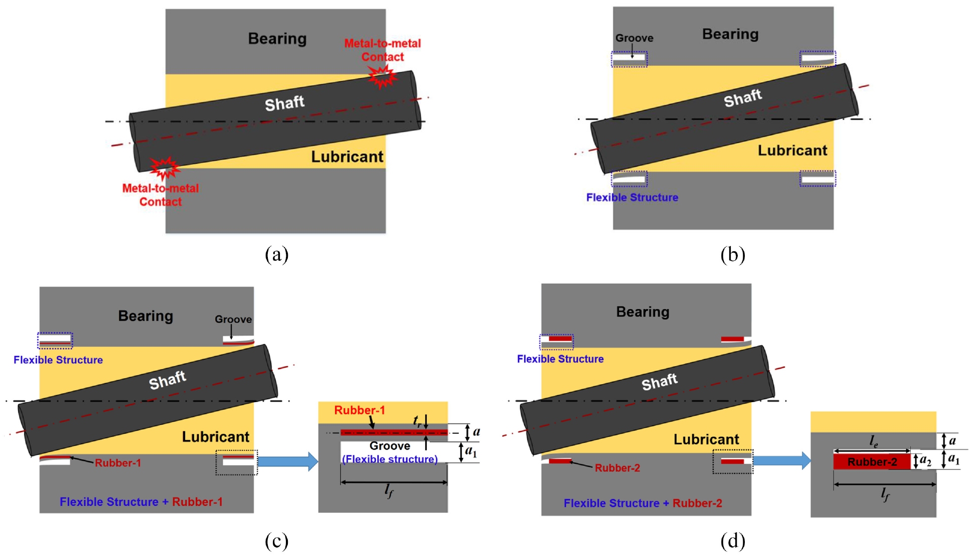
Misaligned journal bearing: (a) metal-to-metal contact, (b) application of flexible groove structure, (c) implementation of flexible groove structure and Rubber-1, and (d) implementation of flexible groove structure with Rubber-2.
In this study, a flexible structure was applied to both ends of the bearing to accommodate impact load conditions in various directions, as illustrated in Figure 2(b). Additionally, rubber inserts were featured along with the flexible structure in Figure 2(c) and (d). Figure 2(c) depicts rubber inserted between the groove and lubricant areas (Rubber-1), and Figure 2(d) shows rubber within the groove area (Rubber-2). This configuration, which incorporates rubber along with the groove-shaped flexible structure, aims to enhance the effect of elastic deformation resulting from oil film pressure at the bearing ends. A no-slip contact boundary condition was established between the rubber and the bearing.
In Figure 2(c) and (d), the thickness between the groove area and the lubricant area is a, while the dimensions of the groove are: width lf and height a1. In Figure 2(c), Rubber-1, matching the groove’s width (lf), is inserted, with a thickness defined by tr. Meanwhile, in Figure 2(d), Rubber-2 has a width and thickness of le and a2, respectively.
In relation to the above-mentioned content, the dimensionless variables used in the analysis are presented in equation (1).

Reynolds’ method for unsteady state was used to perform hydrodynamic lubrication analysis as depicted in equation (2).
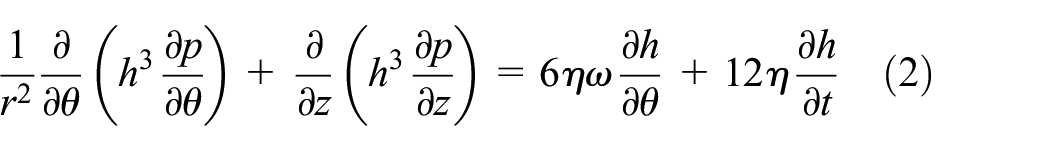
where r represents the bearing radius, p denotes oil film pressure, h signifies the oil film thickness, t is time, η indicates absolute viscosity, and z and θ are cylindrical coordinates, respectively.
when equation (2) is converted to a dimensionless equation, it is presented as equation (3).

where pa represents the atmospheric pressure, with the dimensionless variables specified in equation (4).

To calculate the oil film pressure (p) as outlined in equation (2), it is imperative to first ascertain the oil film thickness (h). Figure 3 illustrates the eccentricity and tilting motion of the shaft. The midpoint of the shaft, where z = l/2, is denoted as O, while O1 and O2 represent the centers at the ends of the shaft embedded within the bearing. In Figure 3(b), the two circles portray the cross-sections of the shaft on the x-y plane, centered at O1 and O2 respectively. Eccentricity, e, defines the displacement between centroid O and the center of the bearing aligned along the x-y plane. The angle ψ on the x-y plane signifies the altitude angle between the load direction and the line connecting O and the bearing center. Furthermore, the shaft’s tilting direction is designated by θw, while the tilting magnitude e′ represents half the distance between O1 and O2 on the x-y plane. 28

Position and forces of the shaft in the misaligned journal bearing displaying eccentric and tilted motion: (a) y-z plane, (b) x-y plane, and (c) forces resulting from oil film pressure.
Additionally, the groove of oil feeding is located at the top part of the bearing, as shown in Figure 3(c), and has a diameter of 10 mm.
When the shaft is aligned and exhibits no tilting, it rotates within the bearing. The oil film thickness between the shaft and the bearing is assessed using equation (5).

Upon transforming equation (5) into its dimensionless form, it yields equation (6).

where the dimensionless variables are as in equation (7). The parameters ε and ε′ appearing in equation (7) depict eccentricity and tilting ratio of the shaft, respectively.

Since the groove-type flexible structure is incorporated at the end of the bearing, both the elastic deformation of the bearing and the alteration in oil film thickness must be considered. Consequently, the elastic deformation calculated by the solid mechanics module influences the oil film thickness. Figure 4 illustrates the finite element analysis mesh in a cylindrical coordinate system. The study was conducted based on prior numerical analysis experience from previous research,25,28,29 which provided an approximate understanding of mesh independence. In this case, since rubber is inserted into the groove region, additional preliminary analyses were performed to ensure mesh independence. Specifically, to examine the influence of mesh on the groove region and the rubber-inserted area, we compared the minimum film thickness results by varying the number of mesh elements in both the circumferential and axial directions. When comparing 100 and 108 mesh elements in the circumferential direction, the change in minimum film thickness was less than 3%. For the axial direction, we applied 40, 52, and 60 mesh elements to reduce the total number of mesh elements. In the case of 40 axial mesh elements, the deformation in the groove region was not well captured. However, when 52 and 60 mesh elements were applied, the difference in analysis results was less than 1.6%. Therefore, the mesh for both the circumferential and axial directions was determined as follows. A hexagonal mesh is employed to improve convergence and accuracy. The analysis incorporates 100 elements in the circumferential direction and 52 elements in the axial direction, with the exclusion of the groove area, where 108 circumferential elements are utilized. The total number of elements is 558,240. Convergence criteria are established with a threshold of 10−3 for continuity, velocity, and deformation. Boundary conditions are essential for computing the Reynolds equation (equation (2)) to determine the oil film pressure, as specified in equation (8).
- In the oil film rupture area, the pressure was set to atmospheric pressure. The n indicates the direction perpendicular to the boundary line at the oil film fracture.
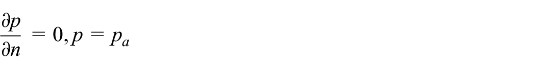
- The pressure in the cavitation area is established at atmospheric pressure.

- The pressure at the end of the bearing and the oil feeding groove are as specified.


Three-dimensional finite element analysis model in cylindrical coordinate.
When equation (8) is converted to dimensionless form, it is represented as equation (9).

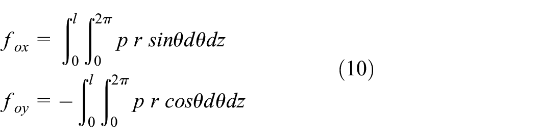
The oil film force, denoted as fo is generated by the pressure within the oil film and is used to assess the shaft’s motion by comparing it with the applied load. Figure 3(c) illustrates the oil film force acting on the shaft. The components of this force in the x and y directions, represented as fox and foy respectively, are calculated using equations (10). The overall oil film force is determined using equation (11). 28

When equations (10) and (11) describing the oil film force are converted to dimensionless form, they become equations (12) and (13), respectively.


where the dimensionless variables correspond to those in equation (14).

The actual dimensions and material properties used in the analysis are as follows. The bearing radius and clearance are 100 and 0.1 mm, respectively, and the bearing material is bearing steel with a Young’s modulus of 287 GPa, a density of 7850 kg/m3, and a Poisson’s ratio of 0.3. The operating conditions include a rotational speed of 104 rad/s and an applied static load of 576 kN. The shaft tilt angle is 6.67 × 10⁻⁵ rad. The absolute viscosity and density of the lubricant used in the analysis are 0.0208 Pa s and 904 kg/m3, respectively.
Figure 5 shows the flowchart of the numerical analysis. The location of the shaft center, where the oil film force equals the load, is calculated iteratively. The variations in oil film pressure and elastic deformation interact with each other, and therefore, they are calculated iteratively for each shaft center location until the given convergence criteria are satisfied.

Flowchart for the numerical analysis.
Additionally, contact occurs between the rubber and the bearing material due to the deformation of the bearing. It was assumed that the rubber and the bearing were fully bonded, so no special boundary conditions were applied. Contact conditions were only applied when the rubber was included in the groove. To apply the contact conditions, a pair was defined between the boundary surfaces of the rubber and the groove. In this case, when significant deformation occurs in the groove and the distance between the rubber and the groove becomes zero, the contact condition is triggered. For the contact analysis, the Penalty method was used, selected from the three available methods: Penalty, Augmented Lagrangian, and Nitsche. Using the Penalty method ensures that the boundaries in the contact pair remain in contact after coming into contact.
Moreover, under the given operating conditions, the temperature of the lubricant and the contact surfaces within the clearance may rise due to viscous friction. Although the lubricant recirculation system is not explicitly represented in the analysis, most systems typically incorporate recirculating lubrication systems equipped with coolers or chillers for cooling. Therefore, it is reasonable to assume that the lubricant behaves as an isothermal fluid within the clearance, considering the cooling effect provided by the recirculation system.
Numerical results and discussion
In this study, a grooved flexible structure along with rubber was utilized to enhance the lubrication properties of misaligned journal bearings. Initially, the lubrication properties were assessed under conditions that involved both a vertical static load and impact loads from three directions on the grooved flexible structure. The impact loads administered ranged from being equal to the static load to twice its magnitude. The study was constrained to scenarios where both static and impact loads were applied concurrently. Previous studies25,28,29 have shown that the application of impact loads, along with static loads, on misaligned journal bearings typically resulted in metal-to-metal contact. However, this was not the case when the grooved flexible structure was integrated at the bearing’s end, preventing any contact between the bearing and the shaft. Figure 6 illustrates the dimensionless minimum film thickness under three directional impact loads while a constant static load is maintained along the gravity vector. The specific conditions utilized in this analysis are detailed in Table 1. The numerical analyses considered cases where the maximum impact load equaled the static load (1 W) and where it was doubled (2 W). Further, the dimensionless minimum film thickness was analyzed in relation to variations in A (a/r) among the design parameters of the flexible structure. Under identical loading conditions, an increase in A resulted in reduced dimensionless minimum film thickness. This observed reduction is attributable to the increased material thickness of the bearing between the lubricating oil zone and the flexible structure zone, which hinders deformation caused by oil film pressure. Conversely, at lower values of A, employing a flexible structure proves beneficial for harnessing the deformation of the lubricating surface under oil film pressure to maintain adequate film thickness. When A is held constant, the dimensionless minimum film thickness is notably thinner in situations where the maximum impact load is 2 W compared to those with a 1 W load. This outcome stems from the compounded influence of both the static and higher impact loads on the journal bearing, which consequently deteriorates the lubrication properties. Specifically, when the direction of the impact load aligns with gravity (indicated in black), the resulting dimensionless minimum film thickness is smaller than in other directions due to the concurrence of static load direction with that of the impact load, further degrading the lubrication properties.

Dimensionless minimum film thickness with variation of load conditions and A.
Working conditions of numerical analysis (variation of A and load condition).

Figure 7 illustrates the variation in the dimensionless minimum film thickness over time for A values of 0.1 and 0.3, with maximum impact loads of 1 and 2 W. The results from Figure 6 delineate the smallest dimensionless film thickness across the entire time domain, as detailed in Figure 6. When comparing Figure 7(a) and (b), it can be observed that under identical A conditions, the dimensionless minimum film thickness tends to be lower when subjected to larger maximum impact loads. This suggests a deterioration in the lubrication characteristics of the journal bearing as the impact load magnitude increases. The variation in the dimensionless minimum film thickness with changes in dimensionless time remains consistent across different impact load magnitudes. Specifically, Figure 7(a) and (c), as well as Figure 7(b) and (d), display similar patterns in results. Figure 7(e) and (f) illustrate the variations in dimensionless minimum film thickness when the direction of the impact load is π and π/4, with varying values of A. In areas where the minimum film thickness is relatively larger (indicating an upward trend), the results exhibit minimal differences. However, in areas where the minimum film thickness is reduced, the discrepancy in results becomes markedly more noticeable. Particularly, when the direction of the impact load aligns with the direction of gravity (π), the variation in dimensionless minimum film thickness becomes more significant. Figure 8 presents the dimensionless maximum deformation over dimensionless time for A values of 0.1 and 0.3, under maximum impact loads of 1 and 2 W. Here, the dimensionless maximum deformation, which occurs in the flexible structure, resembles a damped sine wave that echoes the pattern of the impact load. Moreover, an increase in the maximum impact load corresponds to an increase in dimensionless maximum deformation. When A is large, the maximum elastic deformation in the flexible structure appears to be relatively smaller. This reduction can be attributed to the increased thickness of the bearing between the lubricating oil region and the flexible structure region, which renders deformation from oil film pressure more challenging. Figure 8(e) and (f) detail the differences in dimensionless maximum deformation when the direction of the impact load varies between π and π/1.6, across different A values. As demonstrated in Figure 8(f), when the maximum impact load is substantial, the disparity in maximum deformation due to the direction of the impact load also becomes more discernible. Furthermore, with higher values of A, the dimensionless maximum deformation tends to be relatively smaller. In summary, Figure 7(e) and (f) reveal that the fluctuation in minimum film thickness over time is significantly influenced by the direction of the impact load. Conversely, Figure 8(e) and (f) highlight how the magnitude of maximum deformation is substantially impacted by A within the flexible structure. Thus, under the analytical conditions for journal bearings, minimum film thickness is predominantly affected by loading conditions such as impact load, whereas maximum deformation is profoundly influenced by the parameter A in the flexible structure.
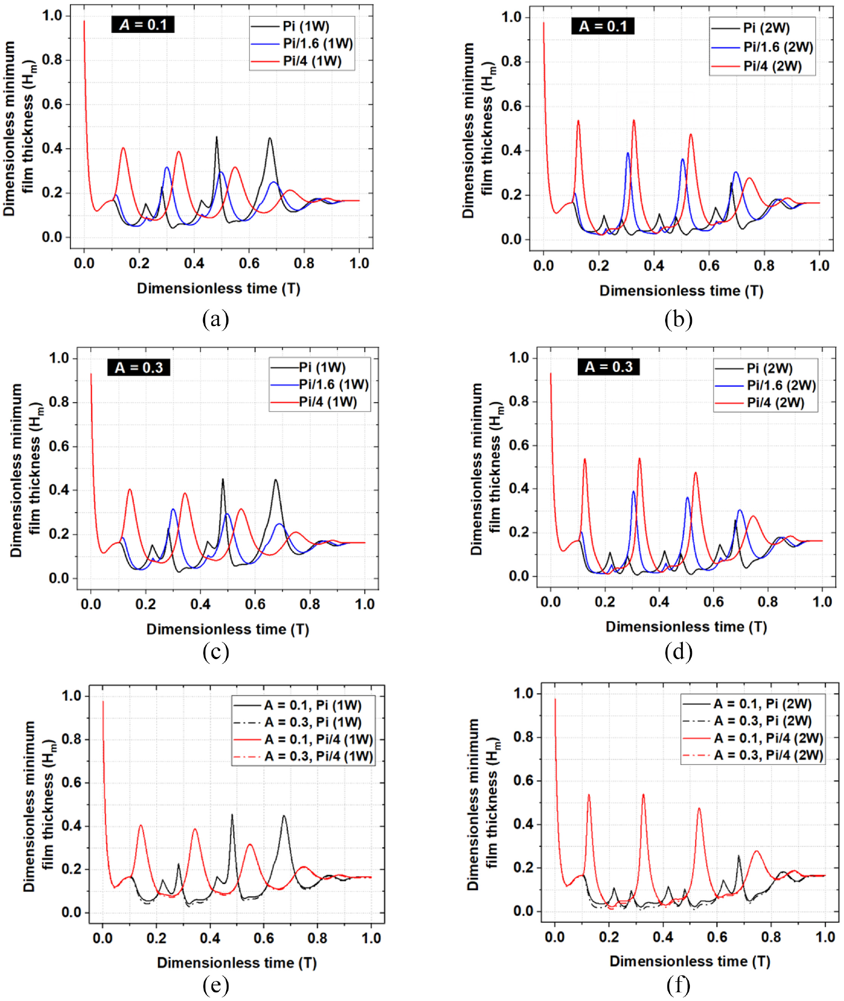
Dimensionless minimum film thickness with dimensionless time under varying load conditions and A: (a) A = 0.1, Wmax = 1 W, (b) A = 0.1, Wmax = 2 W, (c) A = 0.3, Wmax = 1 W, (d) A = 0.3, Wmax = 2 W, (e) A = 0.1, 0.3, Wmax = 1 W (π, π/4), and (f) A = 0.1, 0.3, Wmax = 2 W (π, π/4).
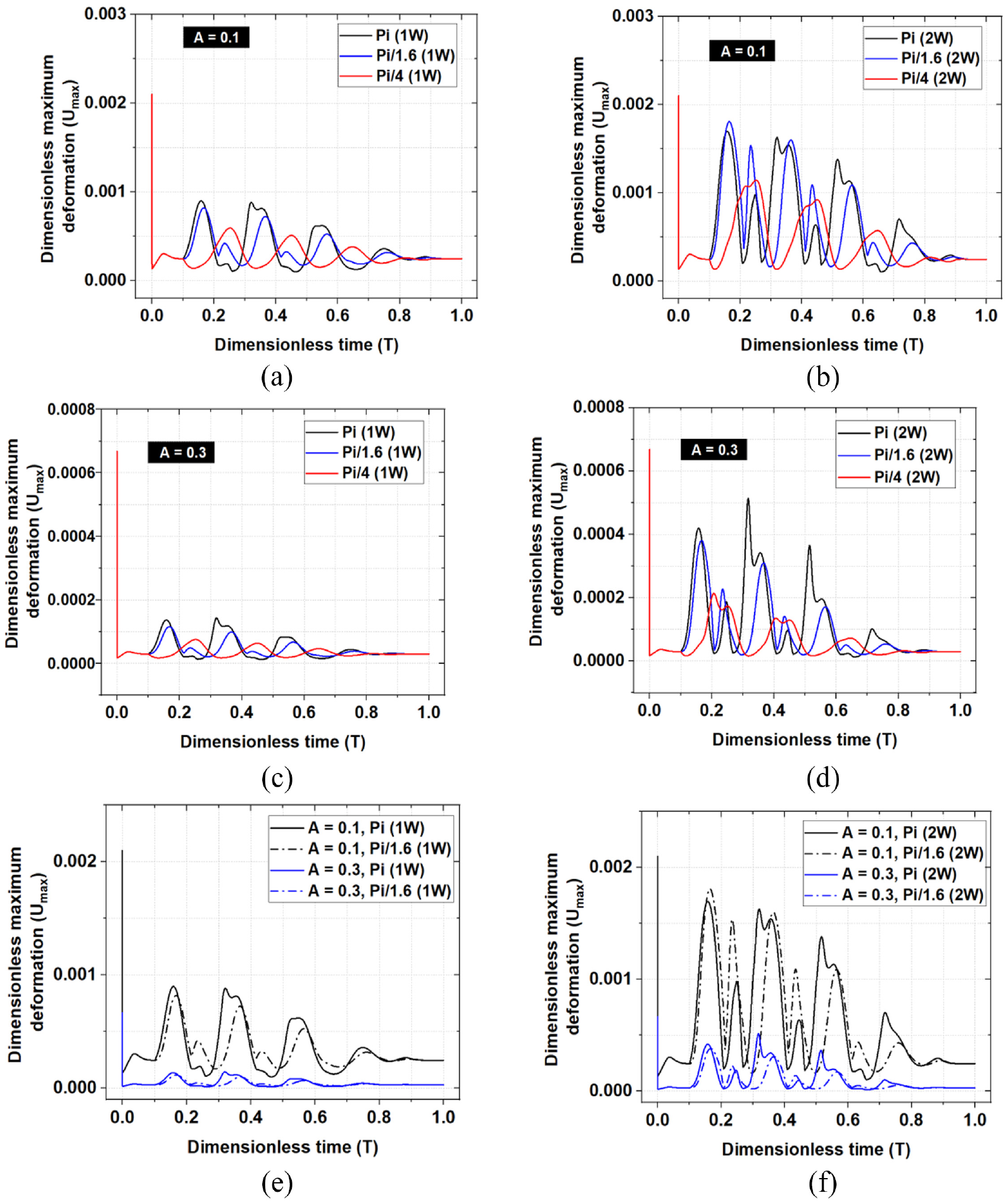
Dimensionless maximum deformation with dimensionless time in varying load conditions for parameter A: (a) A = 0.1, Wmax = 1 W, (b) A = 0.1, Wmax = 2 W, (c) A = 0.3, Wmax = 1 W, (d) A = 0.3, Wmax = 2 W, (e) A = 0.1, 0.3, Wmax = 1 W (θwi = π, π/1.6), and (f) A = 0.1, 0.3, Wmax = 2 W (θwi = π, π/1.6).
Next, the lubrication characteristics were investigated in misaligned journal bearings with variations in the dimensionless length (Lf) of the flexible structure and the tilting ratio (ε′).
Figure 9 presents the dimensionless minimum film thickness with variation of load condition and dimensionless length of the flexible structure. A constant static load was applied in the direction of gravity, while the impact load was applied in a damped sine wave form in three directions (π, π/1.6, π/4). As previously reported, analyses were conducted for conditions in which the maximum impact load was up to double that of the static load. This set of conditions is exemplified in Table 2. The findings indicate that as the dimensionless length of the flexible structure is increased, from 0.1 to 0.2, there is an increase in the dimensionless minimum film thickness. This suggests that increased Lf facilitates deformation due to oil film pressure and promotes a thicker film thickness.

Dimensionless minimum film thickness with variation of load conditions and Lf.
Working conditions of numerical analysis (variation of Lf and load condition).

Figure 10 illustrates the dimensionless minimum film thickness and dimensionless maximum deformation over dimensionless time for cases where Lf is 0.2, the maximum values of the impact load are 1 and 2 W, and the directions of the impact load are π and π/4. The dimensionless maximum deformation over dimensionless time closely mirrors the pattern of the applied impact load in the analysis. Characteristically, the impact load, a decaying sine wave, is mirrored by the behavior of the dimensionless maximum deformation. Moreover, in the region where the dimensionless minimum film thickness is minimal, the dimensionless elastic deformation is considerably large, signifying that stable lubrication can be maintained without metal-to-metal contact. This phenomenon becomes increasingly pronounced as the maximum value of the impact load increases.

Dimensionless minimum film thickness and dimensionless maximum deformation with dimensionless time (variation of load condition and Lf): (a) Lf = 0.2, Wmax = 1 W, θwi = π, (b) Lf = 0.2, Wmax = 1 W, θwi = π/4, (c) Lf = 0.2, Wmax = 2 W, θwi = π, and (d) Lf = 0.2, Wmax = 2 W, θwi = π/4.
Figure 11 depicts the dimensionless minimum film thickness with variation of load condition and tilting ratio (ε′). A constant static load was applied in the direction of gravity, while the impact load was delivered in a form of a damped sinusoidal wave in three directions (π, π/1.6, π/4). The settings used in this assessment are detailed in Table 3. As the tilting ratio rises, the decrease in dimensionless minimum film thickness is evident, indicating that an increase in shaft deviation from the bearing center correlates with declining lubrication conditions. Nevertheless, despite the increased tilting ratio and the presence of an impact load, it is confirmed that there is no contact due to the structure’s flexibility.

Dimensionless minimum film thickness with variation of load conditions and ε′.
Working conditions of numerical analysis (variation of ε′ and load condition).

Figure 12 illustrates the orbit of the shaft center, which varies based on the direction and maximum value of the impact load. When the direction of the impact load coincides with the static load, the orbit is notably wider. Moreover, a larger maximum impact load in the same direction results in a correspondingly wider orbit.

Orbit of the axis center with dimensionless time at ε′ = 0.05 (variation of load condition): (a) θwi = π, Wmax = 1 W, (b) θwi = π/1.6, Wmax = 1 W, (c) θwi = π/4, Wmax = 1 W, (d) θwi = π, Wmax = 2 W, (e) θwi = π/1.6, Wmax = 2 W, and (f) θwi = π/4, Wmax = 2 W.
The previous results related to scenarios where grooves were implemented at the bearing ends. In this phase of research, the focus shifts to examining the lubrication characteristics of the bearing when incorporating both grooves and rubber. As introduced earlier, two configurations were proposed: one involving the insertion of rubber (Rubber-1) between the lubricant zone and the groove zone of the bearing, and another incorporating rubber (Rubber-2) directly within the groove. Initially, we assessed the lubrication properties based on variations in the thickness and elastic modulus of the rubber positioned between the lubricant area and the groove zone.
In the analysis conducted, one particularly harsh working condition was imposed. This condition entailed severe tilting, with impact loads aligned with the static load, and the maximum magnitude of the impact load reaching twice that of the static load (2 W) as outlined in Table 4. The lubrication characteristics were examined comparing a scenario with only the existing flexible structure and another where both the flexible structure and rubber were implemented. The rubber, characterized by an elastic modulus ranging from 1 to 100 MPa, had specific values of 1, 10, and 100 MPa tested. The Poisson’s ratio of rubber is 0.5. Figure 13 illustrates the dimensionless minimum film thickness in scenarios employing only the flexible structure and those incorporating both the flexible structure and rubber. As previously mentioned in equation (1) and Figure 2, Lg represents the dimensionless thickness of the rubber insert (Rubber-1). The insertion depth of the rubber Lf was kept consistent with the depth of the groove (flexible structure). The brown star-shaped symbols in the figure depict the dimensionless minimum film thickness when only the flexible structure is implemented. As Lg increases, there is generally an increment in the overall dimensionless minimum film thickness. This results from the increment in rubber thickness that enhances film thickness due to elastic deformation under oil pressure. Furthermore, a lower dimensionless elastic modulus (ER*) of the rubber leads to easier elastic deformation of the lubricated surface under oil pressure, thus augmenting the minimum film thickness. According to the findings, utilizing rubber along with the flexible structure in the journal bearing significantly enhances the minimum film thickness—up to five times greater than using only the flexible structure. This significant improvement in lubrication characteristics under impact loads demonstrates the efficacy of rubber integration in misaligned journal bearings. Additionally, when ER* is 0.0763, the variation in minimum film thickness between Lg values of 0.4 and 0.5 is marginal. This is attributed to a point where Lg exceeds a threshold; beyond this, the effect of elastic deformation due to the lubricant pressure becomes negligible, even if the rubber’s elastic modulus (ER) is lower.
Working conditions of numerical analysis (application of Rubber-1).

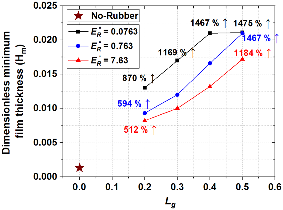
Dimensionless minimum film thickness as a function of the dimensionless elastic modulus of rubber and Lg.
Figure 14 illustrates the dimensionless minimum film thickness and dimensionless maximum deformation for conditions involving solely the flexible structure and for the condition combining the smallest elastic modulus of rubber with the flexible structure, as derived from the findings in Figure 13. These results clearly demonstrate that adding rubber to the flexible structure induces significantly enhanced elastic deformation compared to using the flexible structure alone. Consequently, this alteration leads to an expansion in the minimum film thickness due to increased oil pressure. In summary, the integration of a flexible structure with rubber enhances the elastic deformation of the lubricated surface, thereby ensuring sufficient film thickness for consistent lubrication.

Dimensionless minimum film thickness and dimensionless maximum deformation corresponding to dimensionless time (variation of Lg): (a) dimensionless minimum film thickness and (b) dimensionless maximum deformation.
Next, an analysis was conducted concerning the scenario in which rubber was inserted into the flexible structure. In this analysis, the width of the inserted rubber (le) and the height (a2) are represented by the dimensionless parameters Le and A1, respectively. The specific working conditions are detailed in Table 4. The width of the rubber inserted into the groove equates to two-thirds of the width of the flexible structure, and analyses were performed for rubber inserted at heights equivalent to 0.8, 0.9, and 0.999 times the height of the flexible structure. To distinguish it from previous analyses, this rubber configuration is designated as Rubber-2. Based on previous results indicating improved lubrication performance with rubbers having lower elastic moduli, the analysis focused solely on a rubber with a dimensionless elastic modulus of 0.0763. Figure 15 illustrates the variation in dimensionless minimum film thickness with changes in A1, showing that the improvement in lubrication characteristics is minimal compared to scenarios involving only the flexible structure. Additionally, an inset within Figure 15 displays the dimensionless deformation distribution at the point where A1 equals 0.999 and maximum deformation occurs. The analysis of the dimensionless deformation indicates minimal change, with the deformation magnitude of the inserted rubber almost matching that of the flexible structure. Consequently, it can be concluded that the insertion of rubber has a minimal impact on deformation.
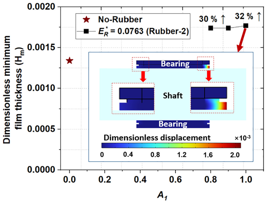
Dimensionless minimum film thickness with A1.
Thus far, my investigation has encompassed the lubrication characteristics of scenarios involving solely a flexible structure as well as configurations where rubber was incorporated. While previous studies have demonstrated the efficacy of enhancing lubrication by integrating a flexible structure in journal bearings, it was noted that as impact loads increase, surface contact occurs. To mitigate this, a design combining both a flexible structure and rubber insertion was suggested. Although integrating rubber exclusively within the flexible structure showed little effect on lubrication characteristics, placing rubber at the juncture between the lubrication zone and the flexible structure notably enhanced lubrication performance.
This study identifies a limitation in the practicality concerning rubber installation issues. From an implementation perspective, the use of adhesives for bonding rubber to metal or designing ways to ensure robust adhesion between these materials is necessary. Future experimental work is essential to address these challenges. This research is significant as it introduces innovative design solutions and underlines their practical implications in resolving these challenges.
Conclusions
This study endeavors to address the challenges associated with metal-to-metal contact and the subsequent failures induced by impact loads in misaligned journal bearings. To mitigate these issues, a groove-type flexible structure along with rubber inserts were strategically positioned at both ends of the bearing. The enhancement of lubrication characteristics under severe operating conditions, including misalignment, the exertion of static loads in the gravitational direction, and the application of impact loads from various orientations, was closely examined. Previous inquiries revealed that utilizing a flexible structure alone was inadequate to sustain stable lubrication under conditions of heavy impact loading. Consequently, this investigation proposes two remedial approaches: integrating rubber (Rubber-2) within the flexible structure, and situating rubber (Rubber-1) between the flexible structure and the lubricant zone within the bearing.
When rubber was incorporated within the flexible structure, the resulting elastic deformation of the lubricated surfaces, driven by oil film pressure, was minimal, leading to a marginal improvement in lubrication properties. Conversely, inserting rubber between the flexible structure and the lubricant zone resulted in a noteworthy enhancement in the lubrication characteristics of the journal bearing. Particularly, with the utilization of rubber possessing a lower elastic modulus, the minimal oil film thickness increased significantly, ranging from 5 to 14 times, which markedly improved the lubrication properties. This enhancement is attributed to the fact that the integration of rubber alongside the flexible structure facilitates the elastic deformation of the lubricating surface under oil film pressure, thus ensuring an adequate oil film thickness.
The findings of this study indicate that the application of this design in systems routinely subjected to impact loads or in machines at risk of failure due to misalignment could substantially improve the lubrication characteristics, thereby bolstering the reliability of the products. While the numerical research conducted thus far is promising, experimental studies are imperative for further validation, particularly in regards to the interface development between the rubber and metal components. Despite this, the present study is significant as it introduces an innovative approach that enables stable operation under harsh impact load conditions.
Footnotes
Appendix
Handling Editor: Michal Hajžman
Declaration of conflicting interests
The author(s) declared no potential conflicts of interest with respect to the research, authorship, and/or publication of this article.
Funding
The author(s) disclosed receipt of the following financial support for the research, authorship, and/or publication of this article: This work was supported by the Korea Hydro & Nuclear Power Co. (2023) and Korea Institute of Energy Technology Evaluation and Planning (KETEP) grant funded by the Korea government (MOTIE) (No.20214000000010).