
Abstract
Heavy equipment is often driven synchronously by multi-actuator hydraulic system. However, when the load deviation of the actuators is large, such systems exhibit serious energy loss and inferior synchronization performance. Inspired by the cluster flight of wild goose, a bionic hydraulic actuator and a bionic driving method are proposed. Different from traditional two-chamber hydraulic actuator, the redundant freedom of the bionic hydraulic actuator is used to simulate the airflow vortex formed by wild goose. By doing so, the bionic actuators can provide or accept auxiliary driving force from other actuators according to different topology. In addition, the optimal load balance performance of multi-actuators can be realized by adjusting the auxiliary driving pressure between actuators. In this study, topology switching rules and auxiliary pressure control strategies are discussed. Numerical simulation results demonstrate that the proposed method can reduce the maximum load deviation by over 85% and the synchronization error by over 80% in typical cases.
Keywords
Introduction
Heavy equipment often requires more than two actuators to drive synchronously, which puts forward higher requirements for the bearing capacity of the drive system and the coordination of multiple actuators. 1 Compared with other synchronization drive method, the multi-actuator hydraulic synchronization drive system has the advantages of large output force / torque, fast response speed and high stiffness. 2 It is widely used in industrial equipment and mining machinery such as hydraulic press, 3 hydraulic support, 4 casting machine, 5 shield tunneling machines. 6 These applications are usually characterized by load deviation, which means the load of each actuator varies greatly. This phenomenon often leads to significant differences of the dynamic characteristics of each actuator, thereby deteriorating the synchronization performance. Moreover, because the pump pressure can only match the maximum load pressure, another problem that cannot be ignored is the large energy consumption caused by load deviation. Therefore, both synchronization accuracy and system efficiency are affected by this problem. Up to now, there have been many studies concentrate on improving the synchronization performance under load deviation, and many advanced methods have been raised such as cross-coupling, 7 adaptive quasi-synchronization controller, 8 model predictive control. 9 However, above researches can do little on the reduction of energy consumption of this kind of system. Therefore, how to improve the efficiency and synchronization accuracy of multi-actuator hydraulic synchronization system simultaneously under load deviation remains to be solved, especially under the background of energy shortage and environmental pollution.
Although there is little research on energy saving of multi-actuator hydraulic synchronization system, the hydraulic energy-saving methods in application fields characterized by multi-actuator drive, such as construction machinery, can be used for reference 10 Positive flow control, negative flow control and load sensing are three typical energy-saving hydraulic systems widely used in construction machinery. The principle of positive flow control is that the output flow of the pump is positively correlated with the handle signals. In recent years, electro-hydraulic flow matching control with similar principle has been widely studied. 11 The principle of negative flow control is that the output flow of the pump is inversely proportional to the pilot pressure signal generated by the handle. According to this principle, we proposed an integrated energy saving and position tracking controller. 12 Theoretically, by using the above two methods, the pressure margin between the pump pressure and the maximum load pressure can be adjusted adaptively rather than set manually. Compared with the aforementioned two kinds of hydraulic systems, load sensing control and its improved form, namely electro-hydraulic load sensing, are more widely used in multi-actuator hydraulic system due to its anti-load-interference capability.13,14 To reasonably adjust the pressure margin instead of using a fixed value, variable supply pressure control is investigated to further improve the efficiency of load sensing system.15,16 In addition, in our previous research, a variable pressure control based on two hydraulic accumulators is proposed for the control of asymmetric hydraulic actuator. 17
Besides the aforementioned approaches, some unique methods are also used to improve the efficiency of multi-actuator hydraulic system. Independent metering control (IMC) is one of the hot-spots in recent years, such as Abuowda et al. 18 and Nguyen et al. 19 Another interesting research topic is the common pressure rail (CPR). This kind of system consists of high-pressure side and low-pressure side, which is similar to the electric grid system that has high and low voltage lines. 20 As a key component of CPR, hydraulic transformer can realize pressure regulation without throttling loss theoretically. Under the condition of large load deviation, the supply pressure is difficult to match all loads at the same time. Therefore, multi-source network hydraulic system with corresponding energy management strategy is developed to resolve this problem.10,21
The above methods can significantly improve the system efficiency by means of pressure adaptation. In other words, the essence of these methods is to dynamically change the supply pressure or use multiple power sources to adapt to load deviation rather than eliminating it. Because the maximum load pressure remains unchanged, the efficiency improvement is greatly limited. More importantly, for the multi-actuator hydraulic synchronization system, although the above methods can improve the system efficiency, they have no effect on the improvement of synchronization accuracy. It is necessary to propose a load balancing method so that the two aspects can both be taken into account. The cluster control of wild goose formation in nature can provide a new way to solve this problem. The wild goose often forms a neat “one-line” or “herringbone” queue when flying. By doing so, the wild goose in the team can save energy by using the “air flow vortex” caused by the front wild goose flapping their wings, and also provide vortex for the rear wild goose. Switching the formation topology according to different resistance conditions and adjusting the auxiliary force in real time can balance the load force of members and reduce the overall energy consumption. Inspired by this principle, a bionic hydraulic actuator is proposed. Based on this kind of bionic hydraulic actuator, load balancing of multi-actuator hydraulic synchronization system is achieved. To our best knowledge, this is the first time that the proposed bionic hydraulic actuator is used in the multi actuator synchronization system to realize the coordination and balance of multiple actuator loads.
The main contributions of this study can be summarized as follows
The proposed method can not only reduce the system energy consumption, but also ensures that the load of each actuator tends to be consistent, so as to improve the synchronization performance.
Different from the existing energy-saving approaches of multi-actuator hydraulic system, a bionic hydraulic actuator and a load balancing energy management method are proposed in this study to solve the load deviation problem and reduce the maximum load pressure fundamentally.
The topology switching rules and auxiliary drive pressure control strategy under different working conditions are developed. The effectiveness of the proposed method is validated by case studies.
The reminder of this paper is arranged as follows. Section “Basic working principle of the load balancing energy management method” introduces the basic working principle of the load balancing energy management method. The analysis of energy saving and dynamic characteristics of the system is discussed in Section “Analysis of energy saving and dynamic characteristics of the system .” The hydraulic topology of four actuator hydraulic synchronization system is given in Section “Discussion of hydraulic topology” and control strategy of auxiliary driving pressure is developed in Section “Control strategy of auxiliary driving pressure.” The proposed method is validated and analyzed in Section “Case study” and brief conclusions are drawn in Section “Conclusions.”
Basic working principle of the load balancing energy management method
Wild goose usually fly in groups based on a certain formation topology rather than alone. According to different resistance conditions, the formation topology can be switched to balance the resistance of team members. Through this mutual collaboration, the flying distance can be increased and the overall energy consumption can be reduced, which is shown in Figure 1. The elements of the topology include the relative relationship of providing or receiving auxiliary driving force between team members, driving form and the magnitude of auxiliary driving force.

Schematic diagram of flying principle and topology switching of wild geese formation.
There are many similarities between multi-actuator hydraulic synchronization and the above principle. Inspired by the above principle, a multi-actuator load balancing method based on bionic hydraulic actuators is proposed and the schematic diagram of bionic hydraulic actuator is shown in Figure 2. The bionic hydraulic actuator consists of a four-chamber hydraulic actuator, a switching valve (SV) and a proportional throttle valve (PTV). To simplify the description, the four-chamber hydraulic actuator is divided into a small asymmetric hydraulic actuator (auxiliary hydraulic actuator) and a large asymmetric hydraulic actuator (main hydraulic actuator), thus forming the green part of Figure 2. Since the main hydraulic actuator and auxiliary hydraulic actuator of four-chamber hydraulic actuator are an organic whole, when the main hydraulic actuator moves forward and backward, the auxiliary hydraulic actuator will also automatically follow. Assuming that the main hydraulic actuator of one driving unit (unit 1) moves to the left, the chamber 3 of corresponding auxiliary hydraulic actuator can provide pressure oil. In this case, if the chamber 3 is connected to the chamber 4 of another driving unit (unit 2) through the SV, the load forces of the two main hydraulic actuators can be indirectly adjusted by controlling the PTV. (because the flow of chamber 3 is greater than that of chamber 4, a part of the flow must pass through the PTV) Assuming that the main hydraulic actuator of driving unit 1 moves to the right, the chamber 4 of auxiliary hydraulic actuator can generate pressure oil. However, due to the flow of chamber 4 is not enough to enter chamber 3 of driving unit 2 to provide auxiliary driving pressure, so the driving unit 2 can be changed to differential driving mode through its SV, thereby achieving auxiliary drive. It can be inferred from the above working principle that the main hydraulic actuator is similar to the wild goose in the formation, while the passive energy supply of the auxiliary hydraulic actuator is similar to the “airflow vortex” formed by wild goose during flight. In addition, the topology is composed of three elements: magnitude, driving relationship and driving form of auxiliary driving force. (The first element is controlled by the PTV, and the last two elements are controlled by the SV).

Schematic diagram of the proposed bionic hydraulic actuator.
In this study, a typical four-actuator hydraulic synchronization system is designed and analyzed, so as to simulate the actual effect of the proposed system. The hydraulic actuator in the system adopts bionic hydraulic actuator instead of the traditional two chamber hydraulic actuator. The parameters of each bionic hydraulic actuators are the same, whereas the load forces of the four hydraulic actuators are different and time-varying. The ports A and B are the connecting ports of the main hydraulic actuator, while ports C and D are the connecting ports of the auxiliary hydraulic actuator. A typical topology is demonstrated in the lower part of Figure 3 (the direction of auxiliary driving force is from unit N to unit N-1.. to unit 1). It can be seen from the figure that the driving relationship (disconnect, provide or accept auxiliary force), drive form (direct drive or differential drive) and driving force between two adjacent drive units can be changed by switching the SV and controlling the PTV. These three elements can form different topology. According to the load of each actuator and taking the same load force of the main hydraulic actuator as the target, the analysis and calculation can be carried out, and then the control pressure of each PTV under a specific topology can be known. After using simple synchronization elements or algorithms to achieve basic synchronization, the load balancing method proposed in this project can make the driving characteristics of each drive shaft consistent, thus greatly improving the synchronization performance of multiple actuators (synchronization accuracy and system energy efficiency).

A typical Synchronous drive configuration based on bionic hydraulic actuator.
Figure 4 shows the possible auxiliary driving forms of two actuators (the PTV that does not have control function when the valve port is fully open is omitted). During the actuator retraction phase (as shown in the first figure), Unit 1 can provide auxiliary driving force to Unit 2 through SV switching and PTV control. Similarly, by switching SV reasonably, Unit 2 can also provide driving force for Unit 1. During the actuator extension phase (as shown in the second and third figures), Unit 1 or 2 can provide auxiliary driving force to another unit through differential connection (as shown in the second figure), or both can simultaneously increase auxiliary driving force (as shown in the third figure). Therefore, when there are multiple actuators, multiple different auxiliary driving forms or topological structures will be formed, which will be elaborated in detail in the following text.

Possible auxiliary drive forms for two actuators.
Analysis of energy saving and dynamic characteristics of the system
After introducing the basic principle of the proposed system, the advantages of load balancing in energy efficiency and accuracy of multi-actuator synchronous system should be discussed. The traditional hydraulic actuator usually has two chambers, namely piston chamber and rod chamber. Although the structure of this kind of actuator is simple and reliable, the interaction between actuators cannot be established by using traditional hydraulic actuators. This also means that multiple traditional actuators cannot achieve coordinate operation when moving synchronously. It is well known that large load deviation is common in hydraulic synchronization equipment such as hydraulic support and hydraulic hoist. Because the pump pressure can only match the maximum load pressure, it will result in serious energy consumption. Moreover, it can be seen from Figure 5 that the increase of the hydraulic actuator and load deviation will significantly increase the energy loss. The energy consumption of a hydraulic synchronization system with a load sensing variable displacement pump can be given as

where

Energy saving principle of the load balancing method.
It is assumed that the synchronization system exhibits ideal synchronization performance, that is, the load flow of each driving unit is the same, namely

where
It can be found from Eq. (2) that although advanced energy-saving method, such as load sensing and flow matching, can reduce the pressure loss between pump and actuator, namely
Large pressure difference not only reduces the system efficiency, but also makes the dynamic characteristics of each driving unit significantly different. Figure 6 shows the results of frequency domain analysis of a closed-loop synchronization system. It can be seen from Figure 6 that the bandwidth of the system decreases with the increase of load force or load pressure. Therefore, when the load of each actuator varies greatly, advanced control algorithms such as cross coupling need to be used to achieve accurate synchronization. However, due to the inconsistent driving characteristics of each driving unit, the design and parameter adjustment of the controller will be very complex.

Frequency domain analysis with different loads.
Discussion of hydraulic topology
As mentioned above, the topology is composed of three elements: magnitude, driving relationship and driving form of auxiliary driving force. Therefore, the topology of the four-actuator hydraulic synchronous system is analyzed as follows according to the three elements. Since the auxiliary driving force is realized by controlling the auxiliary driving pressure of the PTV, the desired auxiliary driving pressure under each topology is analyzed instead of the desired driving force.
Remark 1: In this study, the direction of the load force is always assumed to the left (as shown in Figure 3). The working condition where the load force is to the right can be derived from the derivation in this paper.
Driving relationship and driving form
Under different resistance and movement direction, the wild goose will flexibly change the formation according to the individual differences such as the physical strength of the formation members. For example, when the head wild goose is tired due to long-term flight, it will go to the tail of the team to preserve its physical strength. For the proposed hydraulic system, how to find the best topology to minimize load deviation and energy consumption needs to be further discussed.
For the four-actuator hydraulic synchronization system shown in Figure 3, the possible hydraulic topology are shown in Figure 7. The number in the blue circle represents the physical order of the driving unit, and the direction of the arrow represents the direction in which the auxiliary driving force is provided. Each driving unit can only interact with adjacent driving unit due to physical connection restrictions. There is no auxiliary driving force between the two drive units without arrow connection, and the PTV in the corresponding hydraulic circuit is fully open.

Possible hydraulic topological structures in different motion directions.
As shown in Figure 4, when the hydraulic actuator is in the retraction stage, the flow in the piston chamber of one auxiliary actuator enters the rod chamber of another adjacent auxiliary actuator, so the excess flow will enter the PTV for auxiliary pressure control. This form of auxiliary drive is defined as normal auxiliary drive (NA), and it is similar to the “one-line” flight of wild goose. As shown in the left part of Fig.ure 7, there are eight possible topology when the hydraulic actuator retracts, and an optimal scheme can always be found to completely balance all the load forces. Moreover, the topology in the lower part of Figure 3 is the same as the fifth topology in the left part of Figure 7. When the hydraulic actuator is in the extension stage, there are significant differences in terms of auxiliary driving form, and there are six possible hydraulic topology as shown in the right part of Figure 7. In this case, if the flow in the rod chamber of one auxiliary actuator directly enters the piston chamber of another auxiliary actuator, it will lead to negative pressure due to insufficient flow, and no flow will enter the oil tank through PTV. However, if the latter auxiliary hydraulic actuator is adjusted to differential drive mode, less flow is needed for auxiliary driving. Due to the fact that the two ports of the auxiliary hydraulic cylinder in differential drive mode are occupied, it is unable to further provide driving force to other auxiliary hydraulic cylinder. Therefore, this differential auxiliary driving (DA) form can only ensure that the load forces of the two driving units with such driving relationship are balanced. To minimize the load difference between actuators, another possible driving form called simultaneous promotion (SP) is to make the outlet flow of other auxiliary hydraulic actuators enter the oil tank through a same PTV. By doing so, the load forces of the two actuators can be increased simultaneously to approach the balanced load force obtained by DA. On the one hand, this driving mode cannot ensure the balance of load force between the two driving units, and it can only be used together with DA mode. On the other hand, although the SP mode does not play a role in improving the energy saving of the system, it can reduce the load difference between actuators to improve the synchronization performance. The driving form of pairwise cooperation during extension stage is similar to the herringbone flight of wild goose.
Similarly, the number of topology under different number of actuators can be derived as follows (the premise of this formula is that there is at most one set of SP mode, and all actuators are combined as much as possible)

where
According to different driving modes and motion direction, the flow through the PTV when absolutely synchronized can be expressed as follows.

where
Magnitude of driving force/pressure
To facilitate topology switching and auxiliary pressure control, the switching rules and expected auxiliary pressure are analyzed as follows according to different motion direction.
Case 1 retraction stage
According to the physical order, the load forces of different driving units are defined as
where

Assume that the direction of the load forces is always downwards, the load force of main hydraulic actuator

where
Assume that

where
The Eq. (8) can be rewritten as follows

Remark 2: Although every possible topology can achieve load balancing, however, auxiliary driving pressures obtained by some schemes are negative, that is, this kind of scheme is unusable. The optimal topology needs to meet two conditions, that is, the selected scheme can minimize the load force of the main hydraulic actuator, and the auxiliary drive pressure is greater than 0, namely (
Case 2 extension stage
The balanced load force obtained by DA mode between different driving units can be calculated as follows

where
According to Fig. 7, the auxiliary driving pressures between different driving units are given below

where
The switching matrix of SV is given below according to Figure 7.
Correspondingly, the load force of the main hydraulic actuator can be obtained as follows. Due to the characteristics of the integration of SP mode and DA mode, the following matrix only shows the possible load force composition under different topology, and it does not mean that the element order is consistent with that of the driving unit.

Remark 3: The optimal topology can be determined by comparing the maximum and standard deviation of the all the load forces of each topology, thereby minimizing the maximum load force and load deviation to the greatest extent. By doing so, the energy saving effect and synchronization performance can be improved as much as possible.
Control strategy of auxiliary driving pressure
For the actuator extension stage, according to equation (5), (7), and (8), the balanced load force and corresponding PTV control pressure for all topology structures on the left side of Figure 7 can be obtained. Subsequently, according to remark 2, the optimal topology structure can be determined. For the actuator retraction stage, based on equations (10), (11), and (13), the balanced load force and corresponding PTV control pressure for all topology structures on the right side of Fig. 7 can be obtained. Subsequently, according to Remark 3, the optimal topology structure can be determined. After the optimal topology is determined according to the load force and motion direction, the next problem to be solved is the control of PTV to achieve the desired auxiliary pressure. The schematic diagram of different auxiliary drive modes is shown in Figure 8 based on Figure 4.
Schematic diagram of different auxiliary drive modes.
Because the load distribution is constantly changing, and the flow through PTV is different under different driving modes (as shown in equation (4)), it is difficult for traditional control algorithms, such as PID, to realize accurate auxiliary pressure control. However, adopting complex nonlinear control algorithms will greatly increase system complexity. Moreover, whether it is PID or some robust control algorithms, they need to make repeated trial and error on the control parameter adjustment to get a better control effect. From the perspective of simplifying the control complexity of the system, the auxiliary pressure control in this paper is achieved through an open-loop control method based on flow mapping. To apply flow mapping to obtain the control law of PTV, it is necessary to obtain the flow through PTV in each mode. According to the basic principle in Figure 8, one of the auxiliary hydraulic actuator with auxiliary driving relationship can be regarded as the power source (i.e., auxiliary hydraulic actuator 1 in Figure 8). Based on this assumption, the flow of PTV can be deduced as follows.
According to the principle of different driving forms, the flow of PTV can be expressed as
where
The flow equation of the PTV can be expressed as

where
To achieve precise pressure control, the normalized relationship of flow-pressure-input signal was obtained through simulation, which is shown in Figure 9. By using the relationship instead of equation (15), the input signal can be derived as

where
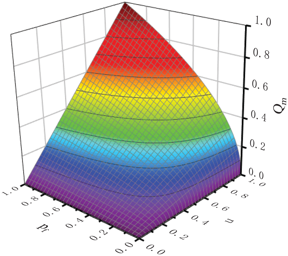
Normalized relationship of flow-pressure-input signal of PTV
Case study
To verify the effectiveness of the proposed method, different case studies are conducted by using the simulation model shown in Figure 10. It is worth noting that two hydraulic actuators are used to replace the four-chamber hydraulic actuator in the model to realize the corresponding functions.

Simulation model.
In case 1, the load forces are set as 3300, 1620, 4253, 2390 N (as shown in the first figure of Figure 11). It is used to validate the performance of NA and DA mode. In case 2, the load forces are set as 2000, 1620, 4253, 2390 N to test the effect of NA and SP mode (as shown in the first figure of Figure 12). It can be found that the load forces in case 1 and case 2 varies significantly. Moreover, the maximum load force is 4253 N and the maximum load deviation is 2633 N in both case 1 and case 2. In case 3, four sinusoidal force signals with different amplitudes are set as load forces to demonstrate the effectiveness of the proposed method under time-varying load conditions (as shown in the first figure of Figure 13). In Figures 11 and 12, the time of retraction and extension are both 10 s, and the load balancing effect in different stages is shown separately. In other figures, the time of retraction and extension are both 5 s, and the load balancing effect is shown in the same figure. To eliminate interference factors, ordinary directional valves are used as synchronization driving elements, and they are all fully open. Moreover, the main parameters of the hydraulic system are shown in Table 1.

Load balance performance in case 1.

Load balance performance in case 2.

Load balance performance in case 3.
Main parameters of the hydraulic system.

Load balancing performance under steady-state load conditions
The load balance performance in case 1 is shown in Figure 11. According to the actual situation of load forces, the best topology when the hydraulic actuator extends is that the driving units 2, 3, and 1, 4 realize DA mode respectively, that is, the case shown in the sixth line of equation 13. The obtained balanced load forces in extension stage are shown in the second figure of Figure 11 (FSO represents the balanced load force in the extension stage of the hydraulic actuator). It can be seen from the figure that the load forces of driving units 2 and 3 tend to 3500 N at the same time, and the load forces of driving units 1 and 4 tend to 3100 N simultaneously. Using the proposed load balancing method, the maximum load force can be reduced by 753 N, and the maximum load deviation between different driving units is 400 N. Therefore, the maximum load force is reduced by 18% and the maximum load deviation is reduced by 85% compared with the original load force configuration. The best driving mode in retraction stage is the NA mode in the order of 3, 4, 1, and 2, that is, the case shown in the third line of equation 5. The resulting balanced load forces are shown in the third figure of Figure 11 (FXO represents the balanced load force in the retraction stage of the hydraulic actuator). It can be seen from the figure that the load forces of all the driving units tend to 2300 N. In this case, the maximum load force decreases by 1953 N, and the load deviation is very small and can be ignored. Therefore, the maximum load force is reduced by 46% and the maximum load deviation is reduced nearly 100% compared with the original load force configuration. The speed of auxiliary pressure establishment is related to the flow through the PTV. Therefore, by reasonably designing the four chambers areas of the hydraulic actuator and the parameters of the controller, the rapid establishment of the auxiliary pressure can be realized under different working conditions.
Similarly, the load balancing performance of case 2 is shown in Figure 12. When the hydraulic actuator extends, the best topology is the DA mode between drive units 2 and 3 and SP mode between 1 and 4, that is, the case shown in the second line of equation 13. By using this combination, the load forces of at least three driving units can become consistent. It can be seen from the figure that the load forces of driving units 2, 3, and 4 tend to be the same, and the maximum load force decreases by 753 N. According to the second figure of Figure 12, the maximum load force is reduced by 18% and the maximum load deviation is reduced by 85% compared with the original load force configuration. The best topology in retraction stage is still the NA mode in the order of 3, 4, 1, and 2. In this case, the maximum load force is reduced by 2253 N and the load deviation can be ignored. Therefore, the maximum load force is reduced by 53% and the maximum load deviation is reduced nearly 100% compared with the original load force configuration.
Load balancing performance under transient load conditions and synchronization characteristic analysis
The load balancing performance of case 3 is shown in Figure 13. It can be seen from the second figure of Figure 13 that the proposed load balancing method can achieve satisfactory results even under time-varying load conditions. However, in this case, the form of auxiliary drive will also change greatly. As shown in the third figure of Figure 13, different driving forms appear in different stages and last for a period of time, according to the load force condition. It is worth noting that when the load force changes drastically, it is necessary to comprehensively consider the response characteristics of the SV, so as to avoid frequent switching. The control performance of auxiliary pressure in case 3 is shown in Figure 14. It can be seen from the figure that the proposed pressure control strategy can achieve good pressure tracking dynamic and small tracking error.
Control performance of auxiliary pressure in case 3.
The synchronization performance of three cases without balance is demonstrated in Figure 15. It can be seen from the figure that when the synchronization driving elements (directional valves) are fully open, the synchronization error is large (The maximum synchronization errors under the three operating conditions are 0.196, 0.182, and 0.292, respectively). Furthermore, the greater the load force, the worse the dynamic characteristics of the driving unit, which is the same as the conclusion obtained in Figure 6. Therefore, complex control algorithms such as cross coupling or new synchronization elements should be adopted in such system to improve the synchronization performance. In contrast, when the proposed load balancing method is applied, the design complexity of nonlinear synchronization controller will be significantly reduced. In some cases, even open-loop control can achieve satisfactory synchronization performance under large load deviations. As shown in Figure 16, even if the synchronization driving element (directional valve) is still fully open at this time, the synchronization performance under load balancing is significantly better than that in Figure 15 (The maximum synchronization errors under three operating conditions are 0.0363, 0.0229, and 0.0327, respectively). Therefore, after adopting the proposed load balancing method, the synchronization error reduction rates under the three operating conditions are 81%, 87%, and 88%, respectively.

Synchronization performance without balance.

Synchronization performance after balance.
Energy saving performance
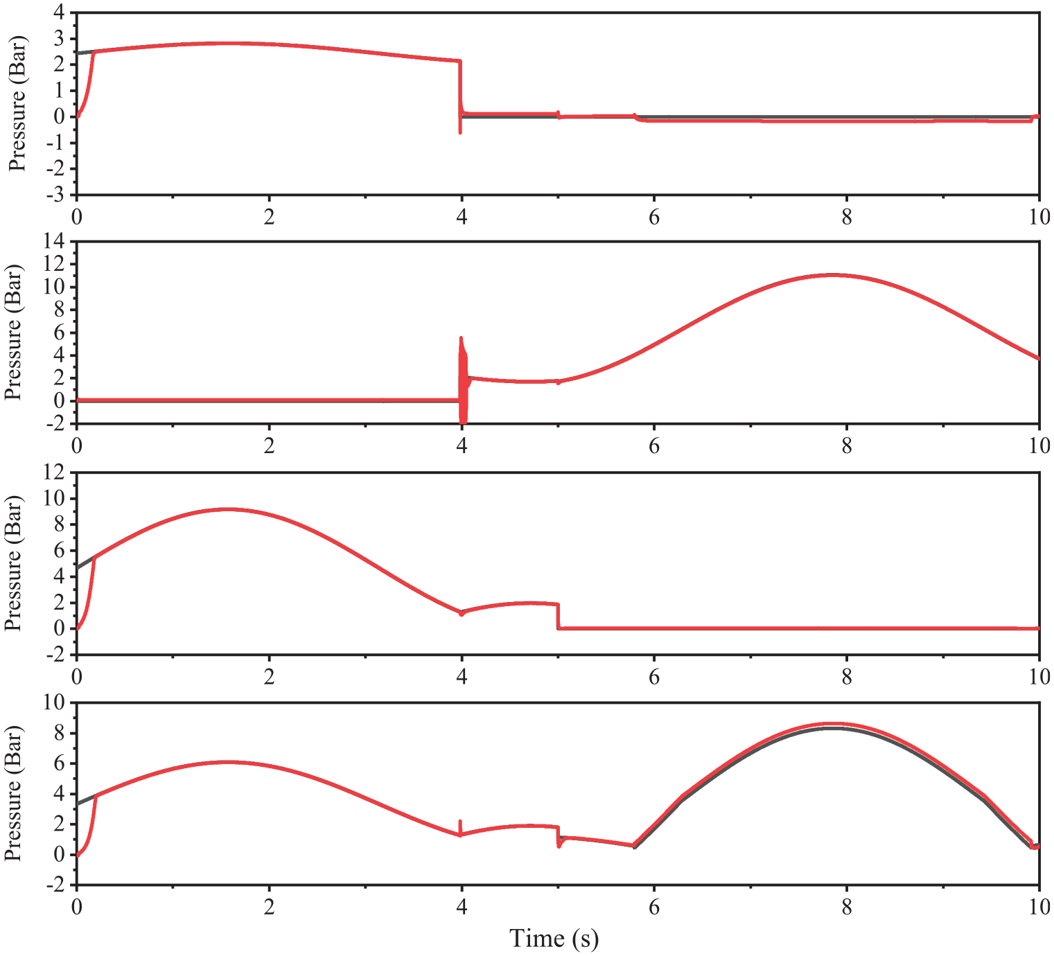
To analyze the energy-saving characteristics of the proposed method, the load sensing system based on variable displacement pump and fixed displacement pump is regarded as the pump source of the system respectively (the pressure margin is 1 bar). Although the load sensing system can reduce the pressure loss between the supply pressure and the load pressure, there is still a large energy loss when the load pressures are quite different. When using a load sensing variable pump, energy loss mainly comes from load deviation. This is because the pressure of the pump can only match the maximum load pressure, so when the maximum load pressure is high, the driving system needs to provide more energy. As the load balancing method proposed in this paper can effectively reduce the maximum load pressure, it has significant energy-saving effects. When a load sensing system based on a fixed displacement pump is adopted (i.e., the pump pressure matches the maximum load pressure through a proportional relief valve), energy loss not only comes from pressure deviation, but also from relief loss. Therefore, the energy output of the fixed displacement pump system is generally higher than that of the variable pump system, and increases with the increase of the pump flow. However, the proposed load balancing method can still effectively reduce energy loss. The pressure curves in three cases are shown in Fig. 17, where PS and PSO are the oil supply pressure before and after load balancing respectively, while Pmax and Pmaxo are the maximum load pressure before and after load balancing respectively. Based on the aforementioned analysis in section “Load balancing performance under steady-state load conditions” and “Load balancing performance under transient load conditions and synchronization characteristic analysis,” the energy output and consumption reduction can be calculated, which is shown in Figures 18 and 19. From the figure, it can be seen that for the load sensing system based on variable displacement pump, the highest energy-saving rate reaches 43% and the average energy-saving rate is 24%. For load sensing systems based on fixed displacement pump, the highest energy-saving rate reaches 14% and the average energy-saving rate is 12%. It can be inferred that the proposed load balancing method has significant energy-saving effect in different working conditions and different movement stages. Therefore, the proposed method can further improve the system efficiency on the basis of load sensing system.

Pressure curves after balance.

Energy consumption characteristics of the system (load sensing-variable displacement pump).
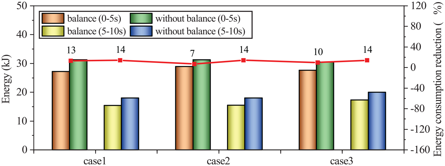
Energy consumption characteristics of the system (load sensing-fixed displacement pump).
Conclusions
In this paper, a bionic driving method of multi-actuator hydraulic synchronization system is proposed based on the cluster flight principle of wild goose. The switching rules of system topology and auxiliary pressure control strategy are discussed, and the beneficial effects of this method are analyzed from the perspective of synchronization performance and energy saving. The main conclusions are summarized as follows.
According to the analysis in section “Load balancing performance under steady-state load conditions,” the maximum load force and the maximum load deviation can be reduced by 18% and 85% respectively when actuators extend. Moreover, the maximum load force decreases by an average of 50% and the maximum load deviation is reduced nearly 100% when actuators retract.
According to the analysis in section “Load balancing performance under transient load conditions and synchronization characteristic analysis,” the proposed method can make the main characteristics of each driving unit tend to be consistent, so as to reduce the synchronization error by 81%, 87%, and 88% respectively under the three operating conditions. Therefore, the proposed method can reduce synchronization error by more than 80% under typical operating conditions.
According to the analysis in “Energy Saving Performance” it can be concluded that the proposed load balancing method can further reduce the energy consumption (average 24% and 12% for load sensing system based on variable displacement pump and fixed displacement pump, respectively) on the basis of load sensing system.
In addition, this method can adapt to both constant load and time-varying load, and can be further extended to other equipment or occasions with multiple hydraulic actuators.
Footnotes
Handling Editor: Sharmili Pandian
Declaration of conflicting interests
The author(s) declared no potential conflicts of interest with respect to the research, authorship, and/or publication of this article.
Funding
The author(s) disclosed receipt of the following financial support for the research, authorship, and/or publication of this article: This work is supported by the basic science research projects of higher education institutions in Jiangsu Province (natural science) [Grant No. 23KJB460013]; Basic research plan of Xuzhou city [Grant No. KC23005]; Innovation and entrepreneurship training program for college students in Jiangsu Province [Grant No. 202310320142Y].