
Abstract
In this study, a novel curved Euler beam quasi-zero stiffness (CE-QZS) isolator is proposed by limiting the displacement of the curved Euler beam to change its deformation mode, and the excellent vibration isolation properties are presented. The static and dynamic properties and parameter influences are investigated to identify the isolation mechanism of the novel isolator through numerical simulation using the finite element analysis. These studies of the proposed structure show that compared to the curved Euler beam structure, the bearing capacity and quasi-zero stiffness (QZS) range of the CE-QZS isolator have been significantly improved, and the original negative stiffness of the curved Euler beam is eliminated. Moreover, by changing the position of the rails, the position of the QZS range can be altered, allowing for full utilization of the structural space. Furthermore, the bearing capacity, working range, and QZS range of the CE-QZS isolator can be designed by adjusting the spring stiffness and geometric dimensions of the curved Euler beam. The experimental prototype is machined to conduct vibration tests that confirm the accuracy of the simulation analysis and the superiority of the proposed structure.
Keywords
Introduction
Passive vibration control has attracted considerable attention owing to its simple structure, low cost, and high reliability. 1 Traditional linear passive isolators can achieve low-frequency isolation by reducing stiffness. However, this leads to a contradiction between the high bearing capacity and low-frequency vibration isolation or results in system instability.2–4
Quasi-zero stiffness (QZS) isolators have been widely studied and applied because of their unique design,5–10 which enables them to simultaneously possess a high bearing capacity and achieve low-frequency vibration isolation. The combination of positive and negative stiffnesses can cause the structure to obtain a quasi-zero stiffness. Based on this principle, researchers have proposed various QZS isolators. For example, Carrella et al. proposed a QZS isolator with two pre-compressed inclined springs and one vertical spring.11,12
QZS isolators with appropriate parameters are better than linear isolators, and the force and displacement transmissibility of these QZS isolators are different. Ding et al. proposed a spiral spring structure 13 to reduce the vibration hazards in fluid pipelines. Zhou et al. studied the cam-roller structure14–16 and achieved QZS by modifying the shape curve of the cam-roller, which greatly enhanced the designability of the cam-roller structure. Jing et al. proposed an X-shaped structure composed of linear springs and link rods,17–20 which generates QZS through a special geometric relationship. Wu et al. utilized the nonlinearity force of magnetic repulsion to design a magnetic spring QZS isolator,21–23 and its superiority was verified through vibration experiments. Niu et al. 24 designed a QZS isolator using disks and linear springs. They found that the excitation amplitude and offset distance to the zero dynamic stiffness position could affect the response and resonance frequency.
In our previous study, a bio-inspired QZS isolator was proposed and further developed a six-degree-of-freedom isolator. Furthermore, a novel combined vibration isolator with a wider working range was also designed and studied.25–27 The above QZS isolators exhibit high static stiffness and low dynamic stiffness (HSLD) and low-resonance frequency. The research achieved excellent vibration isolation performance in the low-frequency range while maintaining a high bearing capacity.
In addition, the slender Euler beam has a simple nonlinear structure, which exhibits nonlinear characteristics within the deformation range near the buckling range; it has received significant research attention owing to its nonlinearity. Santo et al. studied the harmonic response of vibrating rods with an array of nonlinear springs, 28 the interaction of vibration modes and the influence of periodic local nonlinearity on the dynamic behavior of bars are studied by theoretical methods. Akano and Olayiwola studied the nonlinearity of the flexible beam subjected to large deformation by using the multi-step differential transformation method, 29 and the approximate solution is obtained on the basis of establishing the boundary conditions.
Huang et al. studied a nonlinear QZS isolator that uses a buckled Euler beam as a negative-stiffness corrector, 30 and their superior vibration isolation performance has been confirmed. Fan et al. designed elements using sine beams, semi-circular arches, and harder walls. 31 Therefore, QZS isolators can be designed for different applications by combining the QZS structures with different elements. Oyelade designed a structure for car seats using curved Euler beams instead of linear springs to improve comfort. 32 Hua designed a nonlinear isolator with good impact resistance using two pairs of Euler beams as the negative-stiffness component. Liu et al.33,34 used a curved Euler beam, simply supported as a QZS isolator, for a negative-stiffness corrector and investigated the effect of Coulomb friction on the isolation efficiency. They found that increasing the Coulomb friction could effectively reduce the vibration transmissibility.
Lu and Han et al.35–37 utilized circular and elliptical ring beams under compression to design a nonlinear QZS isolator for circular and elliptical rings based on their force–displacement expressions at different compression stages. They also used shape memory pseudoelasticity ropes to enhance the isolation performance of circular ring isolators and compared the effects of different alloy ropes on the isolation performance. Chao et al. proposed a QZS isolator using Euler beams as a positive-stiffness component, 38 and the results showed that the isolator could achieve low-frequency isolation and high bearing capacity while maintaining minimal vibration displacement. Banerjee et al. utilized the nonlinear properties of Euler beams for energy harvesting, 39 while the QZS structure is employed to convert detrimental vibrations into usable energy, which represents a commendable approach.
Curved Euler beams have simple structure, strong practicality, and stable mechanical and bistable characteristics, which have been widely studied by researchers. Euler beams are often used in low-frequency vibration energy collectors and consumers owing to their bistable characteristics. However, these characteristics render it unable to bear a large load when used as a negative-stiffness component in a QZS structure. Isolators with Euler beams lose a substantial working range and can potentially cause displacement mutation and structure instability. In addition, the aforementioned studies mainly focused on Euler beams subjected to axial force pre-compression. However, there has been little research and improvement based on their bistable characteristics, and there has been less research on curved Euler beams subjected to lateral forces.
In this study, a curved Euler beam quasi-zero stiffness (CE-QZS) isolator is proposed based on the above facts. It uses a curved Euler beam as a negative-stiffness component to change its deformation mode and static characteristics through one vertical spring and two rails. It utilizes the negative-stiffness characteristic of a curved Euler beam in a two-state transition stage. By introducing a positive-stiffness spring (positive stiffness) and rails (limiting the lateral displacement and rotation at two points on the beam) to change its force–displacement relationship, the structure exhibits QZS or positive stiffness during two steady-state transition processes. Thus, the instability factors of the Euler beam are eliminated, and the stability and isolation performance of the isolator are improved. The position of the QZS range can be flexibly adjusted by changing the position of the rails.
The static and dynamic characteristics of the new structure are studied using the numerical simulation using the finite element analysis. Compared with a single Euler beam structure, the isolator has better high-static and low-dynamic characteristics. The results show that this structure has a better bearing capacity, larger QZS range, and better low-frequency vibration isolation performance. Based on the above results, parameter studies are conducted to determine how to improve the vibration isolation performance. Finally, a prototype of the CE-QZS isolation platform is designed for vibration testing to verify the accuracy of the simulation results. The isolation platform consists of two CE-QZS isolators in parallel, and no additional structures are used to maintain the stability of the prototype. These results show that the new isolator has excellent vibration isolation performance at low frequencies and good bearing capacity and space utilization. This study contributes to improving the use of curved Euler beams in vibration isolators.
Proposed CE-QZS isolator
The proposed CE-QZS isolation platform comprises a curved Euler beam, a vertical linear spring, and two rails. As shown in Figure 1, a three-dimensional structure diagram of a CE-QZS isolator and a diagram of a single CE-QZS structure are established using SolidWorks software. The isolator consists of two CE-QZS structures, where the dark blue surfaces in the figures represents the galvanized surfaces of this structure, which are used to minimize friction during movement. To simplify the analysis, the numerical simulation using Multiphysics FEA does not take into account the friction caused by relative motion between structures.

(a) Three-dimensional structure of the CE-QZS isolation platform and (b) structural diagram of single CE-QZS isolator.
In Figure 1, L represents the span of the curved Euler beam, h represents the height of the curved Euler beam, b represents the width of the curved Euler beam, d represents the thickness of the curved Euler beam, and s represents the distance between the rail and midpoint of the beam. A vertical linear spring with stiffness k was set inside the sleeve to support the bearing platform with the Euler beams.
Methodology
Displacement expression
When a 2D beam is subjected to axial and bending loads, its axial displacement u is a linear function of x, and the deflection v is a cubic function of x. Assuming the expressions for its axial displacements u and transverse deflection v are:


where ai and bi are the undetermined constants of the displacement mode, and the number of the undetermined constants is the same as the number of degrees of freedom of the element node.
In this study, each node of the beam element has displacement in the direction of x, y and angle θ, then the displacement vector of the element node can be expressed as:

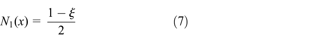
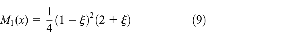
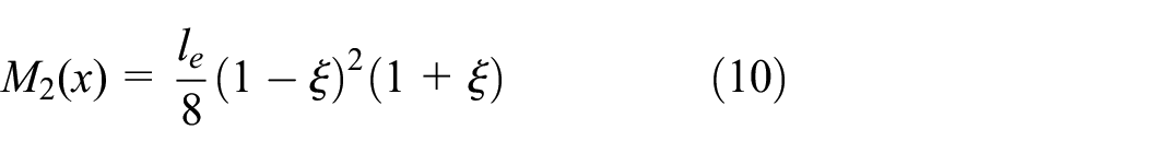
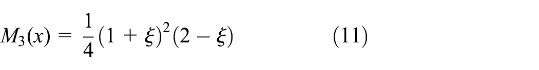
where ui and vi are the displacement of node i along the local coordinates, θi is the angle of the interface at node i. 37 The displacement can be expressed in the following forms based on the finite element analysis:


Equations (4) and (5) can be expressed in a matrix form:

where the elements in equation (6) can be expressed as follows:


where
Total Lagrangian (T.L) incremental method
In this paper, the Hamiltonian energy principle based on total Lagrangian (T.L) description, a dynamic model of geometrically nonlinear beams is established with the nonlinearity of beam is considered. The Lagrange geometric nonlinearity is taken as the reference configuration, and the nonlinear finite element equation can be got by the T.L method.
The geometrically nonlinear finite element equation of a beam, each incremental step of the solving process is regarded as each incremental time t of the deformation process, where the initial configuration is used as the reference configuration. ux, Exy, and Sxy represent the displacement, the Green strain and the Kichhoff stress respectively. When the incremental time is Δt, the incremental displacement, incremental strain and incremental stress Δux, ΔExy, and ΔSxy of object under the incremental load.
The Green strain can be expressed as

where xl, xm, and xn represent the three directions of coordinates, ul, um, and un represent the displacements in three directions.
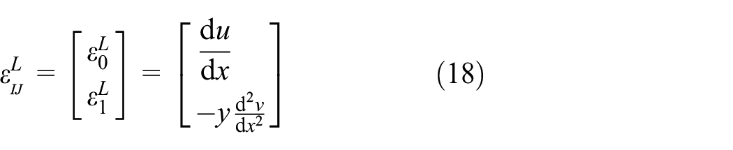
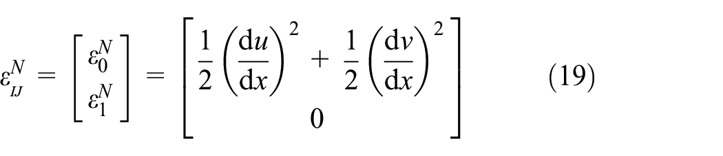
The incremental strain of the beam element

where the expressions of linear strain
The element strain increment during the i-th incremental step from the time t to t + Δt is:

where

Substituting equation (6) into equation (18), the linear geometric matrix [BL] can be obtained

The nonlinear geometric matrix

where:


Supposing

When the initial strain of the beam is 0, then

where the element elasticity matrix [D] has the following expression:

The strain energy of the element can be obtained by

The gravitational potential energy of the element is:

where ρ is the mass density.
The external forces acting on the element can be equivalent to a concentrated force acting on the element. Therefore, the potential energy of the external force of the element is

where {F} is the concentrated force vector.
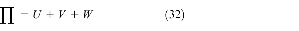
The instantaneous total potential energy of the element is expressed as:
According to the variational principle, the following equation can be obtained when

According equations (6), (26), (29), and (30)–(33), the dynamic equation of beam in T.L format can be obtained as the following form:

Where
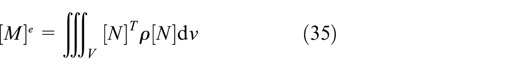

where [kL]e is the linear stiffness matrix, [kN]e is the nonlinear matrix and [k0]e is the stiffness matrix of the spring constraint, they have the following forms:


where
Coordinate system transformation
In this paper, the local coordinate directions of the curved Euler beam are different. Therefore, the characteristic matrix of the elements needs to be transformed into the global coordinate system by a transformation matrix. As shown in Figure 2, the beam element in the global and local coordinate systems, where the global coordinate system is represented by

Local and global coordinate systems.
As shown in Figure 2, the relationship between the local coordinate system and the global coordinate system as:

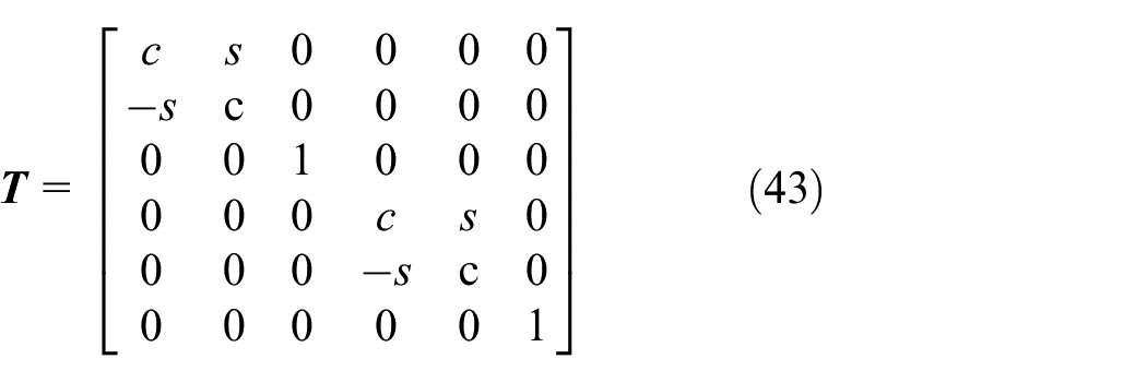
where c = cosβ, s = sinβ and β is the angle between the local coordinate system and the global coordinate system axis. Therefore, the relationship between the displacement of the element node in the local coordinate system and the displacement of the element node in the global coordinate system as:

The matrix form of equation (41) is:

in which:
Substituting the equation (43) into the finite element equation and multiplying the equation by


According to the above theory of finite element method of nonlinear beam elements, the structure can be solved and analyzed after combing the element matrix and vector. Assembling the element matrix in the global coordinate system and considering the boundary conditions, the global equation of motion can be obtained:

where
In this paper, the structure is a CE-QZS isolator, and the static and dynamic properties of the structure are studied by FEM, including stiffness characteristics and vibration isolation transmissibility. The CE-QZS isolator utilizes the geometric nonlinearity of the curved Euler beam, the relationship between the force and displacement of the element nodes is established by discretizing the structure into a finite number of small elements, and the stress and strain of each element are obtained according to the known boundary conditions. On this basis, the vibration isolation transmissibility curve of CE-QZS can be calculated. The stiffness and vibration isolation transmissibility characteristics can be studied more accurately by utilizing finite element simulation software, which provides important support for the design and development of QZS isolator.
Nonlinear static simulation analysis
Study of static characteristics on CE-QZS isolator
In this section, the nonlinear static characteristics of the CE-QZS isolator are investigated using the COMSOL Multiphysics software. The advantages and feasibility of the new structure are illustrated by comparing the structures before and after the improvement. The parameters are studied to explore the influence of different parameters on structural statics.
Figure 3 shows the schematic of the curved Euler beam isolator (comparative structure I), and Figure 4 shows the schematic of the structure after introducing a vertical spring to the midpoint of the curved Euler beam (comparative structure II). Both ends of the beam are fixed constraints and the midpoint of the beam is subjected to a vertical force that reflects the actual mechanical characteristics. Figure 5 shows a schematic of the CE-QZS isolator. The simulation model primarily comprised an elastic manganese Euler beam, a vertical linear spring, and two rails (set at points A and B). The ends of the beam are fixed constraints, the midpoint of the beam and spring is subjected to a vertical force, and the displacements of points A and B are limited, except in the vertical direction. These settings can accurately reflect the mechanical characteristics of the CE-QZS isolator.

Geometric schematic of the comparative structure I.

Geometric schematic of the comparative structure II.

Geometric schematic of the CE-QZS isolator; blue represents the curved beam before deformation and black represents the curved beam after deformation.
Figure 6 shows the comparative structure I established in the numerical simulation using the COMSOL Multiphysics software, which uses solid elements. The material is 65 Mn steel, and its material parameters are as follows: elastic modulus E = 196 GPa, Poisson’s ratio μ = 0.25, and density ρ = 7.81 × 10³ kg/m3. The geometrical parameters of the curved Euler beam without special instructions are as follows: L = 400, h = 100, b = 3, and d = 0.3 mm. The working range of this isolator is 0–100 mm. The ends of the beam were fixed, and a vertical force was applied at its midpoint.

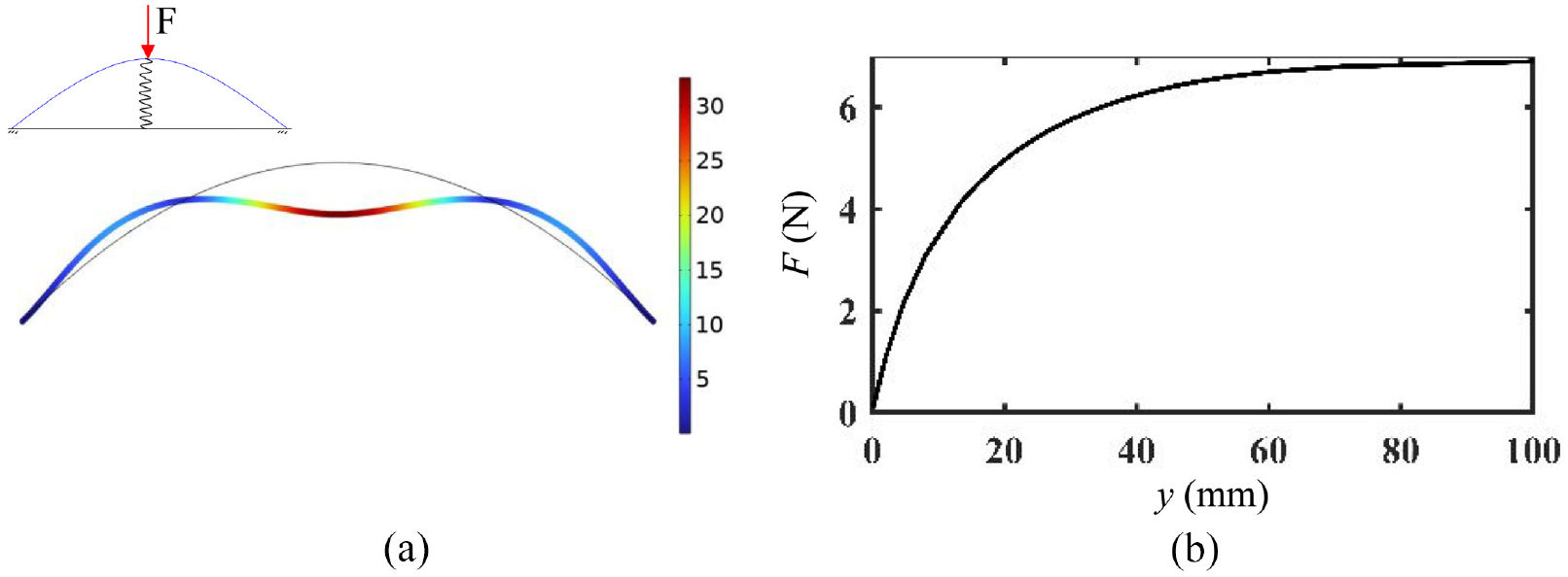
(a) Stress nephogram under max bearing position and (b) stress nephogram undermax compression position.
Figure 6(a) and (b) show the maximum bearing and maximum compression positions of comparative structure I during compression, respectively. The maximum stress and strain occurred in the middle of the curved Euler beam. Figure 6(a) shows that the maximum force F is 4.1 N, which the beam can withstand, and the vertical displacement y of the midpoint is 33.55 mm. The isolator has a negative stiffness during the compression from 33.5 to 100 mm.
As shown in Figure 7, the force–displacement and stiffness–displacement curves in the compression process are obtained through a static simulation. Figure 7(b) shows that the positive-stiffness range is 0–33.55 mm and the negative-stiffness range is 33.55–100 mm throughout the entire working range. The structure has a negative stiffness in most working ranges, which results in poor space utilization and instability of the curved Euler beam, making it difficult to operate in isolators. Moreover, the bearing capacity of the isolator is limited, making it unsuitable for practical engineering applications. The curved Euler beam was then directly used as an isolation device, which might result in structural instability during compression. Therefore, further design improvements were required to achieve proper utilization of the structure.

(a) Force–displacement and (b) stiffness–displacement curves of comparative structure I.
Figure 8 shows the deformation mode and force–displacement curves of comparative structure II. As seen in Figure 8(b), the force–displacement curve is continuous, indicating that the spring enables the isolator to achieve positive stiffness throughout the working range, and the bearing capacity of the structure is slightly improved. In addition, there was only a minimal QZS at the end of the working range.
(a) Stress nephogram and (b) force–displacement curve of comparative structure II.
Figure 9 shows the deformation mode and force–displacement curves of the CE-QZS isolator. The mechanical characteristics of this structure changes significantly after the improvements. It can be observed that the bearing capacity has been greatly improved, the new working range is (0, 70 mm), the QZS range has been expanded, and the QZS range lies in the middle of the total working range. These changes are beneficial for improving the bearing capacity, stability, and isolation performance of the isolators and provide scientific support for the application of QZS isolators with curved Euler beams.

(a) Stress nephogram and (b) force–displacement curve of CE-QZS isolator.
Figure 10 shows the comparative force–displacement and stiffness–displacement curves of comparative structure I and the CE-QZS isolator. Figure 10(a) indicates that the bearing capacity and QZS range of the structure increases significantly compared with those of the Euler beam, and the working range is reduced. The bearing capacity of the CE-QZS isolator is 60 N and that of the curved Euler beam is 4 N. In Figure 10(b), the positive-stiffness range of the Euler beam is 0–33.5 mm, and the negative stiffness range is 33.55–100 mm. However, the CE-QZS isolator has a QZS range of 10–30 mm, and no negative stiffness was observed in the 0–70 mm range. The bearing capacity of the CE-QZS isolator is approximately 15 times that of the curved Euler beam, with a large QZS range. These improvements indicate that the new isolator exhibits good static characteristics.

Comparison of (a) force–displacement and (b) stiffness–displacement curves between the CE-QZS isolator and comparative structure I.
Parameter influence on static characteristics
The above analysis indicates that the CE-QZS isolator has an advanced bearing capacity and QZS characteristics. The parameters include the span L, height h, and thickness d of the curved Euler beam and the distance between the rail and midpoint of the beam s. The numerical simulation using the COMSOL Multiphysics software was used to study the structural parameters and explore their influence on the structural static characteristics. The structural parameters are set as: span L = 400 mm, height h = 100 mm, width b = 3 mm, thickness d = 0.3 mm and s = 100 mm, without special instructions. Because the spring stiffness k must change with the curved Euler beam, when studying the influence of other parameters, only the isolator is required to possess QZS characteristics, and there is no specific requirement for the spring stiffness k. Therefore, an appropriate spring stiffness k should be set to ensure that the isolator has QZS characteristics when studying the influence of the other parameters.
First, the influence of the span L of the beam on the static characteristics was studied. The values of L were 400, 450, and 500 mm. A comparison of the force–displacement and the stiffness–displacement curves is shown in Figure 11. As shown in the figure, the bearing capacity and QZS range of the structure decrease as L increases. In addition, the working range of the isolator decreases when L decreases. When L = 400 mm, the working range of the isolator is 70 mm. The stiffness decreases again when the displacement is approximately 35 mm, which is caused by a change in the deformation mode of the Euler beam during compression. Therefore, the span L should be reduced to ensure that the isolator exhibits good static characteristics.

Comparison of (a) force–displacement curves and (b) stiffness–displacement curves for different values of span L of Euler beam.
While the other structural parameters remain unchanged, the height h of the curved Euler beams is selected as 100, 110, and 125 mm. A comparison of the force–displacement and stiffness–displacement curves is shown in Figure 12. The results show that the bearing capacity increases, the working range increases, and the QZS range increases slightly as the h increases. The maximum stiffness of the structures is approximately the same. Therefore, a smaller height h can provide better bearing capacity for the isolator, whereas a larger height h can provide a larger QZS range.

Comparison of (a) force–displacement curves and (b) stiffness–displacement curves for different values of height h of Euler beam.
While the other structural parameters are kept unchanged, the thickness d of the curved Euler beams is selected as 0.2, 0.25, 0.3, 0.35, and 0.4 mm. Figure 13 shows a comparison of the force–displacement and stiffness–displacement curves. According to Figure 13, as the value of d increases, the bearing capacity of the structure increases; however, the QZS and working ranges barely change. The change in thickness significantly affects the bearing capacity. Based on this feature, we can conclude that the thickness d can be flexibly adjusted such that the isolator has a better static performance.

Comparison of (a) force–displacement curves and (b) stiffness–displacement curves under different values of thickness d of Euler beam.
While the other structural parameters remain unchanged, the distance s between the rail and midpoint of the beam is selected as 75, 100, and 125 mm. Figure 14 shows a comparison of the force–displacement and stiffness–displacement curves. According to Figure 14, the working range of the isolator increases with an increase in s, and the bearing capacity and QZS range of the isolator decrease. Moreover, the QZS range sharply decreases for s = 75 mm, which is not conducive to low-frequency vibration isolation.
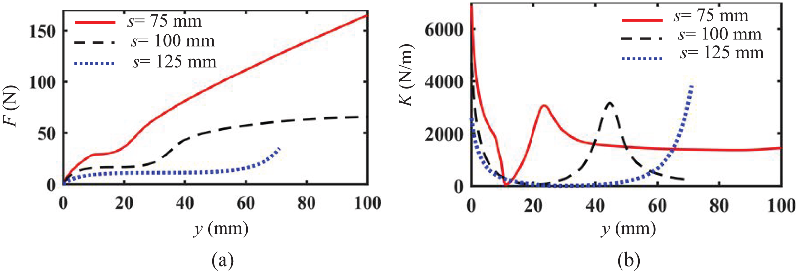
Comparison of (a) force–displacement curves and (b) stiffness–displacement curves for different values of distance s between the rail and midpoint of the beam.
It is important to emphasize that under conditions of the rail limitation, the isolator fails to demonstrate QZS characteristics. For example, when s = 200 mm, the force displacement curve of the structure is shown in Figure 8, and the performance of the isolator decreases. Therefore, on the premise of ensuring that the structure has QZS characteristics and the rails are effective, an increase in s leads to better QZS characteristics of the isolator.
In conclusion, changes in various parameters have different effects on the static characteristics. The working range of the isolator increases as L and h increase and decreases as s decreases. The QZS range of the structure increases as L decreases and h and s increase. Therefore, smaller values of L and larger values of h and s should be selected for an optimal bearing capacity. Parameter d, owing to its minimal influence on the working range and QZS characteristics and significant influence on the bearing capacity of the structure, can be flexibly selected to ensure optimal bearing capacity and QZS range.
Dynamics simulation analysis
Study of vibration isolation performance on CE-QZS isolator
Based on the analysis presented in Section 3, it is concluded that the CE-QZS isolator must possess good static characteristics to meet the actual working requirements for bearing capacity and QZS characteristics. As mentioned before, the numerical simulation using the COMSOL Multiphysics software is used to analyze the frequency response of the isolator. The base is excited by a sinusoidal force, the response of the isolated object is obtained, and the force transmissibility is calculated to evaluate its vibration isolation performance. After completing the above analysis, the parameters can be selected based on the bearing capacity requirements and the isolation performance in dynamic analysis, and the optimal design parameters of this isolator can be determined based on the above two conditions.
In this study, the parameters mentioned in Section 3 are used as the basic structural parameters. The spring stiffness k = 450 N/mm, the mass of the isolated object m = 1 kg, the damping coefficient is 0.25, and the excitation amplitude is z0 = 1 N. Figure 15 shows the force transmissibility (Tf) curve of the structure. The coordinates of the curve peak are (2.85 Hz, 2.866), indicating that the resonance frequency of the CE-QZS isolator is 2.85 Hz and the response amplitude is 2.866. The starting vibration isolation frequency is approximately 4 Hz, indicating that the structure exhibits vibration isolation when the frequency of the external excitation is greater than 4 Hz. Based on the static analysis in Subsection 3.1, we conclude that when the mass of the isolated object m = 1 kg, the equivalent stiffness of the structure is approximately 343 N/m. According to the classical theory of vibration mechanics

Force transmissibility curve of CE-QZS isolator.
Parameter influence on vibration isolation performance
Based on the above static simulation results, dynamic simulation results, and comparison of the resonance frequency, it is inferred that the improved QZS isolator has a satisfactory low-frequency vibration isolation performance. Similarly, a detailed analysis of the influence of different parameters, including the span L, height h, thickness d of the beam, distance s between the rail and midpoint of the beam, and mass m of the isolated object, on the vibration isolation performance was conducted. By exploring the vibration isolation mechanism of the isolator using parameter analysis, particularly the influence of the geometric parameter changes of the curved Euler beam, guidelines can be provided for structural design and application.
First, the influence of the span L on the vibration isolation performance was studied with the other structural parameters unchanged. The values of L are selected as 400, 450, and 500 mm, and Figure 16 shows a comparison of the force transmissibility curves. As shown in the figure, the value of the force transmissibility curve peak increases as L increases, and the starting vibration isolation frequency increases slightly. When L increases from 400 to 500 mm, the resonant frequency increases from 3.1 to 4 Hz, and the transmittance replication increases from 3.8 to 4.6, the vibration isolation performance is reduced. When the parameter change has a minimal impact on the structural stiffness, the impact on the vibration isolation performance is also minimal. Therefore, the change in span L has minimal effect on the vibration isolation performance.

Force transmissibility curves of the CE-QZS isolator for different values of span L of the beam.
The values of h are selected as 100, 110, and 120 mm with other structural parameters unchanged, and Figure 17 shows the comparison of the force transmissibility curves. As shown in the figure, the vibration isolation performance of the structure decreases as the value of h increases, and both the resonance frequency and force transmissibility increase. As shown in Figure 12, the bearing capacity decreases as h increased. When h = 125 mm and m = 1 kg, the CE-QZS isolator’s equilibrium position shifts to the high-stiffness range rather than the QZS range, leading to a substantial increase in both its resonance frequency and force transmissibility. Thus, a smaller height h should be selected based on the actual requirements while satisfying the bearing capacity requirements to ensure good low-frequency vibration isolation performance.
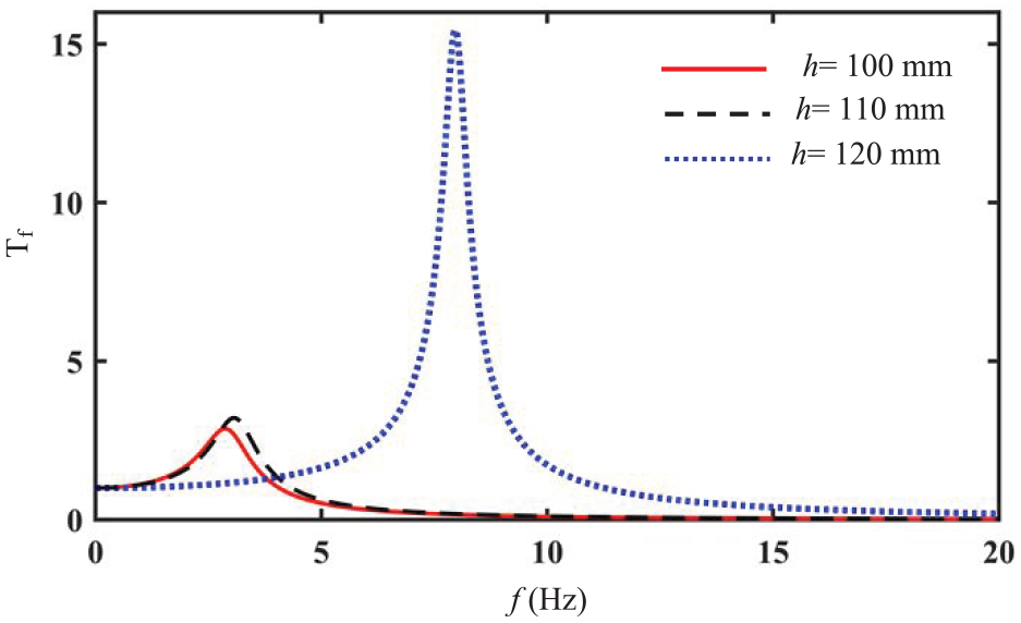
Force transmissibility curves of the CE-QZS isolator for different values of height h of the beam.
The values of d are selected as 0.2, 0.25, 0.3, 0.35, and 0.4 mm with other structural parameters unchanged, and Figure 18 shows a comparison of the force transmissibility curves. As shown in this figure, the vibration isolation performance of the structure deteriorates when the h increases from 0.3 to 0.4 mm. As shown in Figure 13, the bearing capacity decreased as d decreased. When d = 0.2 mm or 0.25 mm and m = 1 kg, the equilibrium position of the new isolator is located in the high-stiffness range, resulting in higher resonance frequency and force transmissibility amplitude than at d = 0.3 mm, and its vibration isolation performance deteriorates. Therefore, a smaller d should be selected to ensure a better vibration isolation performance of the isolator within an appropriate range.

Force transmissibility curves of the CE-QZS isolator for different values of thickness d of the beam.
The distance s between the rail and midpoint of the beam is selected as 75, 100, and 125 mm, with other structural parameters unchanged. Figure 19 shows the comparison of the force transmissibility curves, illustrating that the force transmissibility amplitude and resonance frequency of the isolator decrease as s increases from 75 to 125 mm, indicating improved vibration isolation performance. In summary, the vibration isolation performance of the structure deteriorates as s increases, when the mass m causes the equilibrium position of the isolator to lie in the QZS working range.

Force transmissibility curves of the CE-QZS isolator for different values of distance s between the rail and midpoint of the beam.
To ensure that the static equilibrium position of the isolator resides in the QZS range, the mass m was varied from 0.5 to 1.5 kg while keeping the other structural parameters constant. Figure 20 presents a comparison of the force transmissibility curves. In this figure, the force transmissibility amplitude and resonance frequency of the structure increase as m decreases, indicating that the vibration isolation performance declines. Therefore, the isolation performance of the QZS isolator improves as m increases, when the mass m of the isolated object is within the allowable bearing capacity.

Force transmissibility curves of the CE-QZS isolator for different values of mass m of the isolated object.
According to the parametric studies in Sections 4 and 5, the influence of each parameter on the isolator is shown in Table 1.
Effects on the vibration isolation performance when each parameter increases, where ↑ represents increasing and ↓ represents decreasing.

Experimental research
Based on the simulation calculations and parameter analysis, a prototype of the CE-QZS isolation platform was designed to conduct vibration experiments. The accuracy of the simulation and low-frequency isolation performance of the CE-QZS isolator were verified through experimental results.
The prototype consisted of two parallel CE-QZS isolators symmetrically set to support the bearing platform, ensuring platform stability. The structure was made of lightweight aluminum to reduce the impact of mass on the experiment, except for the spring and curved Euler beams. In addition, the material of the spring was 304 steel, and the spring was placed in the sleeve of the base. The curved Euler beam was made of 65 Mn elastic manganese steel with an elastic modulus E = 2 × 10¹¹ Pa. There was only a vertical relative motion between the bearing platform and base during the vibration process when installing the vertical sliding bearings. The platform and rails were connected to the midpoint of the curved Euler beam using thin cylindrical rods to reduce the influence of a large contact area.
A vibration test system was used in the experiment, which included a shaker, a power amplifier, signal generation and collection equipment, and a computer control system. The shaker had a rated sinusoidal thrust of 300 kgf (2940 N), rated speed of 2 m/s, rated frequency of 2–4000 Hz, and rated displacement of 25.4 mm. The signal collector converts the acceleration signal into an electrical signal. The acceleration transmissibility was then obtained by comparing the amplitude of the external excitation with the response of the platform, which was used to evaluate the vibration isolation performance.
The mass of the bearing platform and its accessories was 0.35 kg. Spring stiffness was measured using static experiments, and the values in Table 2 are the average values of multiple experiments. The corresponding model parameters are listed in Table 2, and the prototype and experimental devices are shown in Figures 21 and 22, respectively. The experimental process as shown in Figure 22 is as follows: (1) the computer controls the signal generator to generate the excitation signal, (2) which is amplified by the power amplifier and transmitted to the shaker, (3) and the shaker begins to push the isolator to vibrate. (4) The data collector obtains feedback signals through acceleration sensors installed on the shaker and bearing platform. (5) Finally, the experimental data are processed using a computer.
Structural parameters for prototype.


Diagram of the CE-QZS isolation platform.

Experimental setup and process.
The total mass M was 2.12 kg, and the static equilibrium displacement was approximately 12 mm in this experiment. The acceleration amplitude of the external excitation was a = 0.01g (g = 9.8 N·m/s 2 ), which could be converted into a force excitation amplitude of 0.87 N (F = m·a). The force transmissibility was obtained by comparing the response amplitude with the excitation amplitude. Figure 23 shows a comparison between the experimental and simulation results, and the red and black curves show the numerical simulation using the COMSOL Multiphysics software and experimental results, respectively. The peak coordinates of the red and black curves are (6.41 Hz, 3.906) and (6.59 Hz, 4.026), respectively. The differences in the two curves in this figure are caused by errors in the installation, friction and damping of the prototype in the experimental and simulation analysis. The two curves are in good agreement within the testing frequency range, especially near the resonance frequency, proving the correctness of the simulation results. This verifies that the CE-QZS isolator has an excellent low-frequency vibration isolation performance.
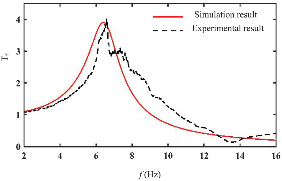
Comparison of the force transmissibility between experimental and simulation results.
Conclusions
Based on the analysis of the negative-stiffness characteristics of a curved Euler beam during compression, the deformation mode of the curved Euler beam is changed using linear springs and rails, and a CE-QZS isolator with enhanced vibration isolation performance is proposed, which exhibits good bearing capacity and QZS characteristics. Statics, dynamic, and parameter analyses of the new isolator were performed using the numerical simulation using the COMSOL Multiphysics software. A vibration experiment was conducted on the designed prototype for validation. The accuracy of the simulation analysis was verified based on the good agreement between the experimental and simulation results. The main findings are summarized as follows:
(1) According to the statics analysis of the isolator, the proposed CE-QZS isolator eliminates the original negative stiffness and bistable characteristics of the curved Euler beam and has high static and low dynamic stiffness. The bearing capacity and QZS range are significantly improved, and larger working and QZS ranges can be achieved by introducing a linear spring with appropriate stiffness.
(2) According to the dynamic structural analysis, the CE-QZS isolator can achieve vibration isolation at low frequencies owing to its QZS characteristics. The new isolator achieves a better energy dissipation performance and a lower response amplitude by adjusting the damping of the spring.
(3) Parameter analysis of the structure using the COMSOL Multiphysics software reveals that to ensure high static and low dynamic characteristics for the isolator, an optimal bearing capacity, smaller L, h, and d, and a larger s should be selected. For example, according to the results of different values of the parameters studied in the previous text, when m = 1 kg, the optimal parameters are: L = 400, h = 100, d = 0.3, and s = 125 mm. In addition, the working range of this isolator increases as L and h increases and decreases as s decreases. For its vibration isolation performance, the change in span L has minimal effect on the vibration isolation performance of the structure. A large distance s (must be within the limit value of the rails) and mass m are beneficial for optimal vibration isolation performance, and smaller height h and thickness d are preferred for improved vibration isolation performance. Therefore, parameter selection and isolator design should be based on the above findings. It should be noted that the thickness d has a slight effect on the QZS characteristics and size of the working range, which can be flexibly adjusted to improve the working performance of the CE-QZS isolator.
(4) An experimental prototype was designed for the vibration experiments to obtain the force transmissibility of the new isolator. The accuracy of the simulation analysis was verified by comparing the experimental results with the simulation results. Figure 23 shows a comparison between the experimental and simulation results, and the peak coordinates of the simulation result and experimental result are (6.41 Hz, 3.906) and (6.59 Hz, 4.026), respectively. Moreover, the experimental results indicate that the CE-QZS isolator exhibits good low-frequency vibration isolation performance.
In this study, a systematic analysis of the CE-QZS isolator was conducted, and its superiority was verified. The improved isolator based on the curved Euler beam clearly offers numerous advantages and provides new ideas for the application of Euler beams in precision instruments, low-frequency vibration isolation, and research in QZS vibration control.
Footnotes
Handling Editor: Sharmili Pandian
Declaration of conflicting interests
The author(s) declared no potential conflicts of interest with respect to the research, authorship, and/or publication of this article.
Funding
The author(s) disclosed receipt of the following financial support for the research, authorship, and/or publication of this article: This research is supported by the National Natural Science Foundation of China (No. 12072086).