
Abstract
With the advancement of technology, the field of deep hole processing faces dual challenges of increased precision and increased production. Although traditional honing and grinding processes dominate, they are inefficient and do not adapt to large-scale production. Rolling processing technology has become an alternative solution with its advantages of high precision and high efficiency. This study aims to apply rolling processing to deep hole processing to improve efficiency. An elastic-plastic model was constructed to clarify the relationship between stress, strain, and displacement, and it was transformed into a simulated flow plastic stress equation. A finite element model was established, and its accuracy was verified through experiments, revealing the effects of various parameters on stress and strain. In the experimental stage, the amount of interference, feed speed, and rotation speed were identified as the main influencing factors, and a multi-objective optimization model was established accordingly. Comparative analysis showed that the grinding accuracy was the highest (0.13 μm), while the multi-objective optimization combination and variance combination reached 0.22 and 0.31 μm, respectively. In terms of processing efficiency, rolling is ten times that of grinding. Rolling processing can replace some grinding processes under specific conditions, significantly improving efficiency, which is of great significance for the development of deep hole processing technology.
Introduction
In the manufacturing industry, deep-hole drilling specifically refers to hole-making techniques where the length-to-diameter ratio exceeds 10. Initially developed for the military industry, particularly for the high-precision manufacturing of gun barrels and cannon tubes, this technology has gradually transcended military boundaries with the advancing waves of the industrial revolution, expanding into diverse fields such as aerospace, hydraulic transmission, coal mining machinery, and equipment. Continuous technological innovation and ever-growing industrial demands have jointly established deep-hole drilling as a core technology in modern machining, making it an indispensable key technology. 1
Deep-hole drilling poses numerous challenges, primarily due to the semi-enclosed working environment of the cutting tools, which makes it difficult to directly monitor the cutting state. Additionally, chip accumulation and removal pose problematic issues. As the overhang of the tool shank increases, tool strength decreases, leading to cutting vibrations that directly impact machining accuracy and efficiency. Facing the dual pressures of increased material hardness and higher machining accuracy requirements, traditional deep-hole grinding techniques have become insufficient to meet the demands of modern, efficient deep-hole precision machining. 2 Therefore, there is a need to develop novel machining processes to replace deep-hole grinding and enhance the efficiency of deep-hole precision machining.
Roll-burnishing technology harnesses the cold plasticity of metals at room temperature. By applying a specific pressure to the workpiece surface using rollers, it induces plastic flow in the surface layer of the workpiece, thereby filling in the original residual low valleys and reducing surface roughness. The principle is illustrated in Figure 1. Roll-burnishing technology stands out for its unique chipless machining method, remarkable efficiency, and comprehensive performance that simultaneously achieves surface finishing and strengthening. This technology not only minimizes material waste but also significantly enhances machining efficiency. Furthermore, it smoothens the workpiece surface while reinforcing its physical properties, achieving a dual improvement in surface quality and mechanical performance. 3
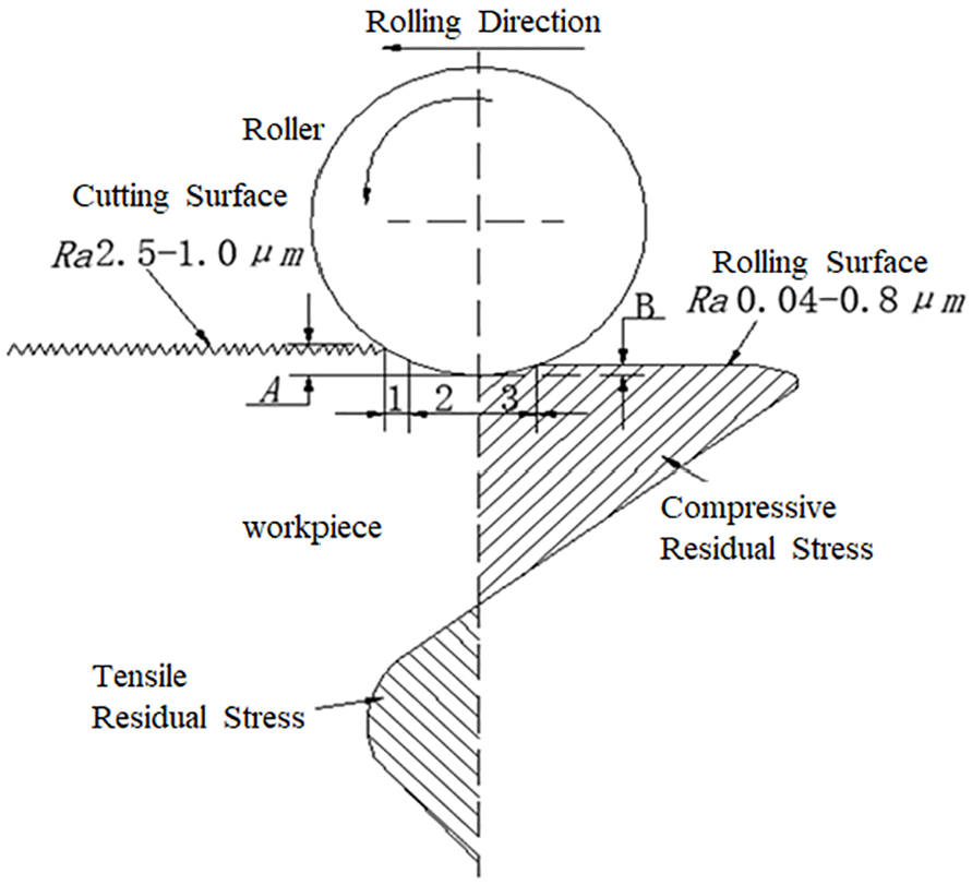
Principle of rolling processing. 1 – Pressed-in area, 2 – Plastic deformation area, 3 – Elastic recovery area. A – Interference, B – Elastic recovery amount.
Rolling processing technology, with its remarkable characteristics of high efficiency, environmental friendliness, and energy conservation, has demonstrated immense application potential and broad development prospects in the manufacturing industry. As technology advances rapidly and manufacturing processes continue to refine, this technology has been successfully applied in hydraulic transmission and the automotive industry, significantly enhancing the processing efficiency and quality of precision workpieces such as hydraulic cylinder bores and sliding shaft surfaces. 4 However, due to current technological limitations, rolling processing technology is primarily utilized for the machining of workpiece external surfaces and shallow hole walls (l/d ≤ 10), with relatively limited application in deep hole (l/d ≥ 10) wall processing, necessitating further technological breakthroughs and expansions.
Currently, research on rolling processing technology remains focused on the finishing and strengthening of workpiece external surfaces. Yang conducted experimental designs on the rolling strengthening of single-cylinder diesel engine crankshafts, optimized processing parameters, and verified them in actual production, revealing that rolling processing significantly improves the surface roughness and performance of crankshafts. 5 Dweiri et al. analyzed the influence of interference fit, rolling passes, and roller diameter on non-ferrous metallic materials, emphasizing the surface roughness and strengthening effects, and optimized the rolling processing parameters for non-ferrous metals to further enhance surface roughness. 6
With the rapid advancements in computer software technology, finite element simulation technology has been widely applied in the field of elastoplastic deformation, providing robust data support and simulation tools for in-depth studies of complex physical processes such as cold plastic deformation mechanisms and drawing tests. The Altan team utilized DEFORM software to establish both two-dimensional and three-dimensional models to investigate the rolling process, revealing the force characteristics of single-roller rolling in the three-dimensional simulation and pointing out that the surface roughness achieved by single-roller processing is inferior to that of multi-roller processing. 7 A comprehensive and systematic research framework for deep hole rolling processing has yet to be established, and current practices primarily rely on the introduction of international advanced technologies and tools, with parameter settings referenced for executing precision deep hole processing.
To address the issue of low efficiency in deep hole precision processing, this study aims to introduce rolling processing technology into the field of deep hole processing as an effective supplement and partial alternative to traditional grinding processes. Through a comprehensive approach combining theoretical analysis and experimental validation, this study takes the precision processing of the inner bore of a 42CrMo alloy steel boring machine support shaft as a typical case, striving to explore and determine the optimal combination of deep hole rolling process parameters. The specific research process is illustrated in Figure 2 below. In this process, the universal laws governing the influence of deep hole rolling process parameters on surface roughness will be deeply revealed, aiming to significantly enhance processing efficiency while laying a solid practical foundation and theoretical guidance for the widespread application of deep hole rolling production in the future.

Research flowchart.
Constructing elastoplastic equations
Elastoplastic deformation problems, due to their nonlinear characteristics, encompass the complex interaction of elastic and plastic deformations, making it difficult to directly describe with an accurate mathematical model. Therefore, when analyzing such problems, it is necessary to set up a deformation environment and constraint conditions that reflect the actual elastoplastic characteristics, while simplifying the complexity of the problem to build an effective mathematical model. This model can reveal the relationship between stress, strain, and displacement, and can serve as the basis for finite element simulations. Using the constitutive equation and flow-plastic stress equation, one can guide the parameter settings in finite element simulations to ensure the validity of the model.
Basic assumptions of elastoplastic mechanics
In solving elastoplastic mechanics problems, the following auxiliary assumptions are usually introduced to reduce the complexity of the problem and improve the accuracy of the solution:
(1) Continuity assumption: It is assumed that the object is composed of continuous and orderly points without gaps between them. When the object undergoes deformation, these points also change continuously accordingly to maintain close contact between all points inside the object.
(2) Uniformity assumption: It is assumed that all points of the object remain unchanged in their physical properties during displacement and deformation.
(3) Isotropy assumption: It is believed that the mechanical properties of any point in the object are the same along different directions.
(4) Small deformation assumption: When the overall deformation of the object is very small, it can be regarded as a small deformation.
(5) Time-independence assumption: It is assumed that all points of the object move synchronously during displacement and deformation, that is, the strain rate has no effect on the material behavior.
(6) Linear elasticity assumption: If the workpiece only undergoes elastic deformation under external forces, there is a linear relationship between stress and strain.
Basic equations of elastoplastic mechanics
Based on the key principles of static equilibrium and deformation compatibility, corresponding equilibrium equations and compatibility equations can be derived. Combined with the elastoplastic constitutive equation, these three sets of equations form the basic equation system for solving elastoplastic mechanics problems.
Equilibrium equation
The stress distribution of an object at a random point
Choose an arbitrary infinitesimal body in the object. As shown in Figure 3, let

Stress components.
Only the stress in the


After rearranging the above equation, we get:

Similarly, from the balance in the direction and the balance in the direction, we obtain:

Geometric equation
In order to describe the deformation of a point in detail, a symmetric second-order strain tensor is added, which is defined as the strain tensor ε.
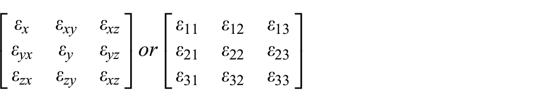
In the Cartesian coordinate system, let


From equation (5), it can be seen that only six of the nine strain components are independent. Analyze these six independent components.
The physical meaning of εx, εy, εz
As shown in Figure 4, take a small segment

Define

Therefore, it can be concluded that

Deformation view.
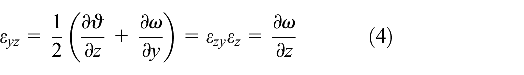
The physical meaning of
In the
Let
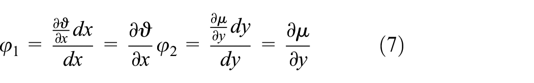
Then


Let

Since

It has been verified that
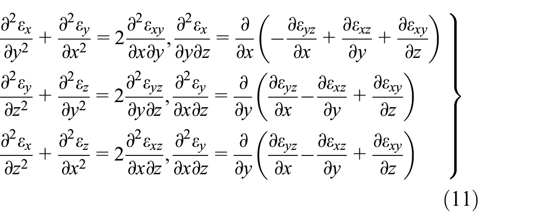
Geometric equation
The deformation compatibility requires that under the action of external forces, the displacements of all points in the object remain continuous. Equation (4) reveals the linear relationship between the six strain components at any point in the object.
Constitutive equation
The magnitude of the force exerted on an object determines the type of strain that occurs, hence the constitutive equation that governs the behavior varies depending on whether the deformation is elastic or plastic.
Elastic constitutive equation
Since the supporting shaft is made of elastic linear material, the stress state at any point is determined by the corresponding strain state. This leads to a linear relationship between stress and strain, represented as

Plastic constitutive equation
The determination of whether a material undergoes plastic deformation is based on its yield strength, and the analysis of stress distribution utilizes the loading theory. In the plastic state, the stress and strain of a point follow the plastic constitutive equation, which is based on the deformation criterion and adopts the plastic incremental theory.
First, the yield surface needs to be determined. The yield surface is a curved surface that represents the yield condition in the stress space. The yield surface is related to stress, strain, time, temperature, and other factors. Its expression is shown in equation (14).

The Tresca criterion postulates that a material will yield when the maximum shear stress reaches a certain limit. Therefore, the mathematical expression of the Tresca criterion is:

The Tresca yield surface is composed of three pairs of parallel planes, perpendicular to the

The intersection line of the yield.
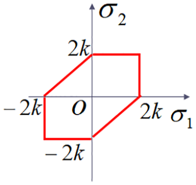
From this, we can obtain the geometric form of the Tresca criterion:
(1)
(2)
(3)
Secondly, assuming that 42CrMo alloy steel is an ideally elastic-plastic material, its yield surface coincides with the failure surface. If 42CrMo alloy steel undergoes plastic deformation, hardening occurs simultaneously on the material surface, forming a new yield surface.
The expression of the yield function is:
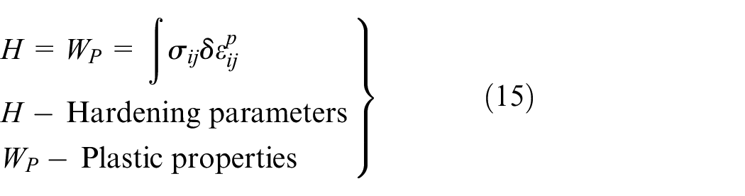
Finally, the interrelationship between the components of plastic strain increment is determined, along with the flow rule. The flow rule stipulates that the plastic strain increment at any point

Assuming that the plastic potential surface passing through any point

The plastic strain increment at point

The establishment of the three major theoretical equations completes the establishment of the elastic-plastic mathematical model, establishing the relationship between stress, strain, and displacement. This model and its constitutive equation are applied in finite element simulations, providing a basis for setting the fluid-plastic stress equation and configuring simulation processing parameters.
Deep hole rolling process finite element analysis
Deform 3D software, designed specifically for simulating cutting and cold rolling processes, is also very suitable for performing rolling process simulation analysis. Therefore, this study uses Deform 3D to simulate the deep hole rolling process, effectively analyzing the stress and strain conditions on the workpiece surface, providing an effective analytical method for deep hole rolling process research.
Establishment of finite element simulation model
Assumptions for finite element simulation
In finite element simulation, to ensure the accuracy of the results and reduce the amount of calculation, the following assumptions are made:
(1) It is assumed that the 42CrMo alloy steel material exhibits isotropic properties during deformation;
(2) It is assumed that only elastic-plastic deformation occurs in the finite element model;
(3) The rollers are considered rigid-plastic bodies, and their elastic deformation is ignored.
Construction of finite element simulation model
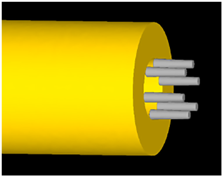
In the simulation model, the actual processing was simplified. Quenched and tempered 42CrMo alloy steel was selected as the workpiece material, with an outer diameter of Φ60 mm, a wall thickness of 15 mm, a length of 300 mm, and an inner hole size adjusted according to experimental requirements. After simplification of the rolling tool, the support structure was removed, leaving a circular ring with a diameter of 30 mm composed of six evenly distributed rollers, with detailed roller parameters shown in Figure 7. The modeling was done using UG NX11.0 and imported into the Deform 3D software to establish a finite element model, as shown in Figure 8.

Roller dimensions.
Three-dimensional model of workpiece and die.
Mesh generation was performed on the simulation model, and boundary conditions, rotational speed, direction, feed speed, and direction of the rolling head were set for the workpiece. The contact relationship between the workpiece and the rolling head was defined, and the rheological stress equation for the simulation was set according to the elastic-plastic mechanics equations. After completing all the preprocessing, the BD file was saved and generated, representing the flow stress equation, which is similar to the one shown in Figure 9.
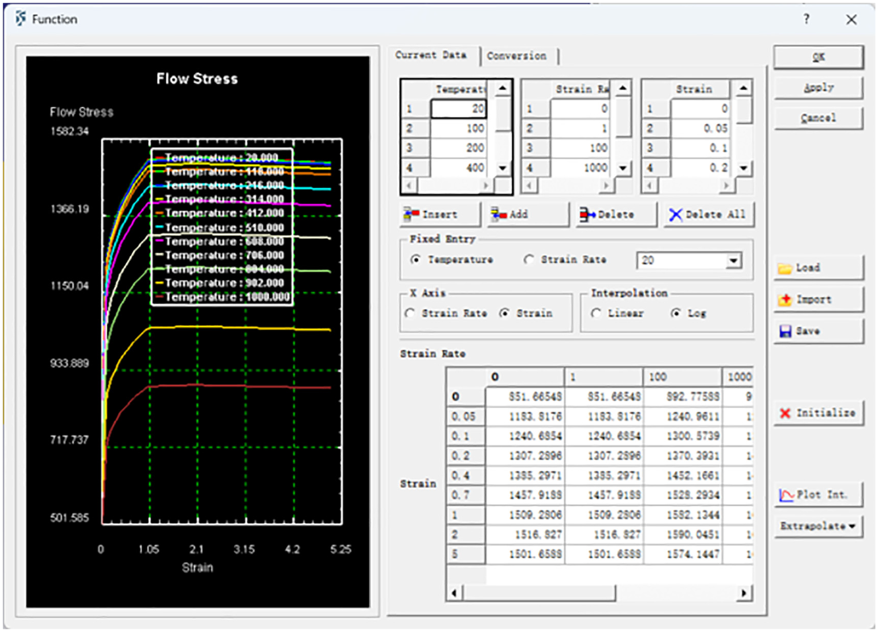
Setting the flow stress equation.
Validation of accuracy of finite element simulation model
The accuracy of the simulation model and the predicted results was verified through experiments. Since conventional stress detection equipment cannot directly measure the inner hole surface, direct comparison with experimental data was not possible. Therefore, the change in inner hole surface roughness was predicted through simulation and compared with experimental results. If they were consistent, the model was confirmed to be accurate and the simulation was settled; if they were inconsistent, the simulation model was adjusted.
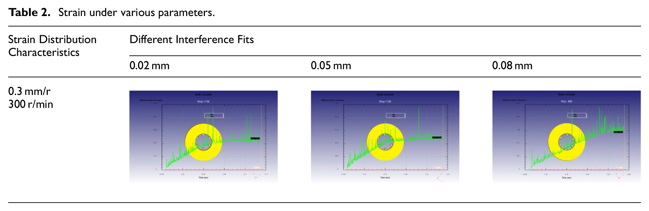
By consulting the machining manual and professionals, the parameter range for processing a Φ30 mm inner hole in 42CrMo alloy steel was determined, with an interference of 0.02–0.10 mm, a rotational speed of 200–500 r/min, and a feed rate of 0.1–0.4 mm/r. Experiments were conducted with an interference of 0.03, 0.05, and 0.08 mm, a rotational speed of 300 r/min, and a feed rate of 0.3 r/min. The analysis of the simulation results is shown in Tables 1 to 4 below.
Stress under various parameters.

Strain under various parameters.
Predicted results.

Measured results.

Based on the physical properties of 42CrMo alloy steel, which has a yield strength (MPa) of ≥930 MPa indicating that the material begins to undergo plastic deformation when the maximum stress exceeds 930 MPa, and an ultimate tensile strength (MPa) of ≥1100 MPa indicating that failure or fracture may occur when the maximum stress exceeds 1100 MPa, the following inferences can be made:
(1) When the maximum stress output from the finite element simulation is less than 930 MPa, the workpiece surface undergoes elastic deformation, and the surface quality remains unchanged.
(2) When the maximum stress output from the finite element simulation is greater than 930 MPa but less than 1100 MPa, the workpiece surface undergoes plastic deformation, and the surface quality improves.
(3) When the maximum stress output from the finite element simulation is greater than 1100 MPa, the workpiece surface is damaged, and the quality declines.
Based on these inferences, predictions of the simulation results are provided in Table 3
Based on the experimental parameters, the rolling process was carried out, and the measurements are shown in the table below.
By comparing the results from Tables 3 and 4, it can be concluded that the experimental results are in line with the simulation predictions, verifying the accuracy of the inferences. This also demonstrates the accuracy of the simulation model and the elastic-plastic model.
Designing the experimental plan
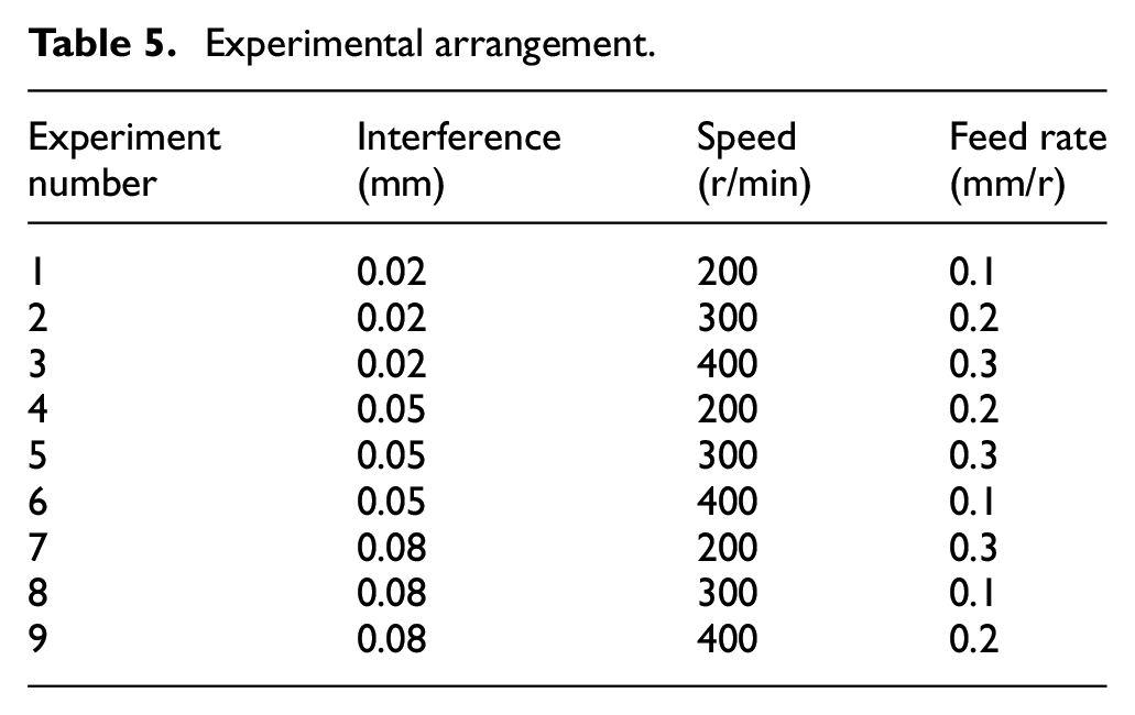
This finite element simulation experiment uses an orthogonal experimental design, selecting three factors: interference (0.02, 0.05, 0.08 mm), rotational speed (200, 300, 400 r/min), and feed rate (0.1, 0.2, 0.3 mm/r), forming an experimental plan with three factors and three levels (Table 5).
Experimental arrangement.
Output experimental results and analysis
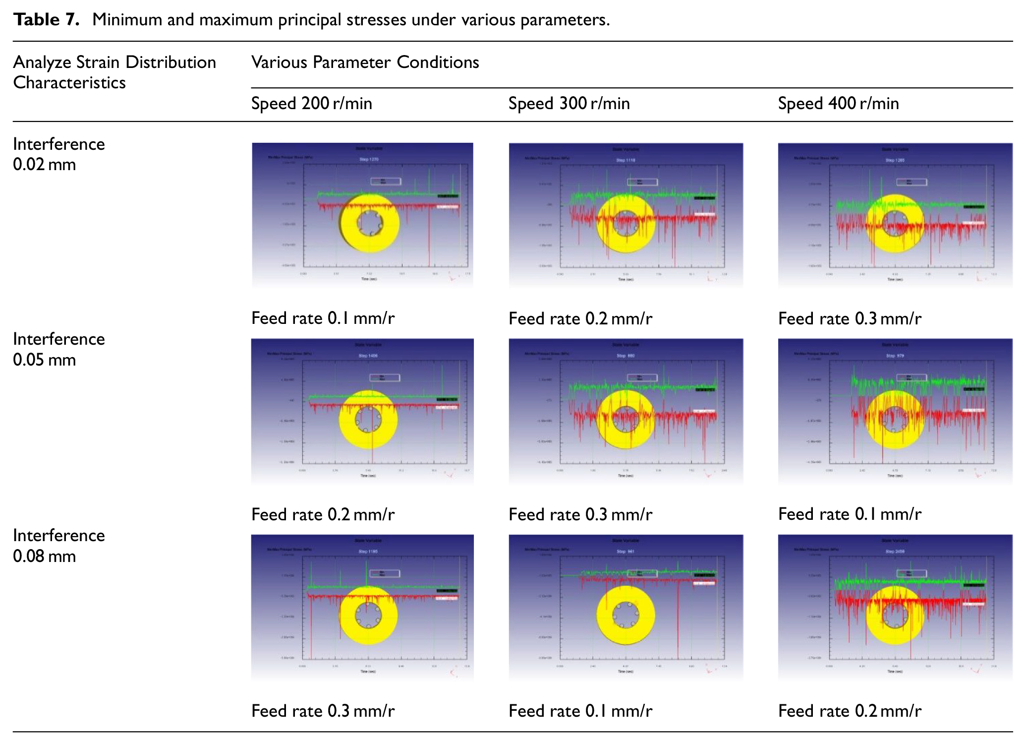
After completing a series of simulation processes, we performed a detailed post-processing analysis of the results. To accurately assess the maximum stress and deformation capability of the workpiece during processing, we specifically selected the minimum and maximum principal stresses, as well as the equivalent strain, as key output parameters for in-depth study. Through nine experiments, we obtained specific data for these key parameters and have compiled and summarized the results in Tables 6 and 7.
Equivalent stress under various parameters.

Minimum and maximum principal stresses under various parameters.
After studying the impact of various parameters in Table 6 on strain, it is found that feed rate and rotational speed have a significant effect on the smooth change of strain. A moderate increase in feed rate and rotational speed helps the strain reach a stable state quickly, while the interference fit has a relatively small impact. A smaller range of strain change is beneficial to improving the precision of the inner hole surface of the workpiece.
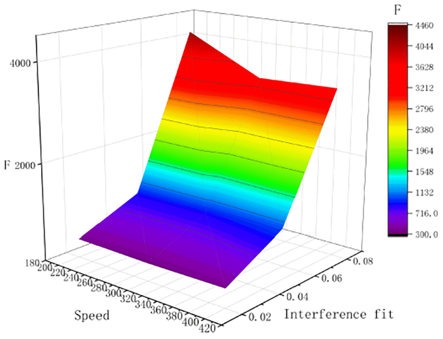
After conducting a statistical analysis of Table 7, it is found that the feed rate and rotational speed have a relatively small impact on stress, while the interference fit has a significant influence. When the interference fit is 0.02, the maximum principal stress ranges from 360 to 430 MPa; at 0.05, it ranges from 920 to 1050 MPa; and at 0.08, it reaches 3520 to 4430 MPa. To further investigate the influence pattern of various parameters on the maximum stress, a surface plot depicting the impact of each parameter on the maximum stress has been drawn and analyzed, as shown in Figures 10 to 12.

The impact of interference fit and feed rate on maximum stress.
The impact of interference fit and rotational speed on maximum stress.

The impact of feed rate and rotational speed on maximum stress.
Based on the curved surface variation depicted in Figure 10, which illustrates the impact of interference fit and feed rate on maximum stress, it is evident that interference fit has the most significant influence on maximum stress, with feed rate being a secondary factor. As the interference fit increases, the maximum stress also rises. Simultaneously, as the feed rate increases, the surface quality of the workpiece initially improves and then stabilizes.
Based on the curved surface variation depicted in Figure 11, which shows the impact of interference fit and rotational speed on maximum stress, it is evident that the influence of interference fit on maximum stress is the most significant, with rotational speed being the secondary factor. As the interference fit increases, the maximum stress also increases. Meanwhile, as the rotational speed increases, the surface quality of the workpiece first improves and then tends to stabilize.
Based on the curved surface variation depicted in Figure 12, which shows the impact of feed rate and rotational speed on maximum stress, it is evident that neither the feed rate nor the rotational speed has a significant influence on the maximum stress.
After studying the impact of various parameters on maximum stress as depicted in Figures 10 to 12, it has been found that the interference fit has the most significant effect on the maximum stress. To ensure the safety of rolling processing and prevent damage to the rolling head or workpiece caused by excessive maximum stress, a maximum stress prediction model has been established through the method of polynomial fitting. Specifically, it is as follows:

Based on the results of the finite element analysis, the parameter range suitable for deep hole processing was determined to ensure experimental safety and accuracy. Considering that the yield strength of 42CrMo alloy steel is between 930 and 1100 MPa, when the interference is 0.045 mm, the stress is 847 MPa, and when it is 0.055 mm, it is 1393 MPa, so an interference of 0.045, 0.05, and 0.055 mm was chosen for the experiment. At the same time, in order to promote the rapid stabilization of strain, the feed rate and rotational speed were appropriately increased, selecting 0.2, 0.3, 0.4 mm/r, and 260, 340, 420 r/min respectively.
Deep hole rolling process experiment
The support shaft is a core component of large-scale floor boring machines, with the inner hole of the support shaft installed to connect the shaft, providing support and fixing for the connecting shaft. The support shaft is 1500 mm long, with an outer diameter of Φ60 mm, an inner hole of Φ30 mm, and an inner hole surface roughness within 0.4 μm. The material of the support shaft is 42CrMo alloy steel.
Deep hole rolling process experiment plan
The experiment focuses on exploring the impact of processing parameters on surface roughness, without involving roundness and straightness. Based on the simulation results, an orthogonal experimental method was adopted to formulate the experimental plan, with detailed parameters shown in Table 8.
Rolling processing parameters.

Building the experimental platform
The deep hole rolling process experimental platform is mainly composed of a machine tool, a four-claw chuck, a sealing oil device, a dial indicator, a center stand, a guide sleeve, a center pin, a rolling head, a tool rod, a tool rod support frame, an oil pump, and a cooling box. Figure 13 shows the completed experimental platform, and Table 9 lists the processing parameter range of the platform.

Completed experimental platform setup. 1 – Four-claw chuck, 2 – Sealing oil device, 3 – Dial indicator, 4 – Center stand, 5 – Guide sleeve, 6 – Center pin, 7 – Tool rod, 8 – Tool rod support frame.
Machining parameters of the experimental platform.

In the experiment, the workpiece needs to undergo rough turning of the outer diameter and drilling procedures to achieve an inner hole surface roughness of Ra 0.8–1.6 μm. Select a rolling head with adjustable dimensions, and adjust it after measuring the inner hole size to meet the interference requirements. The material of the rollers is GCr15, with a hardness of 55–60 HRC after heat treatment. Relevant workpieces and tools are shown in Figure 14.

Workpiece to be Processed and Rolling Tool.
Rolling process and detection
Rolling process
Based on the experimental plan and the built experimental platform, during the rolling process, an oil-based coolant was used to control the temperature and reduce friction, thereby improving the surface roughness of the workpiece. The specific process is shown in Figure 15.

Rolling process.
Workpiece detection
To ensure accurate measurement of the inner hole surface roughness, the workpiece needs to be cut. In deep hole processing, the accuracy of the tool exit position is lower than that of the starting position, so the 200 region at this position is selected as the measurement segment. After being cut off by the cutting machine, the workpiece is split in the middle by wire cutting to expose the inner hole surface. Figure 16 shows the workpiece after partial cutting.
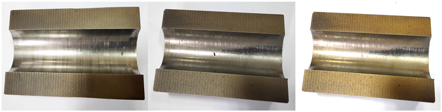
Cut workpiece.
The workpiece inner hole surface was measured using a stylus-type surface roughness measuring instrument, and the measurement results are shown in Table 10.
Measurement results.

After data processing, Figure 17 compares the surface roughness of the workpiece before and after processing. The results show that the surface quality of the workpiece is improved overall after rolling processing, and there is no occurrence of the “necking” phenomenon. This proves that the established simulation model and stress prediction model are accurate.

Comparison of inner hole surface roughness of workpiece before and after processing.
Based on the measurement data, Figure 18 shows the relationship between various parameters and the inner hole surface roughness to explore the influence law of these parameters on surface roughness.

The influence of interference fit and feed rate on Ra.
Based on the surface variation depicted in Figure 18 regarding the influence of interference fit and feed speed on Ra, it is evident that the interference fit has the most significant impact on surface roughness, followed by the feed speed. As the interference fit increases, the surface quality of the workpiece improves. However, as the feed speed increases, the surface quality of the workpiece first improves and then decreases slightly.
Based on the surface variation depicted in Figure 19 regarding the influence of interference fit and rotational speed on Ra, it is apparent that the interference fit has the most significant impact on surface roughness, with rotational speed being the second most influential factor. As the interference fit increases, the surface quality of the workpiece improves. However, as the rotational speed increases, the surface quality of the workpiece first improves and then declines significantly.

The influence of interference fit and rotational speed on Ra.
Based on the surface variation depicted in Figure 20 regarding the influence of rotational speed and feed speed on Ra, it is observed that feed speed has the most significant impact on surface roughness, followed by rotational speed. As both the rotational speed and feed speed increase, the surface quality of the workpiece initially improves and then declines.

The influence of rotational speed and feed speed on Ra.
According to the experimental measurements, it was found that when the interference fit is 0.055 mm, the rotational speed is 340 r/min, and the feed speed is 0.3 mm/r, the surface roughness is optimal. However, this combination does not necessarily represent the optimal parameter set. Therefore, based on the experimental measurement data, we will utilize scientific methods to determine the optimal parameter combination.
Parameter optimization
Analysis of variance
After conducting a variance analysis on the experimental measurement results, we have determined the optimal parameter combination from the experimental data and clarified the significant order of the influence of each parameter on surface roughness.
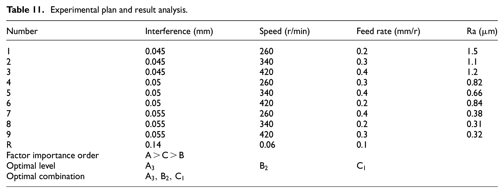
As shown in Table 11, the significant order of factors affecting surface roughness is in descending order: interference fit, feed rate, and rotational speed. This finding is consistent with the analysis results presented in Section “Rolling process and detection.” The optimal parameter combination in this experimental scheme is A3, B2, C1 specifically referring to an interference fit of 0.055 mm, a rotational speed of 340 r/min, and a feed rate of 0.2 mm/r. Under these conditions, the precision of rolling processing achieves the highest level.
Experimental plan and result analysis.
Parameter optimization using MATLAB
The general mathematical expression of surface roughness Ra is as follows:

For deep hole processing, optimization is needed to reduce the processing parameters. The optimization results are as follows:

In the formula:
The relationship between each process parameter and surface roughness

Let

In MATLAB, program the nine sets of experimental data, perform fitting operations, and output the calculation results:

Perform variance analysis and testing on the fitting function, and calculate p = 0.034,
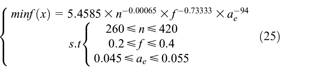
Based on the actual parameter range of deep hole processing, establish a constraint function and then construct a multi-objective optimization function model:
In MATLAB, use the fmincon function to solve the equation through the objective function and constraint conditions, and finally obtain n = 364 r/min, f = 0.3471 mm/r,
Experimental verification and comparison
According to the parameters obtained from the optimization calculation, experiments were conducted and the results were evaluated using the established measurement method. The experiments showed that the inner hole surface roughness decreased to 0.22 μm, which is lower than the previous measurement value, confirming the effectiveness of the optimized parameters.
Grinding processing was performed under the same material conditions, and the inner hole surface roughness of the workpiece treated by honing and lapping reached 0.13 μm, which is better than the result of rolling processing. However, the grinding processing time is 10 times that of rolling processing. The specific comparison data is shown in Table 12.
Experiment plan and result analysis.

The experimental results show that rolling processing has advantages in terms of accuracy and efficiency. However, the rolling processing technology has higher requirements for the initial surface roughness of the inner hole of the workpiece, and the selection of processing parameters has certain difficulties; its processing accuracy is also lower than that of grinding processing. Despite these limitations, rolling processing can still replace most grinding processing for deep hole finishing, thereby effectively improving processing efficiency.
Conclusion
This study combines theory and practice to explore the application of rolling processing technology in deep hole processing. By constructing an elastic-plastic equation, the relationship between stress, strain, and displacement is revealed, which can serve as the basis for finite element simulation. A finite element simulation model is established and its accuracy is verified. By analyzing the simulation results, the equation of the relationship between interference and stress is fitted, and the reasonable range of interference is determined, providing a basis for setting experimental parameters.
Taking the boring machine support shaft as the experimental object, a processing experimental platform was built. The analysis of the test results shows that the inner hole surface roughness increases with the increase of interference, and reaches the best at a feed rate of 0.3 mm/r and a rotational speed of 340 r/min, further increasing the parameter values will lead to a decrease in accuracy. Variance analysis determines that interference has the most significant impact on surface roughness, followed by feed rate and rotational speed, and the optimal combination of parameters is screened out as interference of 0.055 mm, rotational speed of 340 r/min, and feed rate of 0.2 mm/r. The surface roughness equation is fitted using MATLAB, and its significance is verified through variance analysis. Based on this, a multi-objective optimization function model is constructed and solved, and the final calculation is n = 364 r/min, f = 0.3471 mm/r,
This paper has successfully applied rolling processing technology to the field of deep-hole machining, achieving remarkable progress in addressing the challenge of low efficiency in deep-hole finishing. However, this represents merely the initial stage of our exploration journey in deep-hole processing technology, as vast unknown territories still await our discovery and research. Looking ahead, we can build upon and refine the research methods presented in this paper to further investigate how factors such as the structural design of rolling tools, their quantity allocation, and the selection of coolant types affect surface roughness. By doing so, we can continuously optimize process parameters to improve the efficiency and precision of deep-hole finishing. Furthermore, by enhancing existing optimization algorithms to increase their convergence speed and accuracy, we will be able to more precisely identify the optimal parameter combinations, thereby opening up new avenues for the continuous advancement and widerspread application of deep-hole processing technology.
Footnotes
Handling Editor: Divyam Semwal
Author contributions
Tian Chunlei: performed the data analyses and wrote the manuscript; Cao Yan: contributed to the conception of the study; Chen Tian: contributed significantly to analysis and manuscript preparation; Yuan Tianlong: directed the experiment.
Declaration of conflicting interests
The author(s) declared no potential conflicts of interest with respect to the research, authorship, and/or publication of this article.
Funding
The author(s) disclosed receipt of the following financial support for the research, authorship, and/or publication of this article: This research was funded by National Natural Science Foundation of China (Grant: 52275508), Shaanxi Province Bearing Digital Design and Testing Technology Innovation Service Platform (2022PT-02).
Consent to participate
The authors declare that they all consent to participate in this research.
Consent for publication
The authors declare that they all consent to the publication of this manuscript.