
Abstract
To investigate the influence of the flow channel’s width-to-narrow ratio on the Tesla valve’s flow characteristics, this paper establishes five Tesla valve models with different width-to-narrow ratios. Employing the laminar flow model, CFD methods were used to numerically simulate both the forward and reverse flows through the Tesla valve across a spectrum of width-to-narrow ratios, ranging from 0.2 to 1. The results reveal the flow trends in the straight or arc channels show opposite variation patterns when flowing in forward and reverse directions. The flow rate passing through straight channel is more sensitive to the response of a small width-to-narrow ratio. Irrespective of the flow direction, as the width-to-narrow ratio increases, the fluid flow within the valve demonstrates increasingly pronounced stratification. The pressure curve of the diversion section assumes an “∞” shape in forward flow, whereas in reverse flow, it assumes a “flat plate” shape.
Introduction
Tesla valves are often widely used in fluid control applications, which do not contain any moving parts, and the special structure makes the forward and reverse flow present different flow characteristics, thus controlling the fluid flow. 1 Generally, the forward pressure drop is much less than the reverse pressure drop. As a result of this difference in differential pressure characteristics, the flow through varies to varying degrees.
At present, a number of scholars have studied the flow characteristics, heat transfer characteristics, and other aspects of the Tesla valves by numerical simulation or experiment. Mohammadzadeh et al. analyzed the influence of Tesla microvalve (TMV) stage and Reynolds number on the valve’s performance, simulating and comparing unsteady and steady flow in the valve. 2 Raffel et al. experimentally investigated the effects of flow direction and Reynolds number on the flow phenomena. 3 Thompson et al. varied the stage number, the distance between the valves, and the Reynolds number to investigate the influence on the diodicity. 4 Hu et al. investigated the effect of angle on a single-stage Tesla valve and found that the diodicity of the valve is more significant at an angle of 70°–80°. 5 Chada and Akella investigated the effect of angle on a multistage Tesla valve and found that for the same flow rate, the pressure required for reverse flow is significantly higher than that for forward flow. 6 Liu et al. investigated a Tesla valve-pipe system model’s fluid flow and pressure drop. It was found that the unidirectional flow performance of Tesla valves gets better with symmetry. 7 Qian et al. studied Al2O3-water nanofluids in forward and reverse flow in a micro-scale T45-R type Tesla valve. 8 Liosis et al. simulated the flow of Fe3O4 nanoflow in the forward flow of a Tesla valve, and investigated the particle distribution and mixing efficiency at different inlet velocities. 9 Yontar et al. investigated the variation of gas velocity in a Tesla valve structure with 11 flow control sections for methane and the fluid flow characteristics numerically in forward and reverse flow at laminar and turbulent velocities. 10 De Vries et al. proposed a novel Tesla valve to facilitate circulation and improve thermal resistance in pulsating heat pipes and experimentally tested its functionality and disability. 11 Menon et al. found that surface heating will increase the diodicity of vertically mounted Tesla valves. 12 Qian et al. analyzed the number of Tesla valve stages and the pressure ratio between the inlet and outlet to investigate the possibility of aerodynamic noise and energy loss and assessed Mach number, turbulent dissipation rate, and exergy loss as criteria.13,14 Monika et al. proposed and numerically studied a liquid cooling plate in a Tesla valve configuration to provide a viable technique for battery pack cooling. 15
In addition to above, utilizing the characteristics of Tesla valves, quite a number of researchers have also studied the applications of Tesla valves in several fields. Dennai et al. focused on the effect of the internal length of the Tesla valve on efficiency while addressing the issue of micro-injectors. 16 Jin et al. explored the effect of structural parameters on performance over a wide range of inlet velocities to provide a reference for the further application of Tesla valves in hydrogen pressure reduction for hydrogen fuel cell electric vehicles. 17 Cao et al. proposed a new fluid diode plate based on the Tesla valve without moving parts. They verified the model’s effectiveness under different influencing factors through experiments and numerical simulations. 18 Wu et al. proposed a Tesla-type orifice plate structure with higher pressure drop performance than a standard orifice plate, providing a viable technical structure for achieving efficient hydrogen pressure reduction in hydrogen fuel cell vehicles. 19 Li et al. have improved and optimized the Tesla-type orifice plate structure and the pressure reduction performance. 20 Wang et al. designed an innovative mixer based on the Tesla valve and discussed the geometrical parameter effect, aspect ratio effect, and Reynolds number effect. The optimum combination of geometrical parameters for the Tesla valve-type micro-mixer with low-pressure drop and high mixing performance at a low Reynolds number was obtained. 21 Wang and Chen investigated the effect of the diversion port spacing and bending spacing on the mixing efficiency and the pressure drop of the Tesla valved mixer, and the optimum parameter sizes were found. 22 Lai et al. proposed a thermal management system of batteries based on Tesla valves and coupled battery cold plate simulation to investigate the effects of the position of cold plate and channel parameters. The results showed that the side cooling has better thermal performance than the main surface cooling. 23 Zhang et al. proposed a new multistage pressure-reducing valve based on the Tesla-type orifice valve, which can provide safer and more effective pressure reduction under complex conditions. 24
In summary, there has been a substantial body of research conducted on the characteristics of Tesla valves. However, most researches have been based on the variation of fluid type and properties with respect to the geometrical parameters of the Tesla valve, and the differences in performance due to variations in a particular geometrical parameter have yet to be dealt with in depth. Therefore, five models of Tesla valves with different width-to-narrow ratios of the flow channel were developed, and numerical laminar flow calculations were carried out to obtain the performance effects caused by changes in the width-to-narrow ratio with the help of CFD technology.25–27
Physical models and calculation method
Physical models
The calculation model in this paper is a micro-scale T45-R type Tesla valve, featuring the structure depicted in Figure 1 in µm. As illustrated, the inflow from the right end in Figure 1 is forward flow, that is, the fluid flows through the straight channel with less resistance to flow. Conversely, the inflow from the left end is reverse flow, that is, the fluid flows from an inclined channel with high resistance to flow. Figure 2 shows the 3D model of the Tesla valve, and different Tesla valves can be gotten by changing h. Figure 3 shows the arc and straight channels through which the fluid flows in this paper. The width-to-narrow ratio α is defined as follows, where H = 100 μm.


Tesla model (unit: μm).

Three-dimensional model.

Arc and straight channels.
Calculation method
The flow sections of calculation models in this paper are all non-circular, so the hydraulic diameter 28 is

where A is the area of flow section, and X is the wet perimeter.
According to the equation of Reynolds number 28

where u is the velocity of the inlet;
In this paper, the maximum calculation flow rate

Clearly, the smaller the wet perimeter, the larger the Reynolds number. The maximum Reynolds number occurs at α = 0.2,

The fluid flow state at each flow rate is laminar.
For the maximum calculation velocity


It shows that the larger the width-to-narrow ratio, the larger the Reynolds number. The maximum Reynolds number occurs at α = 1.0,

The fluid flow state is laminar at all flow velocity, so the fluid flow state under all the calculation schemes is laminar. Numerical calculations of flow in Tesla valve were carried out in this paper based on ANSYS FLUENT 19.2. The control equations 30 to be solved are

Due to the simple model structure used in this study, the structured mesh was used to discretize the geometric model. The number of calculated meshes for the Tesla valve model corresponding to the five cases of width-to-narrow ratios of 0.2, 0.4, 0.6, 0.8, and 1.0 is 216,960, 408,925, 601,680, 808,122, and 1,042,470, respectively. The calculation meshes of the Tesla valve at α = 1.0 are shown in Figure 4. Based on calculated experience, this mesh number is sufficient for microchannels. 8 The flow medium is liquid water, and the three-dimensional double-precision solver is used for the solution. Set the inlet boundary to the velocity-inlet, which can be determined according to flow rate and cross-sectional overflow area. Set the outlet boundary to the pressure-out, which flows directly into the atmosphere. Set the wall to the no-slip boundary condition and set the roughness constant to 0.5. The discrete equations are solved using the Coupled. For spatial discretization, the gradient is chosen to be least squares cell based, the pressure is chosen to be second order, and the momentum is chosen to be second order upwind. The convergence residuals were all set to 10−4, and the relaxation factors settings in iterative calculations are shown in Table 1.

The calculation meshes of the Tesla valve at α = 1.0.
Relaxation factors settings.

Analysis of results
Calculation validation
Four calculation models and corresponding calculation method in the literature 31 were used in this paper for calculation validation. The calculation models are shown in Table 2, and the results comparison is shown in Table 3. As shown in Table 3, the maximum relative error between the calculated and experimental values is −8.11% and the minimum error is 3.33%, the numerical calculation is reliable.
Calculation models.

Comparison of pressure drops.

Flow-through capacity
In scenarios of forward or reverse flow, a portion of fluid flows through the arc channel and some through the straight channel. The disparity in flow resistance leads to a difference in the flow-through capacity of the two. To investigate the flow distribution percentages of two channels under different flow scenarios, numerical calculations were conducted for forward and reverse flows under inlet flow rates ranging from 1 to 8 mL/min, and the results are shown in Figure 5.

Percentage of flow distribution for different width-to-narrow ratio scenarios (left: forward flow; right: reverse flow): (a) α = 0.2, (b) α = 0.4, (c) α = 0.6, (d) α = 0.8, and (e) α = 1.0.
For forward flow, the flow rate passing the straight channel tends to increase as the flow rate increases, but the flow rate passing the arc channel tends to decrease gradually. For α = 0.2, as the total flow rate increases from 1 to 8 mL/min, the percentage of flow rate passing the straight channel rises from 67.46% to 88.77%, while the percentage of flow rate passing the corresponding arc channel drops from 32.54% to 11.23%. For reverse flow, the flow rate passing the straight channel tends to decrease as the flow rate increases, while the flow rate passing the arc channel tends to increase. For α = 0.4, as the total flow rate rises from 1 to 8 mL/min, the percentage of flow rate passing the straight channel drops from 54.73% to 33.30%, while the corresponding percentage of flow rate passing the arc channel rises from 45.27% to 66.70%. Combined, as the total flow rate increases, the trend of the flow rate allocated within the straight or arc channel shows precisely the opposite pattern of change for forward and reverse flows.
Furthermore, for the five width-to-narrow ratio conditions, the minimum percentage of flow rate passing the straight channel is 67.46%, 74.10%, 77.48%, 78.79%, and 79.08% for forward flow, while the maximum percentage of flow rate passing the straight channel is 54.73%, 49.16%, 46.03%, 44.26%, and 43.37% for reverse flow. Obviously, for any given α, the flow rate passing the straight channel for forward flow will always be more than the flow rate passing for reverse flow. In other words, the flow rate passing the arc channel for forward flow will always be less than the flow rate passing for reverse flow. That’s why it is said that the Tesla valve achieves flow control through this characteristic. At the same time, with increasing α, the flow rate passing the straight channel shows a gradual increase for forward flow, while the reverse flow shows a gradual decrease; the arc channel follows an exactly opposite trend.
It was also found that for any given flow rate scenario, the percentage of flow rate passing the straight channel tends to rise initially more sharply and then more gradually as α gets larger for forward flow. In other words, when α is small, the flow rate passing the straight channel changes more rapidly, that is, the response is more sensitive to α. In contrast, when α is large, the flow rate passing the straight channel changes more slowly, that is, the response is not sensitive to α.
For α = 0.6, as the total flow rate varies from 1 to 8 mL/min, the percentage of flow rate passing the straight channel is 77.48%, 84.82%, 88.16%, 90.14%, 91.47%, 92.43%, 93.15%, and 93.74% respectively. Therefore, for any α, the percentage of flow rate passing the straight channel tends to rise rapidly and then slowly as the total flow rate increases for forward flow. In other words, in the small flow rate operating range, the flow rate passing the straight channel changes rapidly, that is, the response is more sensitive. In contrast, in the big flow rate operating range, the flow rate passing the straight channel changes slowly, that is, the response is not sensitive.
It can be found that in all calculation schemes, the minimum percentage of flow rate passing the straight channel reaches 67.46% in the forward flow scenario, which is significantly higher than the percentage of flow rate passing the arc channel of 32.54%; the maximum percentage of flow rate passing the straight channel also reaches 94.02%, which is much higher than the percentage of flow rate passing the arc channel of 5.98% in the arc channel. Therefore, in forward flow, for any α and flow rate, the flow rate passing the straight channel is much higher than the flow rate passing the arc channel, and the straight channel is the primary channel for flow delivery.
In all schemes of this paper, the flow rate passing the arc channel exceeds 50% of the flow rate for reverse flow for α = 0.4, 0.6, 0.8, and 1.0, reaching a maximum of 69.54%, which indicates that the arc channel is the primary channel for reverse flow. However, compared to the flow-through capacity of the predominantly straight channel for forward flow, the arc channel for reverse flow is less capable of flow-through. This is because the flow losses in the arc channel for reverse flow are more significant than in the straight channel for forward flow. For α = 0.2, the percentage of flow rate passing the arc channel is 45.27%, 50.68%, 54.06%, 56.76%, 59.19%, 61.65%, 64.18%, and 66.70% when the total flow rate is varied from 1 to 8 mL/min. Clearly, the percentage of flow rate passing the arc channel is less than 50%, indicating that the arc channel is not necessarily the primary channel for reverse flow and that α plays a decisive role at this point.
For the forward flow scenario, the maximum difference in flow through the straight channel (defined as the difference between the maximum and minimum flow percentage) is 21.31%, 18.67%, 16.26%, 15.21%, and 14.94% for α = 0.2, 0.4, 0.6, 0.8, and 1.0 respectively. It indicates that as α gets bigger, the difference between the flow rate passing through the straight and the arc channels becomes smaller and smaller.
Pressure drop characteristics
To investigate the internal flow characteristics such as static pressure, velocity, and vorticity at different inlet velocities of Tesla valves, numerical calculations were carried out for forward and reverse flow at incoming velocities of 5–20 m/s.
Figure 6 shows the centerline of the valve, where the centerline of straight channel intersects the centerline of inclined channel at x = 0, the centerline to the left of intersection point is “−,” and the centerlines to the right of intersection point are all “+.”Figures 7 and 8 show static pressure curves at the centerline for Tesla valves with different width-to-narrow ratios.
Pressure monitoring centerline.
Centerline pressure for different incoming flow velocities (left: forward flow; right: reverse flow): (a) v = 5 m/s, (b) v = 10 m/s, (c) v = 15 m/s, and (d) v = 20 m/s.

Centerline pressure in diversion section for different incoming flow velocities (a–d: forward flow; e–h: reverse flow): (a) v = 5 m/s, (b) v = 10 m/s, (c) v = 15 m/s, (d) v = 20 m/s and (e) v = 5 m/s, (f) v = 10 m/s, (g) v = 15 m/s, (h) v = 20 m/s.
It is evident that, for both forward and reverse flows, the pressure at the centerline decreases overall as α increases. Taking an incoming flow velocity of 5 m/s as an example, the static pressure at the inlet for forward flow with α = 0.2, 0.4, 0.6, 0.8, and 1.0, is approximately 0.4867, 0.167, 0.106, 0.083, and 0.071 MPa, respectively. For reverse flow under similar conditions, the corresponding pressures are approximately 0.4874, 0.175, 0.116, 0.093, and 0.081 MPa, respectively. As α gets smaller, the flow channel becomes narrower, the wall effect due to viscous action becomes more pronounced, and the hydraulic loss when the fluid runs through the channel is greater, and therefore the pressure required for the fluid to pass through the Tesla valve with a small width-to-narrow ratio is higher.
It is also found that the pressure drop between the inlet and outlet of the reverse flow is larger than that of the forward flow for the same α, and it is more evident when the incoming velocity is large, which is consistent with the results of Chada and Akella. 6 What’s more, the pressure at the centerline does not decrease monotonically from inlet to outlet. In forward flow at a velocity of 15 m/s, the pressure drops from 1.590 to 0.926 MPa, then rises to 0.948 MPa in the straight channel and drops to 0 MPa in α = 0.2. In reverse flow, the pressure in the channel drops from 1.640 to 0.978 MPa, then rises to 1.020 MPa in the arc channel, and finally drops to 0 MPa.
In all calculation cases, the pressure drop is most pronounced in α = 0.2, which is much greater than in other α. In forward flow with α = 0.2, the pressure drop between the inlet and outlet is 0.4867, 1.021, 1.590, and 2.218 MPa at incoming velocities of 5, 10, 15, and 20 m/s respectively; in reverse flow, the pressure drop between the inlet and outlet is 0.4874, 1.030, 1.640, and 2.330 MPa respectively. Furthermore, the pressure drop at small width-to-narrow ratios is also higher than that at large width-to-narrow ratios in all cases where the fluid flows through the diversion section. Therefore, where a big pressure drop is required to reduce the flow output, a Tesla valve with a small α should be selected wherever possible.
In forward flow, the pressure curve in the diversion section shows an “∞” shape. In other words, the static pressure in the straight channel is higher than that in the arc channel during the front diversion section, while the static pressure in the arc channel is higher than that in the straight channel during the back diversion section. For example, for forward flow at 15 m/s, the pressure in the straight channel rises slowly from 0.933 to 0.948 MPa and then falls slowly to 0.690 MPa in α = 0.2, while the pressure in the arc channel plummets from 0.933 to 0.880 MPa, then falls slowly to 0.768 MPa and finally plummets to 0.690 MPa.
Furthermore, an evident pressure drop is generated in inclined channel due to the jet at the outlet of diversion section, 8 and the pressure drop increases with decreasing α. For forward flow at an incoming velocity of 20 m/s, the pressure at the end of diversion section is approximately 0.974, 0.465, 0.348, 0.279, and 0.248 MPa for the five width-to-narrow ratio scenarios, the pressure at the plunge end point in the inclined channel is approximately 0.792, 0.319, 0.223, 0.171, and 0.146 MPa, with pressure drop of approximately 0.182, 0.146, 0.125, 0.108, and 0.102 MPa.
In reverse flow, the pressure curve in the diversion section shows a “flat plate” shape. For reverse flow at an incoming velocity of 15 m/s, the pressure in the arc channel increases from 0.978 to 1.021 MPa and then decreases to 0.790 MPa in α = 0.2, while the pressure in the straight channel decreases monotonically from 0.978 to 0.790 MPa. As can be seen, the pressure in the arc channel is always higher than that in the straight channel in the diversion section for reverse flow. In addition, the difference in pressure between the arc and straight channels is more significant on the left side of the “flat type” shape. It indicates that the main loss of flow energy is in front diversion section.
For reverse flow, most fluid goes into the arc channel, and only a small amount goes into the straight channel, resulting in a small pressure drop at the entrance and exit of the straight channel, the lower part of the “flat type” that is, the pressure in the straight channel changes less, more stable. It was also found that the pressure variation is more significant and the pressure drop is greater in a small α. For all incoming flow velocities, the pressure drop in the straight channel is much bigger for α = 0.2 than for other α, and the drop rate of pressure is also greater.
In addition, the static pressure drops abruptly at the outlet of the diversion section due to the jet, 8 and there is a rebound in static pressure in a big α. For reverse flow at an incoming velocity of 20 m/s, the static pressure at the end point of the diversion section of the Tesla valve with α = 1.0 is about 0.550 MPa, while the static pressure at the plunge end point in the straight channel is about 0.035 MPa, and finally the static pressure rises to 0.147 MPa. It can be seen that a significant pressure drop is generated at the outlet of the diversion section, regardless of forward or reverse flow. It was also found that the pressure drop at the outlet of the diversion section is more significant for reverse flow than the diversion section for forward flow, as described above and that there is a rebound in static pressure.
Diodicity is a critical metric for assessing the unidirectional flow performance of Tesla valves and is intricately tied to the extent of the loss of pressure potential energy in the valve during both forward and reverse flow. 7 As shown in the following,
where
The effect of width-to-narrow ratio on the unidirectional flowability of Tesla valves is shown in Figure 9. It can be found that the difference between the forward and reverse flow performance of Tesla valves is small under low width-to-narrow ratio conditions. Under the case of α = 0.2, when the inlet flow velocity is 5, 10, 15, and 20 m/s, the corresponding Di number is 1.00, 1.01, 1.03, 1.05, and the forward and reverse flow performances are close to each other. As the width-to-narrow ratio increases, the Di number gradually increases and reaches a maximum value at α = 1.0, when the unidirectional flow performance of the Tesla valve is optimized. As seen for an inlet flow velocity of 20 m/s, the corresponding Di number is 1.05, 1.20, 1.27, 1.41, 1.51 when α = 0.2, 0.4, 0.6, 0.8, 1.0, respectively. It is also found that at the same width-to-narrow ratio, the diodicity is more pronounced as the inlet flow velocity, that is, the inlet flow rate, increases. For example, under the case of α = 0.8, when the inlet flow velocity is 5, 10, 15, and 20 m/s, the corresponding Di number is 1.12, 1.24, 1.36, and 1.41, respectively, and the unidirectional mobility is obviously greater at high flow velocities. Taken together, the unidirectional flowability of Tesla valves gradually increases with the increase of the width-to-narrow ratio and inlet flow rate.

Effect of width-to-narrow ratio on Di.
Velocity distribution
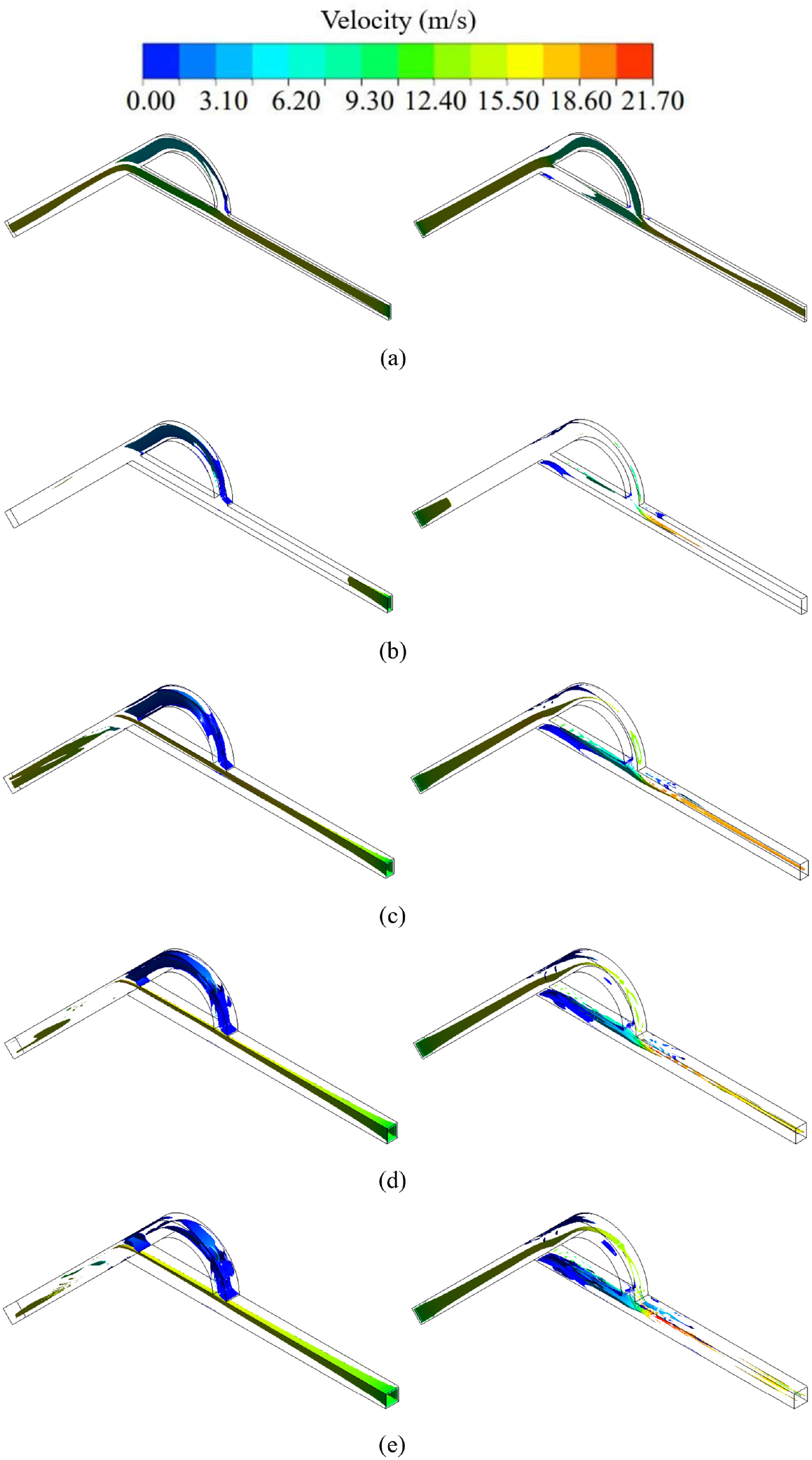
The forward and reverse fluid velocity contours for different flow channel width-to-narrow ratio scenarios are shown in Figure 10, where the incoming flow velocity is 10 m/s.

Velocity contours for different width-to-narrow ratio scenarios (m/s; left: forward flow; right: reverse flow): (a) α = 0.2, (b) α = 0.4, (c) α = 0.6, (d) α = 0.8, and (e) α = 1.0.
When the fluid flows in the forward direction, the majority of it enters the straight channel, with only a small portion entering the arc channel. In the five α cases, the maximum velocity of the straight channel in the forward flow is approximately 10.85, 17.05, 17.05, 17.05, and 17.05 m/s, respectively. In contrast, the maximum velocity of the arc channel is approximately 6.20, 3.10, 3.10, 1.55, and 1.55 m/s, respectively. When flowing in the reverse direction, the arc channel is the primary flow channel; most of the fluid flows into the arc channel, and the maximum velocity of the arc channel is greater than or equal to the maximum velocity of the straight channel. Clearly, the maximum velocity of the primary channel significantly surpasses the maximum velocity of the secondary channel when flowing in the forward and reverse direction, that is, the flow rate in the primary channel is much greater than that in the secondary channel, aligning with the aforementioned flow-through capacity analysis.
Owing to the presence of the middle diversion section, the fluid in the primary and secondary channels influence each other, and the fluid flows complexly and forms jets. For forward flow, the jet is formed at the entrance of the arc channel by the fluid separation in the diversion section, and both the jet intensity and the jet area decrease with the increase of α. For instance, at α = 0.2, the maximum jet velocity is approximately 10.85 m/s. The jet is distributed throughout the arc channel. In contrast, at α = 1.0, the maximum jet velocity is approximately 4.65 m/s, and the jet is only at the arc channel’s entrance.
Furthermore, due to the sudden shift in fluid flow from straight to inclined channels and the fact that the main flow is located in the straight channel for forward flow, there is a sudden increase in velocity at the outlet of the diversion section, creating a jet in this area. As seen in forward flow, the maximum jet velocity does not change significantly as α increases. However, the jet area narrows from the entire inclined channel to the outlet of the diversion section. It indicates that the jet intensity in this region is not sensitive to the α response and that the jet area decreases with increasing α.
For reverse flow, the mainstream in the arc channel and the tributary in the straight channel combine at the outlet of the diversion section forming a jet, and the jet intensity increases with the increase of the α, and there is no significant change in the jet area. As seen, the maximum jet velocity increases from 18.60 to 21.70 m/s with the increase in the α of the flow channel and is distributed throughout the outlet of the diversion section.
It was also observed that the fluid flow in the straight channel shows stratification as the α increases. The reverse flow at α = 1.0 shows that the high-velocity fluid is stratified with the low-velocity fluid, with the high-velocity fluid close to the inner wall and the low-velocity fluid close to the outer wall. However, the high-velocity fluid at small α is distributed throughout the straight channel diversion section. With the increase of the α, the high-velocity fluid area from the straight channel of the diversion section inlet begins to shrink, high-velocity fluid and low-velocity fluid stratification became more and more apparent, and finally showing the characteristics of high-velocity fluid close to the inner wall, low-velocity fluid close to the outer wall.
Vorticity characteristics
Vorticity is the spin of the fluid velocity vector and is an important physical quantity that describes vortex motion. The vorticity 32 is calculated as

Where
Figure 11 shows the vorticity contours for different width-to-narrow ratios at an incoming velocity of 10 m/s, where the vorticity intensity is 60,267.4 s−1. For forward flow, the vorticity is widely distributed throughout the channel under low α. The vorticity at high α is mainly concentrated in the arc channel. The vorticity distribution decreases from the inlet to the outlet of the straight channel. It is rarely distributed in the exit section of inclined channel. When the fluid flows in the reverse direction, the vorticity also exists with much distribution throughout the channel under low α. As α increases, the vorticity distribution changes, with the vorticity volume in the arc channel and the exit section of the straight channel decreasing and finally showing little vorticity volume distribution in these two areas.
Vorticity contours for different width-to-narrow ratio scenarios (left: forward flow; right: reverse flow): (a) α = 0.2, (b) α = 0.4, (c) α = 0.6, (d) α = 0.8, and (e) α = 1.0.
λ2 criterion
The λ2 criterion 33 is a widely used vortex identification method. Here, it is used to capture the vortex structure inside the Tesla valve to compare and analyze the vortex generated area and amount for different width-to-narrow ratios. Moreover, the λ2 criterion is the decomposition of the velocity gradient tensor ∇V, which can be decomposed to a symmetric tensor A (i.e. the deformation of a point in flow field) and an anti-symmetric tensor B (i.e. the rotation of a point in flow field). The equations 34 are

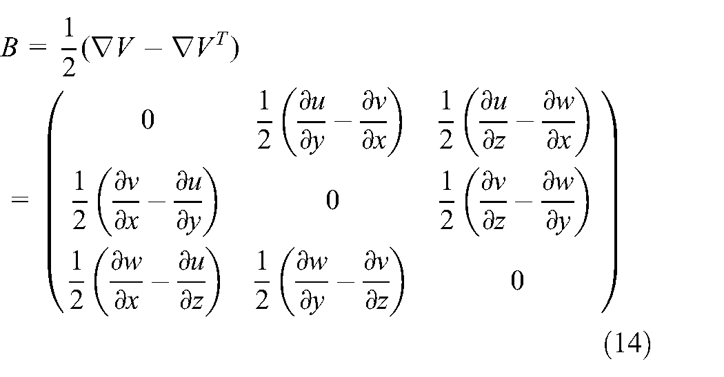
When two negative eigenvalues exist in the symmetric tensor
According to the λ2 criterion, vortex identification is applied to flows with different width-to-narrow ratios at an incoming velocity of 10 m/s. Setting

Vortex distribution for different width-to-narrow ratio scenarios (left: forward flow; right: reverse flow): (a) α = 0.2, (b) α = 0.4, (c) α = 0.6, (d) α = 0.8, and (e) α = 1.0.
For forward flow, the vortex exists mainly in the inlet, diversion, and outlet sections (the inclined channel is the outlet section for forward flow). As α gets changed, the vortex distribution changes. Specifically, when α = 0.2, the vortex in the inlet is tiny; the vortex in the diversion section also exists mainly in the inlet and outlet parts of the diversion section and close to the inner wall of the arc channel; the vortex in the inclined channel is distributed in the inlet part. When α increases, the vortex in the valve increases significantly, and the increase of vortex in the inclined channel is the most obvious: the vortex distribution area increases from the inlet of the inclined channel to the whole inclined channel. Like the forward flow, the vortex in the reverse flow is also mainly distributed in the inlet, diversion section, and outlet section (the straight channel is the outlet section for reverse flow), and the vortex also increases with the increase of α. In addition, the increase in the vortex distribution area and amount is most apparent when α increases from 0.2 to 0.4, regardless of forward and reverse flow. When α increases from 0.4 to 0.6, the vortex distribution area and amount increase, but the increase is slight. Furthermore, when α is 0.6, 0.8, and 1.0, the differences in vortex distribution area and amount are smaller. It indicates that the vortex is more sensitive to changes in α in the small α range.
Conclusion
In this paper, the numerical calculations of forward and reverse laminar flows of Tesla valves were carried out under five different width-to-narrow ratios, which reveal the internal flow characteristics of Tesla valves under varying flow conditions, offering a valuable reference for engineering applications in fluid control. The results found:
(1) As α increases, the flow rate passing the straight channel in forward flow correspondingly increases. Similarly, in reverse flow, an increase in α leads to a bigger flow rate through the arc channel.
(2) When α is small, the flow rate passing the straight channel exhibits a high sensitivity to changes in α. Conversely, when α is large, the sensitivity of the flow rate to α diminishes.
(3) The arc channel is not necessarily the primary channel for overflow in reverse flow.
(4) The pressure in the centerline does not show a monotonic downward trend from the inlet to the outlet.
(5) The pressure curve of the diversion section shows an “∞” shape during forward flow, while the pressure in the arc channel varies in the opposite direction to that in the straight channel. During reverse flow, the pressure curve of the diversion section shows a “flat type” shape, with the pressure in the arc channel consistently higher than that in the straight channel.
(6) The unidirectional conductivity of Tesla valves enhances with increasing width-to-narrow ratio.
(7) Regardless of the forward and reverse flow, the vortex predominantly form within the diversion section, and the vortex at the small α is distributed only in the inlet of the outlet section.
Footnotes
Handling Editor: Chenhui Liang
Declaration of conflicting interests
The author(s) declared no potential conflicts of interest with respect to the research, authorship, and/or publication of this article.
Funding
The author(s) disclosed receipt of the following financial support for the research, authorship, and/or publication of this article: The research was financially supported by Science and Technology Project of Quzhou (Grant No.2023K256) and University-Enterprise Cooperation Program for Visiting Engineers in Higher Education Institutions in Zhejiang Province (No.FG2020215).
Data availability
The data that support the findings of this study are available from the corresponding author upon reasonable request.