
Abstract
Numerous sites for watermills exist in the world with shallow heads and are possible for power generation either mechanical or electrical. The prime mover required for the energy generation from such sites is in the developing phase with efficient, minimum components, and low cost as a modular unit. The Oryon Watermill (OWM) is one of them developed by Deepwater Energy applicable to water current directly. The working of OWM is used differently on the head drop of the canal with fixed and rotating blades using the NACA 6516 series of airfoil shapes as the novelty of this research. The research covers the CFD simulations with ANSYS Fluent 19.0 of two runners, fabrication, and conduction of tests on-site with a head drop of 1.2 m. The major variable was the water flow rate for both runners with the design discharge of 0.09 m3/s. The analysis of results showed the runner with rotating lamellas performed with 9% and 40% higher efficiency from the simulation and experiment respectively compared to the fixed type. The efficiency achieved from the research is at a low range indicating the availability of large space for future study on performance improvement.
Introduction
Globally, the majority of small hydro potential with medium to high heads has already been produced. However, the underutilized ultra-low-head water resources represent a remaining significant possibility.1,2 The ultra-low-head represents the hydraulic head range of 0.5–3 m in general.3,4 In the case of Nepal also there are several such sites favorable for using watermills, approximately 20% of 25,000 of such identified sites have the potential for generating low head power. 5 The Oryon Watermill (OWM) is one of the technologies that can be used for power production in shallow rivers and canals at remote locations. The design is highly adaptable to any site required as the components that make up the turbine system are modular. This essentially means that the design can be fit to any requirement. The patent to the original OWM is owned by Deep Water Energy, Netherlands. It includes the design as well as the method of generating electrical energy using such a device. 6
Traditional forms of hydropower are more likely to be dangerous to aquatic life as such adjustments have to be made to incorporate the passage for aquatic life elsewhere. OWM however, is fish-friendly by design and is not harmful to aquatic life. Therefore, it can be installed without making alterations to the surroundings around the river. 6 Figure 1 shows the working of OWM that develops power at low speed. In conventional practice, a watermill is utilized to extract the energy from the flowing water and convert it into mechanical energy. But further development in the turbine led to the change of this flat blade to curve or airfoil such that it increases the lift causing it to increase in the torque because of the pressure difference created on the opposite side of the airfoil shape.7,8

Working of Oryon Watermill. 9
In general, water turbines are known to have stationary blades whereas the wheel to which the blades are attached rotates by using the energy of moving water. 10 Turbines can be designed to operate with low tidal currents as well. This particular turbine is known as the Achard turbine, and it is a type of water current turbine that is inspired by Darrieus water turbines that are influenced very little by water current directions. Fluent 6.3 has been used to model this open-blade type turbine. 11 The density of water is 900 times more than air thus the size of water turbines working underwater are much smaller than the similar type of wind turbines. The blades of this turbine are supported by radial arms placed mid-way through the axis of the turbine. The height of the rotor is 1 and the arms are 0.5 m long. The blades are designed using the NACA 4518 and NACA 0018 profiles. Two rows of blades are provided in the three blades of the turbine and results are compared with that of the single-row tidal turbine of the same type. Different models are created in which the spacing between the rows of the blades varies concerning the diameter of the blades. The net torque acting on the turbine is reduced which supports the turbine to remain aligned with the tide. The casing of the turbine is 50 m × 50 m × 400 m. 12
A reaction turbine spins at a higher speed without any change in the water head when the rotor of the diameter is small. Higher speed is required for reaction turbines to perform better. The performance of the turbine is done concerning the head, diameter of the rotor, and speed. The power production potential of a site located in Victoria; Australia has been explored by the paper. 13 A vertical turbine water turbine has a cycloidal blade that can be controlled concerning the conditions of the flow. That provision enabled the turbine to extract high power with low water current. 14 CFD analysis has been used as the preferred method to analyze the effects of blade chord length, blade shape, and number of blades on the performance of the turbine. 15 The thickness and camber of the blades are determined to conclude NACA0012 shape is optimum. The results of the tests revealed that the performance of the turbine is better than the ones having fixed pitch blades by 70%. If the blade of the cycloidal turbine is also modified by an individual blade control method, the performance increases by almost another 25%. 14
The turbine researched in another paper works with tidal currents in the southwestern sea, of Korea. NACA 63421 blade shape is incorporated in the turbine, and it is analyzed with the CFD method. 16 The model was drawn for only one of the blades and the periodic equation was used for the calculation of other blades. The turbulence model employed to set up the simulation was the SST k-ω model. The results showed that the dual-rotor setup performed better in comparison to the single-rotor setup.
Similarly, Ansys CFX is used for the computational analysis of a low-head turbine and for that three models of rotors (straight, twisted, and curved) are prepared. 17 During the experiment, the technique of counterweight mass and frictional belt to stop the rotating shaft. It showed that the curved blade profile in a turbine is 87.03% which is greater than the other two models. The testing of the turbine was done in an irrigation channel with 64.36% efficiency. The flow rate of water was around 6 L/s. Another research showed for a low-head axial flow turbine, a tangible connection is established between the two design factors, namely blade height and blade count, and the performance metrics. 18
From the several literatures, there is a need for proper analysis of the runner known as a water wheel with rotating lamellas instead of stationary blades. The analysis by experimental approach is found to be explored very little with regards to turbines. 19 The research gap is based on comparing runners with stationary and rotating blades. The research aimed at the analysis of the performance of the modified OWM through numerical and experimental approaches for two different prototypes, one with fixed and the next with rotating lamellas using the NACA 6516 series of airfoil shape. The shaft axis of the turbine is chosen as vertical being more suitable for the use of low-scale power in rural areas, even though their hydrodynamic efficiency may be lower.20,21 The fluid interaction and frictional losses during the simulation are taken as limitations whereas the experiment has been conducted on-site due to lack of suitable experimental setup.
Research methodology
A simple methodological framework has been developed for this research study to address the identified research gap. The major tasks covered during the study are analytical design, simulation, fabrication, installation, and testing of the turbine. The two runners having fixed lamellas and rotating lamellas for both cases of simulation and experiment have been used. Experimental works later verified the study conducted by simulation of two different runners. Each runner was provided a unique name Runner-A for the runner with fixed blades and Runner-B for the next runner having rotating lamellas. Design parameters for the turbines were taken according to convenience as well as design constraints, primarily head as 1.2 m and flow as 0.0901 m3/s. Other different components are also designed starting from the main shaft, followed by bearing, draft tube, penstock, casing, etc. using the fundamental theories of machine design. 22 The design summary is presented in Table 1 for both of the runners as specifications.
Specification of the runners.
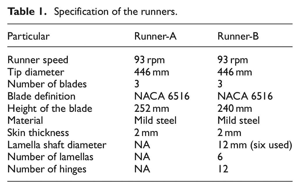
Both the runners are similar in many aspects as presented in Table 1. Based on the dimension from the analytical method, the 3D CAD model of Runners A and B was developed as presented in Figure 2. Runner-B is a modified design of Runner-A where each fixed blade of Runner-A was cut into two separate blades. Each of them was allowed to rotate along the axis of the rotating lamella on individual hinges as shown in Figure 2. The runner can be replaced during the test on the same outer casing and set up as shown in Figure 3 having Runner-A.
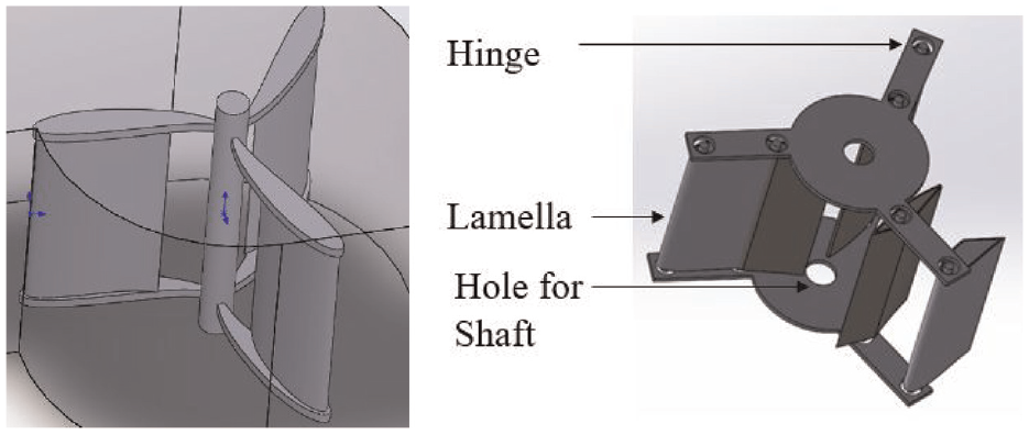
CAD model of Runner-A and Runner-B.
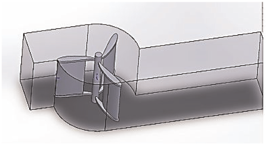
An assembly CAD model of the turbine set up with Runner-A.
Simulation and results
During the CFD analysis of the two models (A and B), the objective was to find the efficiency of the runner for comparison. After the development of the 3D model in Solid Works, it was saved as a step file which was later imported into the Fluent Solver, ANSYS 2019. The mesh used for the analysis is tetrahedral mesh as presented in Figure 4 for the complete system. The boundary conditions were set as listed in Table 2 for analysis on which the maximum iteration to reach convergence was 1000, with residuals within 1 × 10⁻³.

Tetrahedral mesh generation of the complete system.
Boundary conditions for simulation.

In the case of Runner-A, all the blades are fixed, at any instant of time or angle of rotation, there is the occurrence of some back pressure because of the other blades of the runner inside the casing. But, in the case of Runner-B, the feature of the lamella to open and close allows the water flow reducing the effect of back pressure. It causes an increase in the resulting pressure difference. Due to this reason, the resulting pressure difference is low in Runner-A as compared to Runner-B. This eventually increases the power output for Runner-B. Figure 5 shows different zones indicating each side of the blades as A–F with the existence of pressure on each location. The technique applied was that among the three blades, some were omitted during a particular angular position that provided little obstruction to the flowing water. For the simulation, five different angular positions (0°, 15°, 30°, 60°, and 90°) of the blade were chosen for the inlet flow direction. In Figure 5, a blade is in 0° between the zone A and B which is parallel to the inlet flow direction.

Pressure contour of Runner-A for 0° position showing six zones (A–F).
The pressure contour at the 60° and 90° positions for Runner-A is shown in Figure 6 whereas the pressure contour at the 60° and 90° positions for Runner-B is presented in Figure 7. The pressure difference between the pressure and suction sides is noted from the simulation of each angular position. The resulting net pressure difference is the sum of all pressure on each side of the blades given by equation (1) indicating all of the zones, A–F. The plot of the net pressure difference for different positions of blades for both runners is presented in Figure 8.


Pressure contour of Runner-A at 60° and 90° position.

Pressure contour of Runner-B at 60° and 90° position.

Net pressure difference on different blade positions.
From Figure 8, it is clear that the net pressure difference is higher in all cases except 90° among the tests on Runner-B. It is due to the rotating lamina on the arm of the turbine. Further, the power output is calculated by multiplying the net pressure difference with the estimated discharge of the site conditions to get the expected power output (Po) given by equation (2).

The input power is calculated using equation (3) where H is the head acting on the turbine taken as 1.2 m.

After this, the final efficiency is calculated using equation (4) for all of the angular positions23,24

Being the same input power for all of the conditions, the maximum output power is dependent on the amount of net pressure difference that exists. So, the higher the amount of net pressure difference higher the output power resulting in higher efficiency. In a comparison of different positions for both runners, maximum efficiency was obtained in different positions such that Runner-B was found more efficient. The results obtained from the simulation are summarized in Table 3.
Results from the simulation.

Comparing runners with rotating and fixed lamella at specific angles, the simulation showed a favorable overall increase in pressure difference across all blades. Specifically, the design of Runner-B improves water flow against the incoming current by opening between regions F and A, unlike Runner-A. The Runner-A obstructs water flow in this scenario, hindering desired rotation. Efficiency-wise, the Runner-A showed 41.92% and the 90° position whereas the Runner-B attained 46.11% at the 60° position. These values assume the absence of flaps opening against water flow. Overall system efficiency would likely decrease from these results. However, assuming minimal losses apart from the runner, the efficiencies should remain within acceptable ranges like those mentioned. Since the same solid domain (runner) exhibited different properties at different positions as the lamellas opened and closed moving against and toward the direction of the water current, the body had to be assumed different angular positions during rotation. The total lift generated by the airfoil shape blades depends on how much opposite force would be developed due to one-half of the rotor moving in the opposite direction.25,26
Experiment and results
The experimental approach was necessary to validate the concept of power production as well as the results obtained from the numerical simulation of ANSYS. After the analysis of the performance from the simulation, the detailed drawing for fabrication was covered including all of the accessories related to the system. The fabrication was completed at the local workshop with minor corrections using mild steel for all components except the top cover of the casing, which was of acrylic sheet for observation of flow inside the casing. Further, in the absence of an experimental setup in the laboratory, installation was made at the selected site having a head of 1.2 m and enough flow rate available at the drop of Bagmati River, Kupandole, Lalitpur, Nepal.
Figure 9 shows the complete installation of the system from the turbine inlet to the draft tube at the outflow and ready for testing at the site. The work starts with the entering of flow from the turbine inlet that strikes the runner and gets rotated with power, further diverting to the river through the draft tube. The power achieved was measured and documented. Several parameters were necessary to measure using different instruments that are presented in Table 4.

Installation of the complete system at the site.
Measurement of different parameters.

The experiment was performed with varying loads on the pulley through rope used on the top of the vertical shaft of the turbine as a brake dynamometer measured by spring balance. As a result, the optical-type tachometer measured the speed variation. By applying brake force from the dynamometer, the rotation of the shaft gets slow as the load increases23,27 and they were observed for recording. The overall experimental process was repeated for both runners for different flow rates. The shaft power is calculated23,28 using equation (5) and the overall efficiency is calculated from equation (6) on which equations (5) and (3) are used.


Based on the recording of the observation of the experiment conducted, different plots have been generated for comparison of results on both runners. The efficiency for different flow conditions is plotted for Runner-A and Runner-B separately. Figure 10 shows the variation of efficiency with the speed of the Runner-A from 0.062 to 0.066 m3/s of flow rate. The pattern of efficiency for all of the flows is found similar. The maximum efficiency of 17% was achieved on 76.5 RPM for flow 0.063 m3/s with a power of 137.53 W. Similarly, Figure 11 shows the variation of efficiency with the speed of the Runner-B from 0.08 to 0.089 m3/s of flow rate. The pattern of efficiency for all of the flows for Runner-B is also found similar. The maximum efficiency of 28.67% was achieved on 64.4 RPM for flow 0.083 m3/s with a shaft power of 281.172 W.
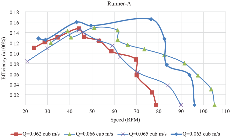
Variation of efficiency on different speeds for Runner-A.

Variation of efficiency on different speeds for Runner-B.
From the comparison of experimental data, Runner-B was found more efficient with 11.67% higher than Runner-A. It concludes the concept of the rotating phenomenon of lamellas on the arm of the runner is found more effective than the fixed one practically also. Keeping all the other parameters on site the same, the consumption of flow rate is found distinct for two runners. As presented in Figure 12, the consumption of flow rate by Runner-A is in the lower range and has lower efficiency compared to Runner-B.
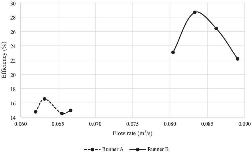
Variation of efficiency on different flow rates.
Conclusion
A turbine, an Oryan water mill used in river current was proposed to research for performance in the case of head drop installation with modification in original design at low-cost option. A comparison was made between the performance of two different runners – one with fixed blades (Runner-A) and the next with rotating lamellas (Runner-B). For both runners, analysis with CFD simulation and experimental activities was conducted. Both of the analyses concluded that higher efficiency is achieved from runners with rotating lamellas.
The simulation performed on ANSYS 2019, resulted in 41.92% maximum efficiency for Runner-A and 46.11% for Runner-B. Similarly, the experiment conducted on site after the fabrication showed a maximum efficiency of 17% was achieved on 76.5 RPM for flow 0.063 m3/s with a power of 137.53 W for Runner-A and 28.67% was achieved on 64.4 RPM for flow 0.083 m3/s with a shaft power of 281.172 W for Runner-B. In both types of analysis, the runner with rotating lamellas is found more efficient though there is a difference in the resulting value due to different assumptions made during the simulation. This is the research concluded with validation of the concept of working with the modified form of the Oryan watermill on the head drop of the canal. The efficiency achieved from the research is at a low range providing a large space for future study on the optimization of blade profiles, casing, quantity of lamellas, and minimizing the frictional effect on rotation for higher performance.
Footnotes
Acknowledgements
The authors recognize the financial aid provided by the Institute for Social and Environmental Transition, Nepal: ISET-N for this research. The local fabrication workshop, Vortex Engineering Concern Pvt. Ltd. is thankful for all types of field support on fabrication and installation. Also, the assistance received from all of the members of the Department of Automobile and Mechanical Engineering, Institute of Engineering, Thapathali Campus for the completion of this research, is acknowledged.
Handling Editor: Jose Ramon Serrano
Declaration of conflicting interests
The author(s) declared no potential conflicts of interest with respect to the research, authorship, and/or publication of this article.
Funding
The author(s) disclosed receipt of the following financial support for the research, authorship, and/or publication of this article: This study was supported by a grant from the Institute for Social and Environmental Transition, Nepal: ISET-N (Grant No. Engineering-03-2018).
Data availability
Data can be shared on request.