
Abstract
This paper presents the flexural property of damaged steel-concrete composite girders strengthened with CFRP sheet or prestressed CFRP sheet. Test and numerical analysis were used in the girders. The test findings indicated that the damage level had a substantial impact on the stiffness, yield strength, and ultimate load. And because of the CFRP sheet or prestressed CFRP sheet, the ultimate bearing capability could increase. The findings of the numerical analysis indicated that the increase of concrete strength would improve the stiffness and bearing capability. Increasing the web’s thickness and the steel beam’s flange by 1 mm would result in an approximate increase in the carrying capacity of roughly 4% and 3.8%, respectively. The damage level had a substantial impact on the stiffness and ultimate bearing capability. The bearing capacity would increase by about 2.8% with each additional 0.05 mm of thickness in the CFRP sheet. When the prestressed degree increased by per 5%, the bearing capacity would experience a 1.4% rise and the CFRP sheet’s stress would increase.
Introduction
Shear connectors are used to link the concrete slab with the steel beam in the steel-concrete composite girder. Within this girder, the concrete slab primarily experiences compressive forces, while tensile forces are applied to the steel beam. The composite girder optimally utilizes the compressive capabilities of concrete and the tensile properties of steel, making it a commonly employed material in construction and bridge structures. However, after long-time use, the steel beam would be corroded1–3 and the high traffic volume would increase the burden of the girders and accelerate the damage of girders. The aforementioned factors would result in a decrease in both the bearing capacity and durability of the composite girder. Many study papers suggest that it is advisable to explore the option of repairing and retrofitting a structure or bridge before deciding to replace it. Strengthening existing composite girders is cheaper and easier than replacing the girders and it also doesn’t influence the use of the girders. Prior studies have demonstrated that carbon fiber-reinforced polymers (CFRP) have exceptional mechanical and physical qualities, rendering them highly suitable for repairing and reinforcing concrete or steel-concrete composite girder.4–7 Over the course of the previous decade, multiple studies have been undertaken to investigate the repair and retrofitting of steel beam and composite girders through the utilization of epoxy-bonded fiber-reinforced polymers (FRP) materials.
According to Chen et al., 8 a test of bending fatigue was performed on steel beams of rectangular hollow section (RHS) that underwent repair utilizing prestressed CFRP plates. The results of the study suggest that the performance of fatigue can be enhanced by employing a material with a greater modulus or by raising the level of prestressing. The stiffness of beams that underwent repair using prestressed carbon fiber reinforced polymer (CFRP) plates showed a minor reduction, but beams repaired using non-prestressed carbon fiber reinforced polymer (CFRP) plates demonstrated a substantial reduction in rigidity under fatigue loading conditions. Keykha 9 investigated the effect of CFRP strengthening on the behavior of defective vertical curved steel beams with a square hollow section. The results indicated that the use of CFRP sheets for strengthening defective curved beams could recover the strength lost due to a defect significantly. The width of CFRP sheets, specifically 100, 300, and 400 mm, had an impact on the ultimate load. In all specimens, the maximum von Mises stress was at their midspan. Al-Ridha et al. 10 examined the impact of reinforcing four steel beams with carbon fiber on deflection of load, load-strain, and ultimate load responses, while varying the span lengths. The study revealed that reducing the effective length of beams, both with and without carbon fiber reinforcement, resulted in increased stiffness as observed by load deflection and load-strain response. This impact was particularly pronounced in beams reinforced with carbon fiber. In contrast, the findings from the ultimate load tests conducted on the beam suggest a positive correlation between the percentage rise in ultimate load and the reduction in length of span for the beam reinforced with carbon fiber. It can be deduced that a decrease in the effective length leads to an increase in the ultimate load, and magnitude of this increase is enhanced by the use of carbon fiber. Zhang et al. 11 investigated the flexural behavior of corroded steel beams strengthened by carbon fiber reinforced polymer (CFRP) plate. The results showed that failure modes of corroded beams were the fracture of the CFRP plate after the shear failure of interface on the mid-span and fracture location of CFRP plate was mostly at the loading point. The rough surface of the corroded steel can enhance the efficiency of stress transfer at the interface, thereby improving the effective bond length of the interface. The shear stress was mainly concentrated on the CFRP plate end, and peak value appeared at the loading point. Compared the reference beam, the ultimate flexural capacity of the corroded beam strengthened by CFRP plate with 15% prestress level increased at a ratio of 21%, and utilization ratio of the CFRP plates was up to 71.59%. In a study conducted by Teng et al. 12 examining the stress distribution on the bending interface of a main steel beam was investigated under different environmental temperatures. The results show that the bending capacity of long-span steel main beams is improved by CFRP. The experimental results also indicate that insulation and protection of the rubber layer are important factors in the effectiveness of CFRP. Hosseini et al. 13 present a methodology for determining the least amount of prestressing force needed to completely prevent cracks from propagating in steel I-beams. Models utilizing linear elastic fracture mechanics (LEFM) were created and validated through experimental data. Experimental evidence demonstrated that the application of prestressed CFRP composites can induce a device for closing cracks, whereby the crack’s surfaces remain in a closed position even when subjected to significant external forces. In addition, it has been demonstrated that the inclusion of the CFRP’s stiffness in the formulation of the analysis can result in a reduction in the required prestressing to impede the advancement of fatigue cracks. Deng et al. 14 tested eight prestressed CFRP tendon enhanced steel reinforced concrete members under monotonic eccentric tensile loading. The results demonstrated an improvement in the eccentric tensile capacity of PSRC members upon increasing both the steel and reinforcement ratios, or by reducing the prestress eccentricity, and enhancement in the level of prestressing increased can decrease the crack propagation and lateral deflection. The technique proposed by Hu et al. 15 involves the utilization of prestressed CFRP laminates for the purpose of enhancing the bending resistance of steel purlins. A comprehensive study was undertaken to examine the flexural characteristics of reinforced steel purlins through a combination of experimental and theoretical investigations. The findings indicated that the utilization of prestressed CFRPs successfully delayed the occurrence of flexural damage resulting from the localized bends or yielding of the top plate. The results of the tests indicated a notable enhancement in both flexural strength and stiffness, with improvements ranging from 14% to 18% and 28% to 31% respectively. Knoll et al. 16 conducted a study to assess the efficacy of outside bonded small-patch ultrahigh-modulus (UHM) CFRP plates with a modulus of 460 GPa. Results showed that fatigue life was increased by up to 2.0 and 2.34 times for single- and double-sided UHM CFRP repairs. As bond length increased from 25 to 100 mm, fatigue life increased from 1.36 to 2.0. UHM CFRP more effectively reduced stress concentration at the crack tip, by 60% compared with 37% for NM CFRP, indicating that it had the potential for superior fatigue life gains, relative to NM CFRP if the necessary bond length to prevent or delay debonding was provided. Deng et al. 17 present a well-rounded experimental study on the flexural performance of Reinforced Concrete (RC) box girders strengthened with prestressed carbon fiber reinforced polymer (CFRP) plates. The test results suggested that the crack load increased by 86% and 134%, when the specimens were enhanced with the combinations of 30% prestress level for the same CFRP cross-section, and 40% prestress level with a thicker CFRP plate, respectively. The flexural capacity also increased by 42% and 72%, and flexural stiffness increased by 3% and 63%, respectively.
Research on enhancing the properties of steel or steel-concrete composite materials mostly focused on improving characteristics such as strength, length, bearing capacity, and stiffness. However, there have been few research undertaken on the steel-concrete composite girder, particularly regarding the reinforcement of the composite girder. In this study, the mechanical behavior of damaged steel-concrete composite girders strengthened with CFRP sheet is studied by test and finite element simulation, and the concrete strength, prestress level, strength of steel beam and other parameters are analyzed.
Experimental program
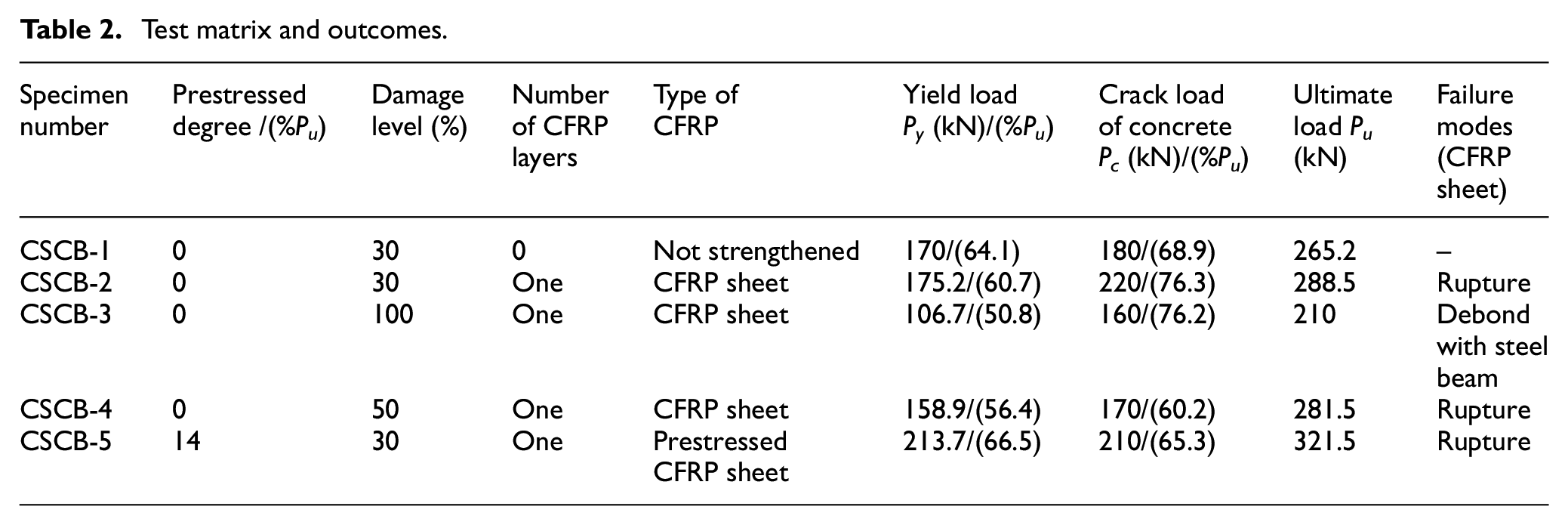
The experiment utilized typical Chinese Standard steel I20A as the material for the steel beam. The flange had a width of 100 mm, with the flange and web having thicknesses of 11.4 and 7 mm respectively. The section had an area of 3550 mm2. The steel beam was attached to a concrete slab with a wide of 900 mm by 80 mm thick, as shown in Figure 1(a). The steel sections were divided into beams of 3.0 m in length. At the midpoint of these beams, three different levels of damage were inflicted on the tension flange, resulting in losses of 30%, 50%, and 100%, as depicted in Figure 1(b). The steel reinforcement cage within the concrete slab consisted of two layers of 12 mm HRB335 steel bars and stirrups, accompanied by 6.5 mm plain bars spaced at intervals of 150 mm, as depicted in Figure 1(c). The steel girder and slab of concrete were connected by means of shear connectors. The CFRP sheets had a length of 2400 mm, a width of 80 mm, and a thickness of 0.167 mm per sheet. The mechanical properties of materials was shown in Table 1. There were two types of sheets: prestressed carbon fiber reinforced polymer (CFRP) sheet and non-prestressed CFRP sheet with an adhesive coating. The prestress was applied to the CFRP sheets by using self-made stretching bed. Implementation method: fixed CFRP sheets by two steel slabs with four bolts at the end of stretching bed and four screws which could move up and down applied prestress to the CFRP sheets by raising the supports horizontally, as shown in Figure 2. Finally, pasted the U-shape hoops at the end of CFRP sheets to make sure the CFRP sheets could be anchored to the composite girders. Four-point bending tests were performed using hydraulic jacks and the test detail parameter was shown in Figure 3. Monotone grading loading was adopted in this test. And the load of each stage was 2 kN. When the specimen was close to failure, slowly and continuously loading was used until the specimen was destroyed. The detailed parameters of the composite girders were given in Table 2.

The preparation of specimens: (a) geometry size and cross-section diagram of the specimen (unit: mm), (b) corroded model, and (c) formwork for concrete slab.
Mechanical properties.


Implementation apparatus for prestressing CFRP sheet.

Loading device of test.
Test matrix and outcomes.
Test results
Failure mode
The failure modes of steel-concrete composite girders reinforced with CFRP sheet or prestressed CFRP sheet can manifest in several ways, such as concrete crushing, CFRP rupture, CFRP debonding, and the steel beam web being crippled.
The lower flange of the steel beams began to yield at around 50%–60% of the ultimate load. The top surface of the concrete slab exhibited a few longitudinal fractures across the web of the beam of the steel when subjected to a load ranging from approximately 65% to 75% of its ultimate capacity, as illustrated in Figure 4(a).
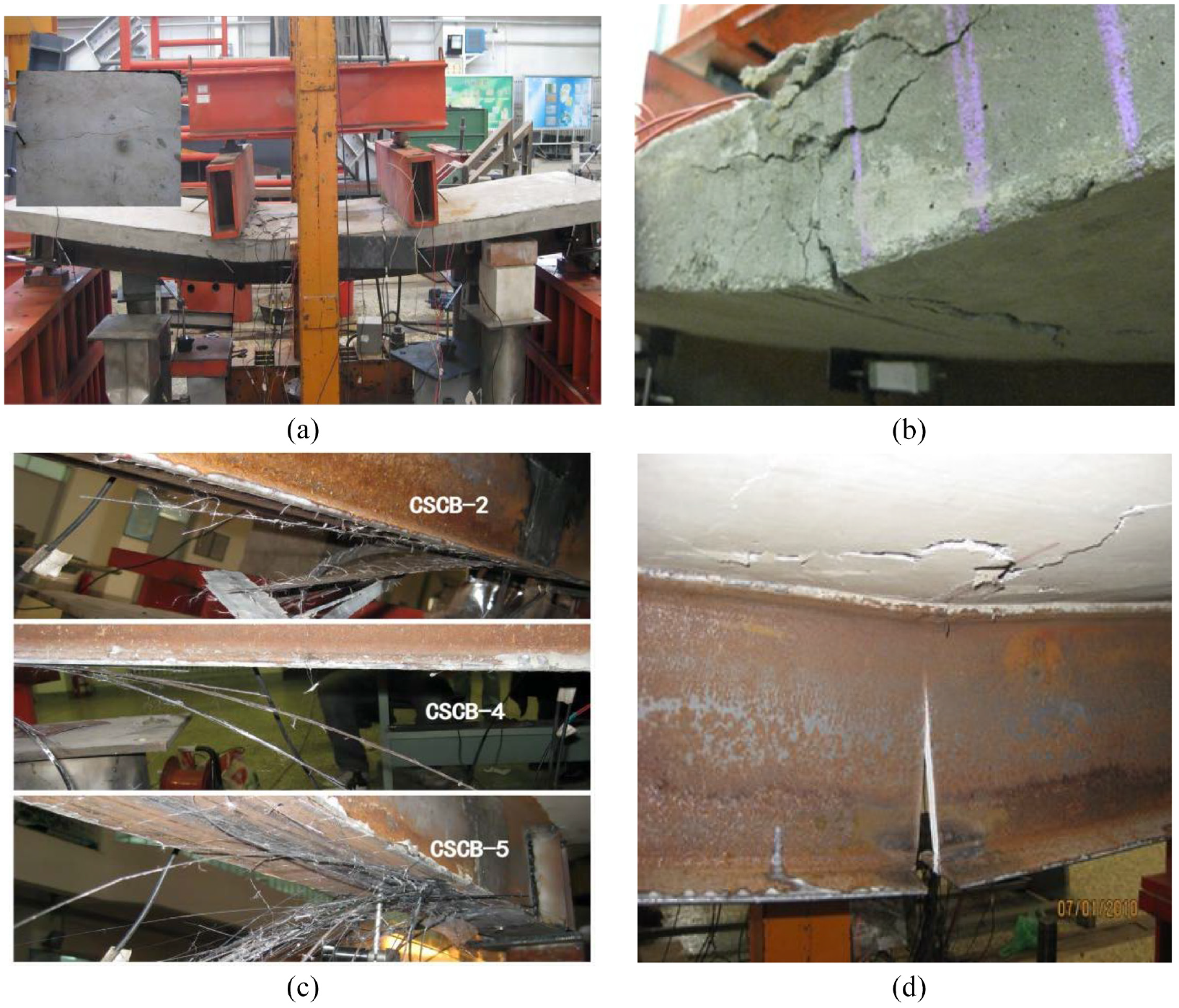
Failure modes of test specimens: (a) longitudinal crack of concrete slab (CSCB-1), (b) concrete being crushed, (c) rupture of CFRP sheets (CSCB-2, 4, 5), and (d) web crippling (CSCB-3).
Figure 4(b) illustrates that the main type of failure seen in this test was the crushing of concrete. The specific manner of failure seen in the composite girders was the tension rupture of CFRP sheets, as depicted in Figure 4(c). The specimens of CSCB-2, CSCB-4, and CSCB-5 experienced sudden breakage of the CFRP sheet, with no evidence of adhesive failure occurring between the carbon fiber reinforced polymer sheet and the flange of steel.
A structural failure occurred in girder CSCB-3, causing the crippling to the beam of steel and debonding between the carbon fiber reinforced polymer sheet and the flange of steel. At almost 50% of the ultimate load, the tensile flange of the steel beam began to yield. As stress levels rose, the carbon fiber reinforced polymer sheet experienced a phenomenon where its color became darker. The debonding developed quickly from the first sign at the cut in the mid-span (when the load was 90% of the ultimate load). The web of the steel beam ruptured at the same time as the CFRP sheet debonded, as shown in Figure 4(d).
Effect of flange damage level
The connection between load and deflection of the composite girders with varying levels of flange damage, which were repaired with one layer of CFRP sheet, was depicted in Figure 5(a). Damage levels of 30%, 50%, and 100% missing the tension flange at the mid span of steel beams were observed in CSCB-2, CSCB-4, and CSCB-3, respectively. CSCB-1 served as the control specimen. The yield load and ultimate load of CSCB-2 were 175.2 and 288.5 kN, which were respectively 10.2% and 3.2% greater than that of CSCB-4, and were 64.2%, 37.4% greater than that of CSCB-3. The ultimate load of CSCB-4 was 281.5 kN, which was 6.1% greater than that of CSCB-1; the ultimate load of CSCB-3 was 210 kN, which was 20.8% smaller than that of CSCB-1. The extent of flange damage has a substantial impact on yield load and the ultimate load. A single layer of CFRP sheet was insufficient to compensate for the girders’ lack of bearing capacity when the flange damage reached 100%. However, it was capable of compensating for the girders’ lack of bearing capacity when the flange damage reached 30% and 50%.

Correlation between composite girder deflection and load: (a) effect of flange damage level and (b) effect of prestressed CFRP sheets.
Effect of prestressed CFRP sheets
Figure 5(b) illustrates the connection between load and deflection of composite girders with 30% flange damage that were repaired using CFRP sheet or prestressed CFRP sheet. CSCB-1 served as the control specimen. CSCB-2 was repaired with one layer of CFRP sheet and CSCB-5 was repaired with one layer of prestressed CFRP sheet. The yield load of CSCB-5 was 213.7 kN, which was 21.9% and 25.7% greater than that of CSCB-2 and CSCB-1, respectively, and the elastic stiffness was 17.3% and 35.33% greater than that of CSCB-2 and CSCB-1, respectively. The ultimate load of CSCB-5 was 321.5 kN, which was 11.4% and 21.2% greater than that of CSCB-2 and CSCB-1, respectively. The test results showed that the yield load, elastic stiffness, and ultimate bearing capacity of strengthened steel-concrete composite girders had been changed as a result of prestressed CFRP sheets.
Numerical analysis
Material properties
Concrete slab
The damage model was applied to the concrete slab, as illustrated in Figure 6, the elastic modulus was 31,500 MPa, Poisson’s ratio was 0.4, and the stress-strain relationship was:

Where

Stress-strain curve of concrete.
Steel beam
The steel beam was assumed to be an elastic-plastic material identical in tension and compression as shown in Figure 7 and the relationship of stress and strain was:

Where:
Steel’s stress-strain relationship.
CFRP sheet
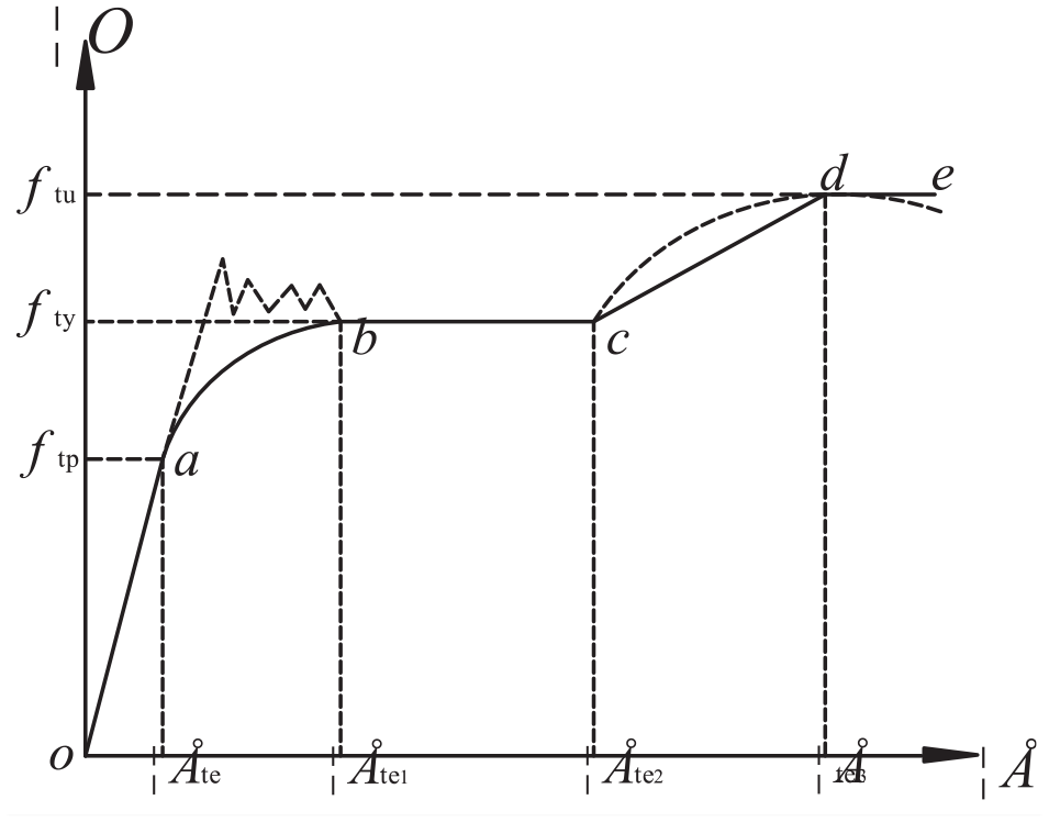
The CFRP sheet was assumed to be an orthotropic material as showed in Figure 8 and the relationship of stress and strain was:

Where:

Relationship between stress and strain in CFRP sheet.
Model development
The software ABAQUS was utilized to conduct the numerical analysis. The model’s geometry and loading arrangements were designed based on the beams that were tested in the experiment. Figure 9 illustrates the creation of a three-dimensional element (C3D8R) for concrete slab and steel beam. Additionally, a three-dimensional truss element with two nodes in linear integral format was employed for reinforcement. Furthermore, an element of the shell type (SR4) was utilized for CFRP sheet.

Model development: (a) concrete slab, (b) reinforcement, (c) steel beam, and (d) CFRP sheet.
Prestressing
The method of dropping temperature was utilized by the ABAQUS program to impart prestress to the carbon fiber reinforced polymer sheet. The correlation between temperature and load was:
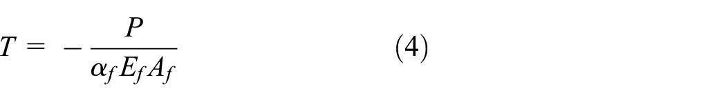
Where:
Stress analysis
Figure 10 showed the load-deflection curve of damaged composite girder strengthened with CFRP sheet. The graph between load and deflection exhibited nonlinearity, which consisted of three distinct periods: elastic phase, elastic-plastic phase, and plastic phase. During the initial period, the deflection of a composite beam exhibits a constant increase in response to the load. During the elastic phase, the reinforced composite girder’s deflection exhibited a gradual increase as the applied load increased. During the elastic-plastic phase, the deflection of the reinforced composite girder exhibited a rapid increase in response to the applied load. During the plastic phase, the deflection of the reinforced composite girder exhibited a rapid increase, whereas the load experienced a slight increase.

Load-deflection curve of composite girder.
Figure 11 depicted the concrete slab, steel beam, and CFRP sheet’s stress. Upon reaching approximately 75% Pu (Pu was the ultimate load), the steel beam’s lower flange experienced yielding. However, the yielded area was limited in light of the presence of the carbon fiber reinforced polymer sheet. When load level is approximately 85% Pu, the beam of steel’s upper flange experienced yielding. The lower flange’s yielding area rose. Upon reaching the ultimate load, the steel beam experienced yielding, resulting in the crushing of the concrete slab within the compression region. The reinforced composite girder experienced failure.

Stress images: (a) 75% Pu, (b) 85% Pu, and (c) 100% Pu.
Figure 12 showed the relationship of stress along concrete slab length, steel beam length, and CFRP sheet length. Owing to the concentration of stress at the loading location, the compressive stress at the loading location consistently exhibited the highest magnitude toward concrete slab length. The compressive stress at point A and B was comparable at both the midpoint of span and the loading location. Upon reaching point C, the compressive stress exhibited its highest magnitude at the loading point, with the stress thereafter reaching its peak at the mid-span. Toward the beam of steel length, the stress of tensile exhibited similarity at points A, B, and C. Point C exhibited a slightly higher tensile stress compared to points A and B. Point A exhibited the lowest compressive stress, while points B and C displayed similar compressive stress levels. The stress concentration at the bottom flange and the loading location in the direction of carbon fiber reinforced polymer sheet length resulted in the highest stress in the mid-span stress at points A and B, followed by the tension at the bearing point. At point C, stress at the loading location exhibited the highest magnitude, with the stress at the mid-span following suit.

Stress curves: (a) stress along concrete slab, (b) stress along steel beam, and (c) stress along CFRP sheet.
Deflection analysis
The deflection image of the reinforced composite girder was depicted in Figure 13. The yielding of the steel beam’s lower flange caused a deflection of approximately 14 mm, while the yielding of the steel beam’s top flange led to a deflection of approximately 20 mm. The ultimate deflection of the reinforced composite girder was 71.2 mm.

Displacement image.
The comparison of numerical analysis and test
The comparison between load and deflection between numerical analysis and test was depicted in Figure 14. Compared the numerical results and test results, agreement was also achieves no matter the composite girder was strengthened with CFRP sheet or strengthened with prestressed CFRP sheet.

The comparison of numerical analysis and test: (a) CSCB2, (b) CSCB3, (c) CSCB4, and (d) CSCB5.
Parameter analysis
Concrete strength
The load-deflection relationship of a reinforced composite girder with varying concrete strength was depicted in Figure 15. In comparison to the reinforced composite girder with a concrete strength of C30, the ultimate load of the reinforced composite girder with concrete strengths of C35, C40, C45, C50, and C55 were found to be 2.5%, 5.4%, 7.2%, 41.7%, 8.6%, and 9.9% higher, respectively. The findings indicated that an increase in concrete strength resulted in an increase in both stiffness and ultimate bearing capacity. However, it was observed that the magnitude of this increase decreased as the concrete strength increased. The greatest compressive stress observed at the loading location of the concrete suggests that the failure mode was the crushing of the concrete at that specific location. The steel beam exhibited comparable tensile and compressive stress, with the stress of tensile at the midpoint of span slightly surpassing that at the loading location. The carbon fiber reinforced polymer (CFRP) sheet saw its highest stress at the loading location, with the stress in the midpoint of span being the second highest. The alteration in the strength of concrete had a little impact on the stress experienced by the beam of steel and carbon fiber reinforced polymer sheet. As the strength of concrete increases, there is a corresponding drop in its compressive stress, albeit with a minimal magnitude.

Effect of concrete strength: (a) load and deflection, (b) stress along concrete slab length, (c) stress along steel beam length, and (d) stress along CFRP sheet’s length.
Web thickness of steel beam
The load-deflection relationship of a reinforced composite girder with varying web thickness of steel beam was depicted in Figure 16. The reinforced composite girder with web thicknesses of 6, 7, 8, 9, 10, 11, and 12 mm exhibited ultimate loads that were 4.6%, 9.1%, 13.5%, 17.7%, 21.9%, 25.9%, and 29.8% higher, respectively, compared to the reinforced composite girder with a web thickness of 5 mm. The results exhibited that augmenting the thickness of the web will lead to an augmentation in both stiffness and ultimate bearing capacity. As the web thickness grew by 1 mm, there was an observed improvement in bearing capacity of around 4%. The compressive stress of concrete exhibited minimal variation as the web thickness increased. The steel beam exhibited a drop in tensile stress as the web thickness increased, whereas the compressive stress of the beam remained rather constant. As the web thickness increased by 1 mm, the stress of tensile in the midpoint of span would decrease by approximately 0.6 N/mm2. The carbon fiber reinforced polymer sheet’s stress dropped as the web thickness increased. As the web thickness increases by 1 mm, the stress of the carbon fiber reinforced polymer sheet at the loading location decreases by approximately 60 N/mm2.

Effect of web thickness of steel beam: (a) load and deflection, (b) stress along concrete slab length, (c) stress along steel beam length, and (d) stress along CFRP sheet’s length.
Flange thickness of steel beam
The load-deflection relationship of a reinforced composite girder with varying flange thickness of steel beam was depicted in Figure 17. The reinforced composite girder with flange thicknesses of 8, 9, 10, 11, 12, 13, and 14 mm exhibited ultimate loads that were 4.1%, 8%, 11.9%, 15.7%, 19.3%, 22.9%, and 26.4% higher, respectively, compared to the reinforced composite girder with a flange thickness of 7 mm. The experiment demonstrated that augmenting the thickness of the flange will result in an increase in both stiffness and ultimate bearing capacity. As the thickness of the flange grew by 1 mm, there was an observed increase in bearing capacity of around 3.8%. There was minimal variation observed in the compressive stress of concrete as the flange thickness increased. The steel beam exhibited an increase in tensile stress as the flange thickness grew, whereas the compressive stress of the beam remained relatively constant. The tensile stress had a positive correlation with the flange thickness, with an increase of around 0.8 N/mm2 every 1 mm. The stress experienced by a CFRP sheet exhibits a positive correlation with the thickness of flange. The stress experienced by the carbon fiber reinforced polymer (CFRP) sheet at the loading point would rise by approximately 40 N/mm2 for every 1 mm increase in thickness of the flange.

Effect of flange thickness of steel beam: (a) load and deflection, (b) stress along concrete slab length, (c) stress along steel beam length, and (d) stress along CFRP sheet’s length.
Damaged level of steel beam
The load-deflection relationship of a reinforced composite girder with varying damage level of steel beam was depicted in Figure 18. The ultimate load of strengthened composite girder with damage level of 10%, 20%, 30%, 40%, 50%, 60%, 70%, 80% were respectively 58%, 51.8%, 45.5%, 39.2%, 32.8%, 26.3%, 19.8%, 13.3%, 6.7% greater than that of the strengthened composite girder with the damage level of 10%. It showed that the increase of damage level would decrease the stiffness and ultimate bearing capacity, especially the influence on the ultimate bearing capacity. As the level of damage increases, the compressive stress of concrete, the beam of steel’s tensile and compressive stress, and the carbon fiber reinforced polymer sheet’s stress exhibit a drop. With a 10% rise in damage level, the compressive stress of concrete exhibits a decrease of around 0.6 N/mm2. Similarly, the beams of steel’s tensile and compressive stress experience a decrease of approximately 16 and 15.9 N/mm2, respectively. Additionally, the stress of CFRP sheets demonstrates a decrease of approximately 30 N/mm2. The study shown that the escalation of damage level significantly impacted the stress levels of concrete, steel beams, and carbon fiber reinforced polymer sheets.

Effect of damage level of steel beam: (a) load and deflection, (b) stress along concrete slab length, (c) stress along steel beam length, and (d) stress along CFRP sheet’s length.
Thickness of CFRP sheet
The load-deflection relationship of a reinforced composite girder with varying thickness of CFRP sheet was depicted in Figure 19. The strength of the reinforced composite girder increased by 2.8%, 5.7%, 8.5%, 11.3%, 14.1%, 16.8%, 19.6%, and 22.3% when the CFRP sheet thickness was 0.15, 0.2, 0.25, 0.3, 0.35, 0.4, 0.45, and 0.5 mm, respectively, compared to the reinforced composite girder with a CFRP sheet thickness of 0.1 mm. The findings indicated that augmenting the thickness of CFRP sheets resulted in enhanced stiffness and ultimate bearing capacity. By increasing the CFRP sheet’s thickness by 0.05 mm, there is an observed increase in bearing capacity of around 2.8%. The alteration in CFRP sheet’s thickness had minimal impact on the compressive stress of concrete and the steel beam’s stress, however, it exerted a distinct impact on the stress experienced by the CFRP sheet. The stress experienced by CFRP materials exhibited a negative correlation with the carbon fiber reinforced polymer sheet’s thickness. As the thickness of the carbon fiber reinforced polymer sheet increases by 0.05 mm, there is an observed decrease in the carbon fiber reinforced polymer sheet’s stress by approximately 20 N/mm2.

Effect of thickness of CFRP sheet: (a) load and deflection, (b) stress along concrete slab length, (c) stress along steel beam length, and (d) stress along CFRP sheet’s length.
Prestressed degree of CFRP sheet
The load-deflection relationship of a reinforced composite girder with varying prestressed degree of CFRP sheet was depicted in Figure 20. The reinforced composite girder with prestressed degrees of 5%, 10%, 15%, 20%, 25%, and 30% exhibited ultimate loads that were 1.1%, 2.3%, 3.8%, 5.2%, 6.6%, and 7.8% higher, respectively, compared to the reinforced composite girder with a prestressed degree of 0. The experiment demonstrated that augmenting the prestressed degree will result in an augmentation of both stiffness and ultimate bearing capacity. When the prestressed degree was increased by 5%, there is an observed increase in bearing capacity of around 1.4%. The variation in prestressed degree had minimal impact on the compressive stress of concrete and beam of steel, while exerting significant influence on the carbon fiber reinforced polymer sheet’s stress. The stress experienced by carbon fiber reinforced polymer exhibited a positive correlation with the degree of prestressing. With a 5% increase in the prestressed degree, the carbon fiber reinforced polymer sheet’s stress would be enhanced by approximately 60 N/mm2.

Effect of prestressed degree of CFRP sheet: (a) load and deflection, (b) stress along concrete slab length, (c) stress along steel beam length, and (d) stress along CFRP sheet’s length.
Conclusion
(1) The test result showed that the steel-concrete composite girder strengthened with CFRP sheet or prestressed CFRP sheet could display several distinct failure modes including: concrete being crushed, CFRP rupture, CFRP debonding, and the web of steel beam being crippled. The damaged level had a significant effect on the stiffness, yield load, and ultimate load. And the CFRP sheet or prestressed CFRP sheet could increase the bearing capacity.
(2) By comparing the numerical results and test results, agreement was also achieves no matter the composite girder were strengthened with CFRP sheet or prestressed CFRP sheet. Nonlinearity was seen in the curve of load-deflection, which consisted of three distinct phases: elastic phase, elastic-plastic phase, and plastic phase.
(3) The findings from the study of numerical indicate that enhancing the strength of concrete leads to improvements in both stiffness and bearing capacity. An increase of 1 mm in the web’s thickness and the steel beam’s flange’s thickness would result in a corresponding increase of approximately 4% and 3.8% in the bearing capacity, respectively. An elevation in the level of damage to a steel beam would result in a reduction in its bearing capacity. As the carbon fiber reinforced polymer sheet’s thickness grew by 0.05 mm, the bearing capacity would increase by approximately 2.8%. An increase in the prestressed degree by 5% would result in a corresponding increase of approximately 1.4% in the bearing capacity and the carbon fiber reinforced polymer sheet’s stress would increase.
Footnotes
Handling Editor: Sharmili Pandian
Declaration of conflicting interests
The author(s) declared no potential conflicts of interest with respect to the research, authorship, and/or publication of this article.
Funding
The author(s) disclosed receipt of the following financial support for the research, authorship, and/or publication of this article: This work was upheld by the Education Department of Liaoning Province (No. LJKQZ20222313) and Liaoning Provincial Department of Natural Science (No. 2022-MS-399).
Data availability
The corresponding author can provide access to the data, models, and code that substantiate the outcomes of this work upon a fair request.