
Abstract
In order to improve the efficiency of unconstant-pressurized chamber rock drills in large-hole and hard-rock conditions, the coupling characteristics of high-pressure accumulator and the impact system were analyzed. The multi-parameter mechanism experiment was designed. Piston displacement, oil return flow, main input-oil, and internal chamber pressure were obtained. Combining the structural characteristics and working principles of rock drills, the experiment-based accumulator volume calculation methods was proposed. According to the phase plane analysis of the accumulator diaphragm and the time series analysis of impact performance parameters, which indicate that the high-pressure accumulator and impact system have typical non-contact nonlinear structures. The dynamic performances also present complex nonlinear characteristics. With the increase of gas pre-charge pressure, the bifurcation points were developed from period-one motions to period-two motions, the coupling degree of flow coupling between the accumulator and the impact piston was gradually enhanced, and the impact performance was gradually improved. With the formation of the period-one motions and the increase of bifurcation strength, the diaphragm became more susceptible to fatigue damage. The optimum choice of high-pressure accumulator gas pre-charge pressure is 80–90 bar, which provides a reference for the application and parameter setting of high-pressure accumulators in unconstant-pressurized chamber rock drills.
Keywords
Introduction
With the evolution of rock drilling method, the working conditions for large-hole and hard-rock have gradually increased, and the requirements for the impact performance of rock drills have also become more demanding.1–3 The phenomenon of impact powerlessness is becoming more apparent, when rock drills are faced with such working conditions. Unconstant-pressurized chamber rock drills were widely used in rock drilling operation due to its advantages of high output power and energy conversion efficiency, which attracts many scholars to focus on its impact characteristics and research.4,5
The impact system of rock drill mainly consists of impact piston, reversing valve and high-pressure accumulator, which is a complex system of machine-liquid-gas coupling. In the existing related research, both domestic and foreign scholars have tried a variety of methods to analyze the accumulator effect on the impact performance. 6 Gao et al. 7 used numerical simulation to study the accumulator coupling for hydraulic rock drills with front chamber normal pressure oi, and found the optimum working point of the rock drill. Yang et al.8,9 constructed a numerical model of hydraulic rock drill impact system by Amesim for front constant-pressurized chamber hydraulic rock drills, then optimized the design of key structural parameters and theoretically analyzed the effect of high-pressure accumulator charging pressure on the impact performance. Yang et al.10,11 used numerical simulation to analyze the effects of impact system design parameters on dynamic response characteristics and impact performance. Qiu et al. 12 established a theoretical model of the accumulator considering the inlet hydraulic characteristics for water rock drill, and analyzed the frequency characteristics of the accumulator. Huang et al. 13 build a nonlinear mathematical model for front constant-pressurized chamber hydraulic rock drills, using the accumulator coupling method. Combining the experiment of rock drills performance at 3, 5, and 7 MPa gas pre-charge pressure, the relationship between the effect of high-pressure accumulator inflation on impact performance was derived. Yang et al. 14 theorized analysis of the influence of different accumulator inlet parameters on the absorption pressure pulsation in hydraulic system. Geng et al.15–17 established the overall mathematical model of the hydraulic rock drill damping accumulator considering the installation location, the actual structure, and inlet characteristics. Most of researches focus on the analysis of theoretical model because of the limitation of test conditions, the analysis of coupling characteristics based on experimentally obtained data needs to be further improved. 18
In summary, current research on the factors influencing the impact characteristics of hydraulic rock drills equipped with accumulators predominantly relies on numerical simulations to construct comprehensive models of the impact system and the accumulator. This research primarily examines the theoretical implications of gas pre-charge pressure on impact performance; however, there is a notable deficiency in in-depth studies regarding the precise determination of accumulator volume. Typically, the volume is selected based on empirical judgment or by referencing similar equipment, which often leads to a low degree of coupling between the accumulator and the impact system. Furthermore, experimental investigations into the energy storage and impact characteristics of hydraulic rock drills exhibit significant shortcomings, including limited methodological diversity and poor repeatability. There is insufficient processing and analysis of test data, with most studies concentrating on impact performance metrics such as impact energy and frequency, while relatively few explore the coupling and dynamic characteristics of the accumulator and the impact system. Consequently, there is an urgent need to design comprehensive performance tests aligned with the operational principles of rock drilling and to employ advanced data analysis techniques to investigate the coupling characteristics between the accumulator and the impact system.
This article addresses the impact-powerlessness problem associated with unconstant-pressurized chamber rock drills, particularly in the context of large holes and hard rock working conditions. By employing testing, processing, and signal analysis techniques, and utilizing modern advanced detection technology, a multi-parameter experimental method for determining the accumulator volume is proposed. Additionally, the impact of accumulator charging pressure on both impact performance and diaphragm state is analyzed. A comprehensive examination of the coupling characteristics between high-pressure accumulators and the impact system is presented, providing a theoretical and experimental foundation for the selection of accumulator parameters.
The function of high-pressure accumulators
As shown in Figure 1, the structural diagram of the impact system of rock drill mainly consists of three parts: impact piston, reversing valve, and accumulator. 9 The impact piston and the reversing valve constitute the feedback control system, which ensures that the piston reciprocates frequently to hit the shank adapter in the body.

Impact system structure diagram.
At the same time, due to the typical high-frequency variation characteristics of the rock drills motion process, the motion state of the impact piston and directional valve in the impact mechanism also have high amplitude cyclic variation characteristics. The external constant flow supply is not highly compatible with the variable and unstable flow demand during piston movement. 19 When the piston movement speed is lower, the external supply flow rate is greater than the theoretical flow rate required by the piston in the motion stage. The high-pressure accumulator enters the charging stage. The pressure of the high-pressure accumulator gas chamber increases and the volume of the gas chamber decreases, while the excess energy is stored in the high-pressure accumulator. When the piston movement speed is higher, the external supply flow rate is less than the theoretical flow rate required by the piston movement stage. The high-pressure accumulator enters into the energy release stage. The pressure of the high-pressure accumulator gas chamber decreases and the volume of the gas chamber increases, as the stored energy being released from the high-pressure accumulator. 20
Experiment design
To investigate the coupling characteristics of the hydraulic rock drill impact system and the accumulator, it is necessary to design a multi-parameter mechanism test grounded in the working principle of the rock drill. This test will facilitate the online detection of both external input parameters and internal parameters during the operation of the rock drill, thereby providing original analytical data for subsequent analysis and experimental verification of the coupling characteristics.
The multi-parameter mechanism experiment
Figure 2 shows the multi-parameter mechanism experiment setup. It consists of a pumping station, an impact table, a control cabinet, a computer. The impact table serves as the platform for installing the test rock drill and its associated hydraulic cylinder components. The pumping station functions as the oil source, supplying hydraulic fluid to the system. The control valve group facilitates the switching of the oil circuit, as well as the adjustment of oil pressure and flow. The control cabinet issues commands and collects, stores, and retrieves data. Finally, the sensing element is employed to gather real-time data on parameters such as pressure, flow, and displacement.

Rock drill test systems and scenarios.
The acquisition hardware utilizes the NI 779516-01 acquisition card, featuring an 8 × 4 channel configuration that enables the synchronous acquisition of 32 current signal channels. The maximum sampling rate of the system is 200 × 103 Hz, while the sampling frequency is set at 8192 Hz.
As shown in Figure 3, the sensors are arranged based on the structure and principles of rock drills. The LERO PTT-400-mA metal strain type high-frequency dynamic pressure transducer is selected to directly measure the pressure within the high-pressure accumulator gas chamber, the main oil input, the front and rear chambers of the piston, and the left and right valve chambers of the reversing valve. The Morton MSE-TS803-140/100 laser displacement transducer is chosen to assess the piston displacement. Additionally, the LERO CT-300-mA-B-B-6 high-pressure turbine flow sensor is utilized to measure the return oil flow from the rock drill.

Sensor layout diagram.
Acquisition of impact performance parameters
Acquisition of impact frequency
Rock drills exhibit typical periodic motion characteristics, with associated signals such as pressure, flow, stress, vibration, and noise demonstrating similar periodic variations. By analyzing these signals, the impact frequency of the rock drills can be determined swiftly. This analytical method is both accurate and minimally biased. Utilizing Fourier transform on signals such as pressure, piston displacement, and flow allows for the generation of time-frequency diagrams for spectral analysis, enabling the rapid and precise identification of the rock drill’s impact frequency.21,22
Acquisition of impact energy
Accessing the impact energy of rock drills is relatively complex. However, with advancements in testing technology, the ability to measure the impact energy of rock drills has gradually improved. Several typical methods exist, including the stress wave method, cavity pressure method, and laser method. The stress wave method offers the advantage of not requiring alterations to the rock drill’s shape and demonstrates wider adaptability. Nevertheless, this method has notable drawbacks, including the inability to obtain the operational state parameters of the piston, a complicated calibration process, and challenges associated with the installation of strain gauges, which are prone to detachment under high-frequency and high-impact conditions. Consequently, it is not suitable for assessing the performance of heavy-duty and high-power rock drills. The cavity pressure method allows for real-time observation of changes within the chamber, facilitating the testing of rock drill conditions and the analysis of impact factors. However, the accuracy of the impact energy measurement is significantly influenced by the precision of the theoretical model and the processing dimensions of the test object. The laser method, on the other hand, can effectively and rapidly capture the motion speed of the piston, enabling online detection of the piston’s entire motion state. This method is straightforward and convenient, yielding precise measurements of impact energy.
Therefore, the laser method was selected for acquiring impact energy. A laser displacement sensor is employed to directly measure the real-time displacement signal at the piston tail end. The velocity of the piston is derived by differentiating displacement with respect to time. By combining the collision rebound characteristics of the impact piston, an analysis is conducted to determine the impact point of the rock drills, thereby obtaining an accurate measurement of their impact energy.
Test object
A heavy unconstant-pressurized chamber rock drills is taken as the research object. Table 1 shows the main parameters of the rock drills.
Main parameters of the test object.
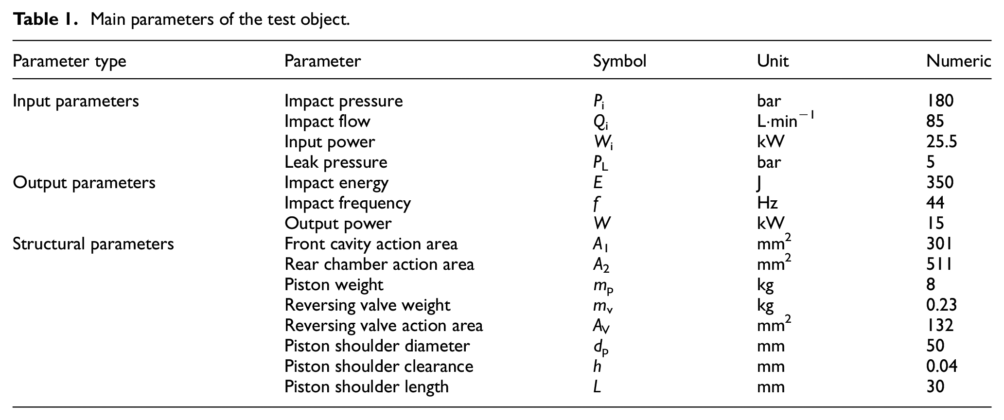
To enhance the comparability of the analysis, it is necessary to ensure the consistency of the input parameters. Specifically, the impact input pressure is 180 bar, the propulsion pressure is 45 bar, the buffer pressure is 70 bar, and the sufficient pumping station supply flow rate is more than 85 L/min. The only variable will be the accumulator gas pre-charge pressure, which will be adjusted to 120, 90, 80, 60, and 30 bar.
Determination of the volume of the high-pressure accumulator
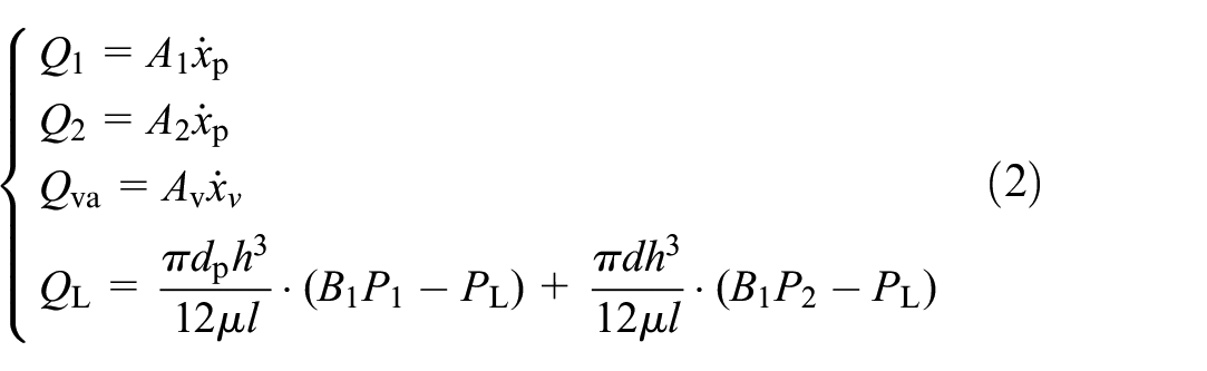
Combining with the principle and structural characteristics of unconstant-pressurized chamber rock drills, the required oil flow Qd mainly includes: the oil flow required for the piston movement, the oil flow for the movement of the reversing valve, and the flow of the leakage oil. 23 Ignoring the oil compression, the continuity equation for the flow rate required for piston movement is as follows:

Where Q1 and Q2 are the required hydraulic oil flow rate of the piston front and rear chambers respectively, L/min. Qva is the hydraulic oil flow rate of reversing valve movement, L/min. QL is the flow of the leakage oil, L/min. B1, B2, B3, and B4 are the state judgment quantities. Taking the return movement as the initial state, when the return commutation signal is completed before, B1 = 1, after completion, B1 = 0. When the return commutation is completed until the stroke commutation signal hole is opened, B2 = 1, after completion, B2 = 0. When the return commutation signal hole is opened, B3 = 1, when it is closed, B3 = 0. When the stroke commutation signal hole is opened, B4 = 1, when it is closed, B4 = 0.
Among them
Where
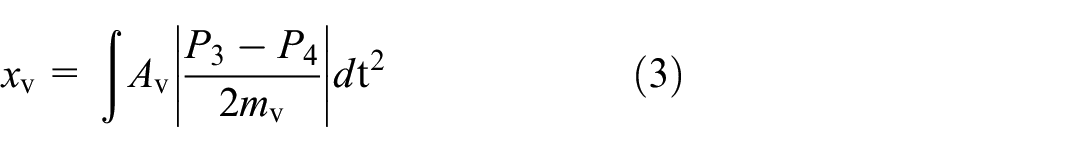
Formula (3) represents the displacement equation of the reversing valve.
Where
The rock drills piston movement process includes: return acceleration stage (

Flow of rock drill parts curve.
Figure 4 shows that:
(1) The traditional demand flow mainly obtains based on the front and rear chamber pressure calculation, the calculation is complex and highly disruptive external limitations. This method can more accurately obtain the value of each part of the flow and can reduce the interference of external factors.
(2) The proportion of flow in the front and rear chamber of the piston is much larger than oil flow for the movement of the reversing valve, and the flow of the leakage oil. In one cycle, V1, V2, Vva, VL are oil volume corresponding to Q1, Q2, Qva, QL, which account for 34.8%, 58.6%, 4.7%, 1.8% of the total flow. The reversing valve reversing and leakage account for 6.5% of the total flow. Q1:Q2:Qva: QL≈19:32:2.6:1.
In order to analyze the effect of the reversing valve and leakage factors on the total flow rate, the demand flow rate comparison is plotted in Figure 5

Demand flow comparison curve.
Figure 5 shows that:
(1) The flow envelope areas differ significantly. When ignoring for these two factors as consideration, the demand flow of 1−, 2−, 3−, 4+, 5+, 6+ positions are lower. In particular, in the position 1 lose one flow deficit situation. And over-all the sum of excess flow volume at 4, 5, 6 is greater than the sum of insufficient flow volume at 1, 2, 3.
(2) The flow conversion points t2, t4 moments are different, while t3 moments are basically the same. When ignoring for these two factors as consideration, the return stage of insufficient flow to excess flow transition moment t2.1 relative to t2 earlier, and the impact stage of insufficient flow to excess flow transition moment t4.1 relative to t4 moments earlier. This will result in a larger calculated excess flow volume and a smaller insufficient flow volume.
(3) The maximum excess flow volume and the maximum insufficient volume are different. When ignoring for these two factors as consideration, the maximum excess flow volume is larger, corresponding to 5 parts of the area and the volume is 5.3% larger. The maximum excess flow volume is smaller, corresponding to a 3-part area and the volume is 4.7% smaller.
Figure 6 shows that:
(1) The pump input flow rate Qa during the operation of the rock drill is a stable value, while the requirement of oil flow rate for the movement varies with the movement process throughout the movement cycle. For this reason, it is necessary to configure a high-pressure accumulator to ensure that the flow rate of the supply match the required flow rate of the main feed oil.
(2) The flow demand characteristics of the four motion cycles are as follows: 1) During the return acceleration cycle, the rock drills have a primary flow excess and a primary flow insufficient. In the initial stage, the piston movement speed is low and the primary feed oil flow required is less than the pump input flow. In the later stage, the piston movement speed is higher and the main feed oil required flow rate is greater than the pump input flow rate; 2) In the return brake cycle, the rock drill has excess flow. The direction of piston movement is opposite to the direction of main feed oil input. The oil is in excess; 3) During the stroke cycle, the rock drills have a primary flow excess and a primary flow insufficient. In the initial stage, the piston speed is low and the required flow rate of main feed oil is less than the pump input flow rate. In the later stages, the piston moves at a higher speed and the main feed requires more flow than the pump input; 4) In the impact cycle, the rock drills have a primary flow excess and a primary flow insufficient. In the initial stage, the piston speed is high and the main feed oil requires a flow rate greater than the pump input flow rate. In the later stage, the piston movement speed is lower and the required flow rate of the main feed oil is less than the pump input flow rate.
(3) In one motion cycle, there are two flow excess and two flow insufficient phases of the rock drills. Among them, the oil excess is the largest in the interval from t2 to t3, while the oil insufficient is the largest in the interval from t3 to t4.

Piston status and inlet oil demand flow curve.
Basing on Formula (4), the maximum excess flow rate V + and the maximum insufficient flow rate V- was calculated.

Assuming that the flow excess and flow insufficient are maintained by the accumulator, the maximum suction volume V
i
and maximum discharge volume V
o
of the accumulator are necessarily equal,
Formula (5) was the gas state equation of to the maximum working pressure Pamax and the minimum working pressure Pamin of the accumulator:

κ-adiabatic index. For N2, κ = 1.4–1.42;
The accumulator chamber pressure at 180 bar input pressure were obtained, the range of pressure fluctuation amplitude in each cycle was acquired as
Obtaining the accumulator gas chamber volume relation equation:

In order to ensure that the vibration of the accumulator diaphragm is uniform, it is generally believed that the diaphragm oscillates at half the volume position is preferred. Therefore, the accumulator volume Va is 2 times the volume of the gas chamber Va1.
When considering the reversal and leakage accumulator volume. Va = 2 × Va1 = 361.8–439.8 ml.
When ignoring the reversal and leakage accumulator volume. Va = 2 × Va1 = 291.2–351.8 ml.
Considering the difference of approximately 80 ml, which is about 5% smaller, the reversal flow rate and the leakage flow rate cannot be overlooked. By taking the median value of the accumulator volume range while accounting for commutation and leakage as the design value, it is concluded that the accumulator volume is 400 ml.
Analysis of the effect of gas pre-charge pressure on impact performance
Figure 7 illustrates the piston velocity curves derived from the time differentiation of piston displacement data obtained at various high-pressure accumulator gas pre-charge pressures. The peak of the piston velocity represents a sudden turning point in velocity. This peak is designated as the impact point, and the velocity at this point is extracted as the performance evaluation index.

Velocity diagrams at different inflation pressures curve.
As shown in Figure 7, the instability of the rock drill during actual movement complicates the direct comparison of impact point velocities across different high-pressure accumulator charging pressures. To facilitate an accurate comparison of impact energy, the instantaneous velocities of 10 groups of impact points are measured. The maximum and minimum values are excluded, and the average speed is calculated from the remaining eight impact points. Subsequently, the impact energy is computed based on this average speed. The results of the performance parameters are presented in Table 2.
Performance parameters at different high-pressure accumulator gas pre-charge pressure.

Figure 8 shows that:
(1) With the increase of high-pressure accumulator gas pre-charge pressure, the impact energy shows a trend of improvement. When the inflation pressure is from 30 bar to 80 bar, the impact energy is increased from 343.7 to 354.7 J. The impact energy is increased by 11 J. Each 10 bar of gas pre-charge pressure increase leads to 0.5 J impact energy increase. When the inflation pressure is from 80 bar to 120 bar, the impact energy is increased from 354.7 to 356.7 J. The impact energy is increased by 2.3 J. Each 10 bar of gas pre-charge pressure increase leads to 0.046 J impact energy increase, the effect of the increase in impact energy decreases to 22% between 30 bar and 80 bar.
(2) The maximum fluctuation range of impact frequency is only 0.03 Hz. Therefore, it is believed that the high-pressure accumulator gas pre-charge pressure has no effect on the impact frequency.
(3) For unconstant-pressurized chamber rock drills, the impact energy can be effectively improved by adjusting the gas pre-charge pressure of the high-pressure accumulator, provided that the impact frequency remains unaffected. The problem of impact powerlessness caused by the low impact energy can be improved. It is of great significance to improve the working efficiency of high-power rock drill in large-hole and hard-rock conditions.
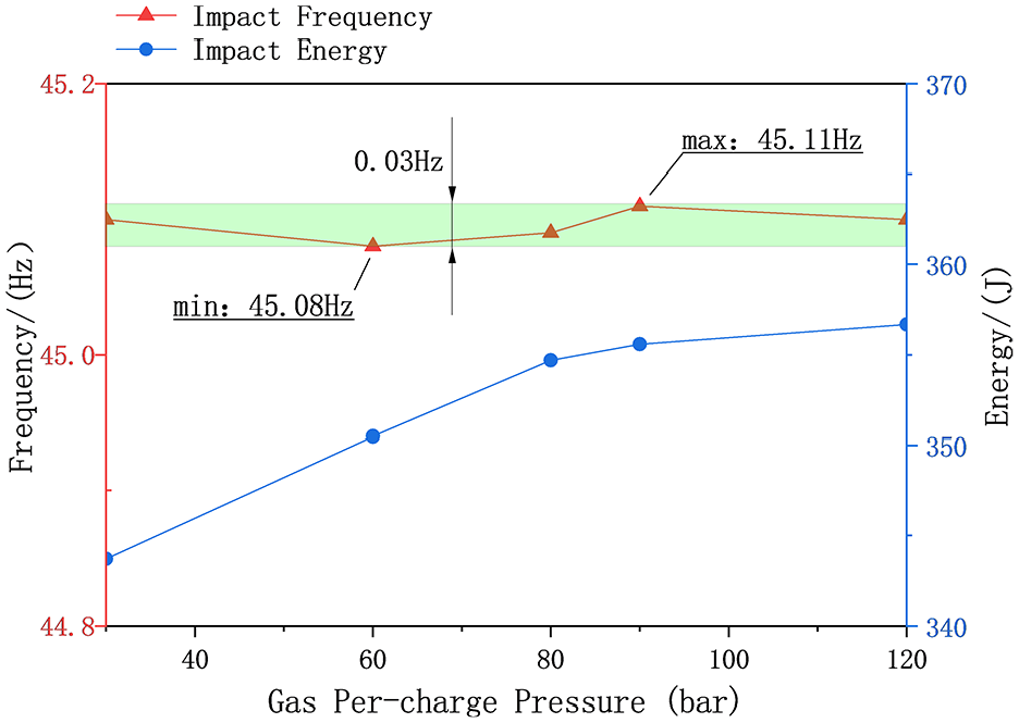
Relationship between impact energy, impact frequency and inflation pressure.
Analysis of the effect of dynamic coupling characteristics of high-pressure accumulators in shock systems
Analysis of the effect of gas pre-charge pressure on intrinsic performance
As shown in Figure 9, the high-pressure accumulator model was simplified and equated, drawing on the study of the dynamic characteristics of the bladder accumulator.

Simplified equivalent model of the accumulator structure.
Taking the oil in the pipeline and the oil cavity as the object of study and the air cavity as the load, the accumulator is equivalent to a spring damping system model.

Where Pi, Pa are the high-pressure accumulator input pressure and high-pressure accumulator gas chamber pressure, bar. A1, Aa are the high-pressure accumulator input chamber area and high-pressure accumulator chamber area, mm2. me, Ce, ke are the equivalent mass, equivalent viscous damping coefficient and equivalent stiffness of the accumulator. x is the diaphragm displacement, mm.
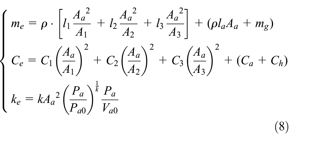
Where ρ is the oil density; m
g
is the mass of the diaphragm; k is the adiabatic coefficient, k = 1.4; Va0 and Va is the initial volume of the high-pressure accumulator;
Among them

Where Va0 and Va are the initial volume of the high-pressure accumulator and the actual gas chamber volume.
Let

Associative equations (7), (9), and (10) and Raschel transformations are obtained:

Since the change time of the gas cavity state is very short, the state can be approximated as an adiabatic state, the relation (12) is satisfied.

Where
Taylor expansion of equation (12) at the point (Pa0, Va0) and omitting the higher terms.

The Rasch transformations can be obtained

The transfer function which Pa as the output by equations (11) and (14).


Where ωn is the undamped intrinsic frequency. ζ is the system damping ratio.
When the diaphragm movement frequency
Based on equations (15), (16), (17), analyze the effect of high-pressure accumulator gas pre-charge pressure on the inherent characteristics of the accumulator in the impact system.
Figure 10 shows that:
(1) The intrinsic frequency of the high-pressure accumulator is negatively related to the gas pre-charge pressure, while positively related to the system pressure. They present the non-linear relationship characteristics;
(2) The equivalent damping of the high-pressure accumulator is positively correlated with gas pre-charge pressure, while negatively correlated with the system pressure. They also present the non-linear relationship characteristics;
(3) The system pressure and gas pre-charge pressure present typical opposing characteristics to the accumulator intrinsic characteristics. It is important to ensure the matching of system pressure and gas pre-charge pressure to maintain the stability of the accumulator.

Effect of accumulator inflation pressure on intrinsic performance.
Analysis of high-pressure accumulator diaphragm oscillation state
Calculate the high-pressure accumulator oil supply flow rate Q a at five different high pressure accumulator gas pre-charge pressures according to equation (18).
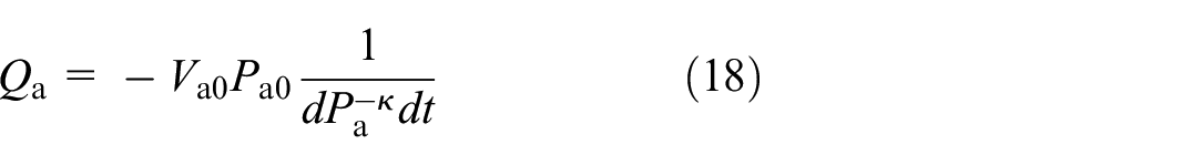
To obtain the accumulator oil supply flow variation curve, the pressure gas chamber pressure curve of the high-pressure accumulator was carried into the, as shown in Figure 10.
Figure 11 shows that:
(1) The higher gas pre-charge pressure, the greater the peak values of the accumulator discharge filling flow and storage suction flow.
(2) The higher gas pre-charge pressure, the more violent the accumulator diaphragm fluctuations in the return acceleration stage.
(3) The higher gas pre-charge pressure, the earlier the accumulator enters the energy storage stage in the return acceleration stage. It ensures higher energy storage to prepare for the next accumulator discharge, which is conducive to the improvement of the accumulator discharge effect in the stroke stage.

Accumulator flow comparison.
Further, the initial moment is taken as the starting point of the return movement after impact. Figure 12(a), (d), (g), (j), and (m) show the air cavity volume of the diaphragm in one cycle at the corresponding five sets of high-pressure accumulator gas pre-charge pressure. Figure 12(b), (e), (h), (k), and (n) are plots of the accumulator flow rate of the diaphragm in one cycle at the corresponding five sets of high-pressure accumulator gas pre-charge pressure. By comparing the time series diagram of gas chamber volume and the time series diagram of accumulator flow rate at the same input flow rate and pressure, it is found that there is a big difference in the return stage.

Diaphragm status diagram: (a) 120bar gas-chamber volume, (b) 120bar accumulator flow, (c) 120bar phase diagram, (d) 90bar gas-chamber volume, (e) 90bar accumulator flow, (f) 90bar phase diagram, (g) 80bar gas-chamber volume, (h) 80bar accumulator flow, (i) 80bar phase diagram, (j) 60bar gas-chamber volume, (k) 60bar accumulator flow, (l) 60bar phase diagram, (m) 30bar gas-chamber volume, (n) 30bar accumulator flow, and (o) 30bar phase diagram.
To better understand dynamic coupling characteristics of the high-pressure accumulator and the impact system, and to show the dynamic response evolution law of the diaphragm under different gas pre-charge pressure more clearly, the figures with the volume of the gas chamber and the accumulator flow rate as the analysis parameters were plotted. Taking the starting point of the return motion as the initial position and taking the points in sequence at the time interval by one shock cycle, the dynamic phase diagram was obtained at this inflation pressure.
As shown in Figure 12(o), from the initial starting point to the next folding bifurcation, that the accumulator diaphragm state returns to initial state, for the period-one motion state, P-1-A-1.
As shown in Figure 12(c), (f), (i), and (l), from the initial starting point to the next folding bifurcation, the accumulator diaphragm did not return to the initial state. Instead, the diaphragm returned to the initial state after two bifurcations appeared, so that the diaphragm oscillated twice in one shock cycle, for the period-one motions state, P-1-A-2. And with the increase of gas pre-charge, the period-doubling bifurcation gradually strengthens.
In conclusion, the present system exhibits typical contact nonlinear characteristics, which is fully proved by the evolution law of its dynamical behavior.
Conclusion
This paper investigates the coupling characteristics of the accumulator and the impact system, and designs a series of impact performance tests utilizing multi-signal synchronous acquisition. Based on the test data, a method for determining the accumulator volume is proposed, and an analysis of the accumulator inflation pressure is conducted. The effects on impact performance and diaphragm state provide valuable insights for the application and parameter setting of high-pressure accumulators in unconstant-pressure chamber rock drills. This research holds significant importance for addressing the issue of insufficient impact force in high-power hydraulic rock drills.
(1) During the experiment on simultaneous acquisition and analysis of multiple signals, a precise method for calculating the demand flow rate of rock drills was proposed. The results indicate that the difference in accumulator volume, when considering versus ignoring the reversal and leakage of the accumulator volume, is approximately 5%.
(2) Through means of phase diagrams, high-pressure accumulator diaphragm oscillation states were analyzed. The folding bifurcation state of the diaphragm under different inflation pressures were analyzed. With the increase of gas pre-charge, the bifurcation point develops from single-cycle P-1-A-1 state to double-cycle P-1-A-2 state. Additionally, the intensity of the period-doubling bifurcation gradually strengthens, demonstrating a typical nonlinear characteristic.
(3) With the increase of the high-pressure accumulator gas pre-charge pressure, the impact energy gradually increases. The gas pre-charge from 30 bar to 120 bar increases the shock power and shock energy by 3.8%. After the gas pre-charge pressure reaches 80 bar, the trend of impact power and impact energy increase slows down. Considering the fatigue life of the diaphragm, the optimum choice of high-pressure accumulator gas pre-charge pressure is 80–90 bar.
(4) This article conducts research and analysis on the coupling characteristics of the accumulator and the impact system. By using gas pre-charge pressure as a focal point, the study experimentally analyzes its effects on impact performance and coupling characteristics. Additionally, by formulating the accumulator state equation, this study analyzes the effects of charging pressure and system pressure on the natural frequency and equivalent damping of the accumulator Future research will further explore the effects of oil pressure fluctuations caused by reversing on these coupling characteristics.
Footnotes
Acknowledgements
First and foremost, we would like to express our heartfelt gratitude to all those who have contributed to the successful completion of this journal. Furthermore, we are also extremely grateful to our esteemed reviewers for their thorough evaluation, constructive feedback, and expert guidance throughout the peer review process. Last but not least, we thank all the editors for their dedication, hard work, and commitment to advancing knowledge in our field.
Handling Editor: Sharmili Pandian
Author contributions
Xiang Tian: Conceptualization, Methodology, Software, Validation, Writing – original draft. Fei Ma: Funding support and Review & Editing. Xiao-guang Geng: Funding support and Review. Wei-hang Xi: Investigation, Data curation. Zi-hang Zhang: Literature review.
Declaration of conflicting interests
The author(s) declared no potential conflicts of interest with respect to the research, authorship, and/or publication of this article.
Funding
The author(s) disclosed receipt of the following financial support for the research, authorship, and/or publication of this article: This work was supported by National Key R&D Program (2021YFB3401502), The Fundamental Research Funds for the Central Universities (FRF-TP-19-040A1), Natural Science Foundation of China (52275108).