
Abstract
To optimize the frame of a sightseeing vehicle, this paper proposes a multi-objective topology optimization method combining Analytic Hierarchy Process (AHP) and topology optimization. Firstly, the edges of the unmanned sightseeing car are statically analyzed. The rectangular steel frame structure of the original frame is replaced with square plates, the basic model of the unmanned sightseeing car frame is established, and a single-objective topology optimization mathematical model of the frame is established to optimize the topology design of the frame. Then, in order to design a frame structure that meets all the working conditions at the same time, a mathematical model of multi-working condition topology optimization is established, and the weights of each working condition are determined by using AHP, and the multi-working condition topology optimization design of the frame is carried out. Finally, a comparison of the comprehensive performance of the frame before and after optimization shows that the proposed method enables the optimized frame to meet the strength requirements under various working conditions, resulting in a weight reduction of 16.5 kg.
Introduction
The problems with unmanned sightseeing vehicles, which belong to new energy vehicles, are heavy vehicle mass and poor driving range. In addition, the frame design of unmanned sightseeing vehicles is based on experience. Since conservative design may cause a waste of materials, it is necessary to adopt a topology optimization method to optimize the structure layout of the frame.
Researchers have carried out much research using topology optimization methods. Zhao et al. 1 proposed the multi-objective topology optimization of automotive powertrain mounting support considering various static and dynamic conditions. They adopted the compromise programing method to optimize the multi-objective and multi-stiffness topology of powertrain mounting support under static loading conditions. According to the optimization results, the final mounting bracket was reconstructed to achieve the purpose of lightweight design. Liu et al. 2 proposed a multi-objective topology optimization strategy for electric truck frames combining the hybrid decision method of orthogonal test design (OTD) and the Analytic Hierarchy Process (AHP) for the frame lightweight design of electric truck frames. The topology optimization design of the electric truck frame was carried out under the constraint of each static and dynamic working condition, which improved the utilization rate of the frame materials and the structural performance. Liu et al. 3 proposed a fuzzy multi-objective topology optimization method based on fuzzy satisfaction variable weight coefficients. The fuzzy membership function was used to determine the fuzzy satisfaction degree of the frame optimization objective, the weight of each working condition was determined according to the variable weight method, and the fuzzy multi-objective topology optimization was carried out. After optimization, the frame stiffness increases by. 4 7%, and the first-order natural frequency increases by 5.6%. Zhu et al. 3 established a mathematical model of multi-objective topology optimization for spherical heads with the compromise programing method under the constraint of each static load condition. They realized the lightweight design of spherical heads. Zhao et al. 5 adopted the topology optimization method to optimize a 12000KN fining machine frame. The optimization results show that compared with the original frame, the volume is reduced by 13.66%, and the performance is slightly improved. Wu et al. 6 took the volume of the frame of the compression shear testing machine as the constraint condition. They adopted the variable density method of topology optimization to carry out topology optimization on the frame of the compression shear testing machine. After optimization, the frame met the static strength and stiffness requirements, and the weight was reduced by 14.5%. Li et al. 7 proposed a mathematical model for lightweight optimization design and established a geometric model for the initial design of the front column. The results show that the weight of the front column can be reduced by 60.4%. Xie et al. 8 designed the hydraulic valve block lightweight based on the multi-objective topology optimization method. After optimization, the maximum stress of the final design is 542.9 MPa, which meets the requirements of material strength and reduces the weight by 68.9%. Ma et al. 9 adopted multi-operating condition topology optimization to optimize the design of the turnover frame. By comparing the original and optimal turnover frame’s finite element results, it was shown that the total mass of the optimal scheme was reduced by 0.21% while maintaining better stiffness and durability. Li et al. 10 developed a new indenter structure using topology and thickness optimization. Compared with the traditional indenter structure, the total mass is reduced by 31.8%, improving performance. Zhu et al. 11 proposed an adaptive PID controller based on GOA to improve the control loop of traditional 3D printing, establishing design criteria such as settling time, overshoot, and rise time. This optimization minimizes overall error, particularly surface errors. Zhao et al. 12 employed a combination of multi-objective topology optimization and Analytic Hierarchy Process (AHP) to optimize the structural design of the large gear in the directional drilling rig transmission system, achieving a weight reduction of 25.3%. Ma et al. 13 proposed a dual optimization of the Formula Racing frame using the Variable Density Method and the Articulated Variable Method, which resulted in a successful weight reduction of 12.8%.
Building on previous research, this paper focuses on the frame of a sightseeing vehicle and proposes a multi-objective topology optimization design method for the frame under multiple conditions. (1) A multi-objective topology optimization strategy was developed based on the Analytic Hierarchy Process (AHP). Unlike objective weighting methods for determining topology optimization weights, our study emphasizes the development of a strategy that combines subjective weighting with multi-objective topology optimization. (2) For the complex chassis structure of welded steel, a multi-objective topology optimization strategy based on AHP is introduced. Optimization of chassis dimensions is based on variables with higher weights, further enhancing the overall structural performance.
The rest of this paper is as follows: firstly, the static analysis of the unmanned sightseeing vehicle frame is carried out. Then the topology optimization base model of the unmanned sightseeing vehicle is established, and the topology optimization design of the single working condition is carried out. Then, in order to meet the requirements of four working conditions at the same time, a multi-working condition topology optimization mathematical model was established, the weight of four working conditions was determined by AHP, and the frame of the unmanned sightseeing vehicle was optimized by variable density topology optimization design, and the frame model was re-established according to the optimization results. Finally, a comparison of the frame’s performance before and after optimization demonstrates that this method can enhance the overall structural performance.
Modeling and analysis
This paper takes the prototype frame of an unmanned sightseeing vehicle as the research object. The frame structure of the unmanned sightseeing vehicle is welded with rectangular steel with a wall thickness of 3–5 mm, which is divided into three parts: front section, middle section, and rear section. The total frame length is 8500 mm, and the weight is 1145.7 kg. The physical picture of the unmanned sightseeing vehicle is shown in Figure 1.

Physical picture of unmanned sightseeing vehicle.
According to the existing two-dimensional CAD drawings of the frame of the unmanned sightseeing vehicle, the three-dimensional model of the frame was established using SolidWorks software. The model was imported into Workbench software and pre-processed in the Design Molder module. After processing, grid division is carried out on the frame. After grid division, the frame has a total of 2,476,444 nodes and 1,267,305 grid units. The finite element model of the frame of the unmanned sightseeing vehicle is shown in Figure 2.

Finite element model of the frame of unmanned sightseeing vehicle.
Static analysis
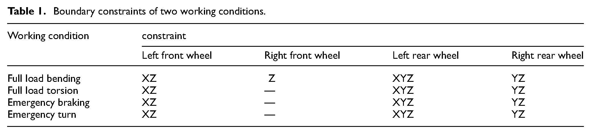
When the unmanned sightseeing vehicle is driving on closed roads such as industrial parks or ports, static analysis should be considered under four common working conditions, including full-load bending, full-load torsion, emergency braking, and emergency turning. The boundary constraints of the four working conditions are shown in Table 1.
Boundary constraints of two working conditions.
The frame of the unmanned sightseeing vehicle mainly bears passengers, seats, battery boxes, and electrical parts. According to the actual distribution, these loads are added to the frame, as shown in Figure 3. The load quality parameters are shown in Table 2.
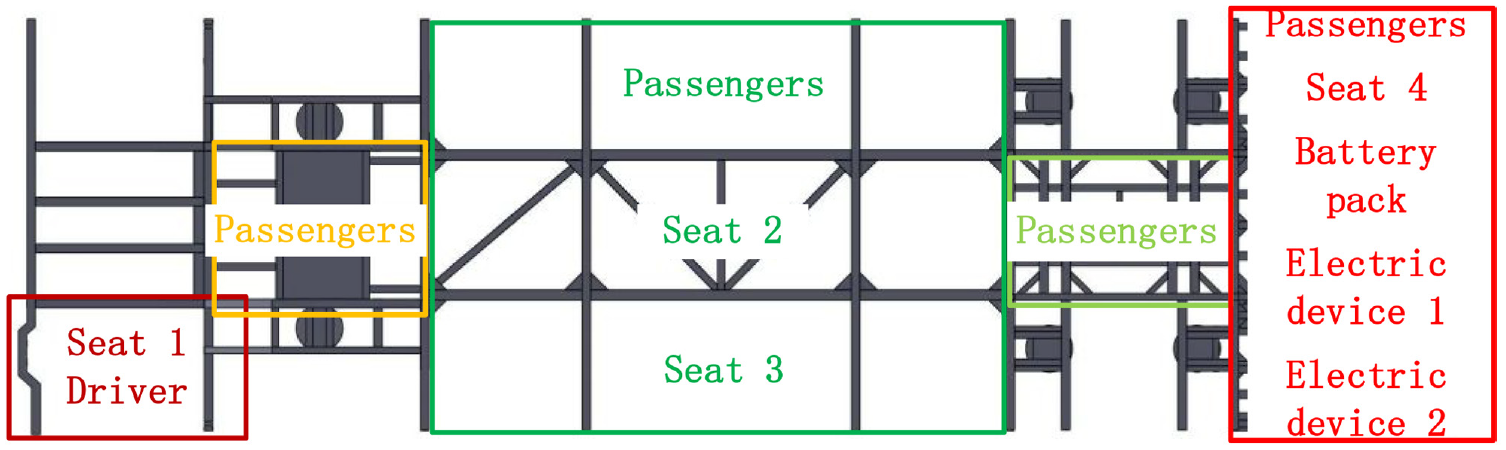
Load distribution diagram.
Load mass parameters.

Static analysis of full load bending condition
The full load bending condition is one of the typical working conditions of the unmanned sightseeing vehicle, which mainly simulates the main stress condition of the full passenger car. The dynamic load on the road surface is complex and often presented in a combined manner, and the actual force can be measured by multiplying the load by the dynamic load coefficient during the analysis. The dynamic load factor can be expressed as:

Among them:
According to the boundary constraint conditions of full load bending condition, the corresponding four-wheel position of the frame was constrained, respectively, and gravity was added. The load on the frame is affected by the dynamic load coefficient, which is 2 14 in full-load bending conditions. According to the calculation of equation (1) above, the dynamic load factor under 4 different working conditions is shown in Table 3.
Dynamic load coefficient of each working condition of the frame.

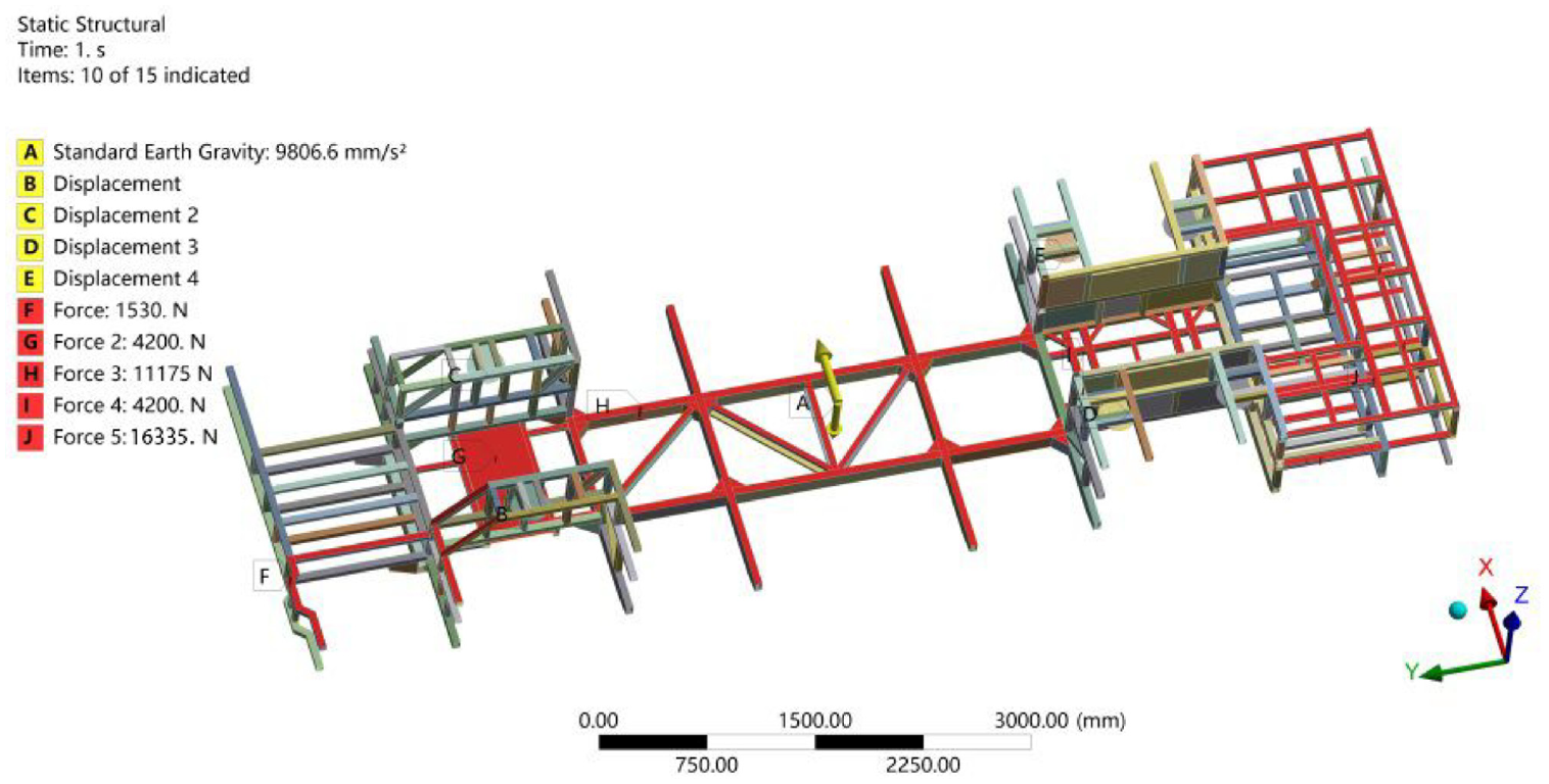
The load loading is shown in Figure 4, A is the standard gravitational acceleration of the Earth in the negative direction of the Z-axis. B, C, D, E are respectively the displacements of the left front wheel, the right front wheel, the left rear wheel, and the right rear wheel according to Table 1. In the case of full load, for example, the left front wheel constrains the displacement in the X and Z directions. The right front wheel constrains the displacement in the z-direction. The left rear wheel constrains the displacement in the x, y, and z directions. The right rear wheel constrains the displacement in the Y and Z directions. The F load in the figure indicates that a driver and a seat in position F weigh 102 kg. According to the load factor of 2, the force is 2040N. The G load means that there are 4 passengers in the G position, the weight is 280 kg, and the load should be 5600 N. Similarly, the I load is also four passengers, and the size is also 5600N. The H load represents a weight of 725 kg for seats 2 and 3 and 8 passengers. The J load is a battery box pack, electrical device 1, electrical device 2, a seat for 4 people and a weight of 4 passengers 1089 kg. And the analysis results are shown in Figure 5.

Frame loading diagram of unmanned sightseeing vehicle (full load bending condition).

Finite element analysis results under full load bending condition: (a) displacement nephogram; (b) stress nephogram.
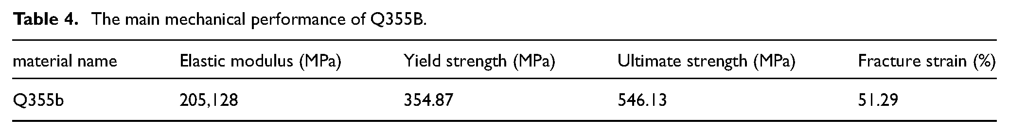
As shown in Figure 5(a), the maximum displacement of the frame of the unmanned sightseeing vehicle under full load bending conditions is 4.23 mm. The largest deformation mainly occurs at the left of the rear section of the frame, which is consistent with the actual situation. This is because the battery box group has a large mass and is distributed in a concentrated way, resulting in a large displacement. As can be seen from Figure 5(b), the maximum stress value of the frame of the unmanned sightseeing vehicle under full load bending conditions is 264.13 MPa, the material used for the frame is Q355b, and the maximum yield strength is 355 MPa. The main mechanical performance of Q355B is presented in Table 4.It can be seen that the maximum stress value of the frame is less than the yield strength of the material, and the frame structure is safe without fracture.
The main mechanical performance of Q355B.
Statics analysis of full load torsional condition
According to the boundary constraint conditions of full-load torsion condition, constraints were imposed on the corresponding four-wheel positions of the frame, respectively, and gravity was added. The dynamic load coefficient of the applied load was 1.5, 14 and the load loading was shown in Figure 6. The analysis results are shown in Figure 7.

Frame loading diagram of unmanned sightseeing vehicle (full load torsional condition).
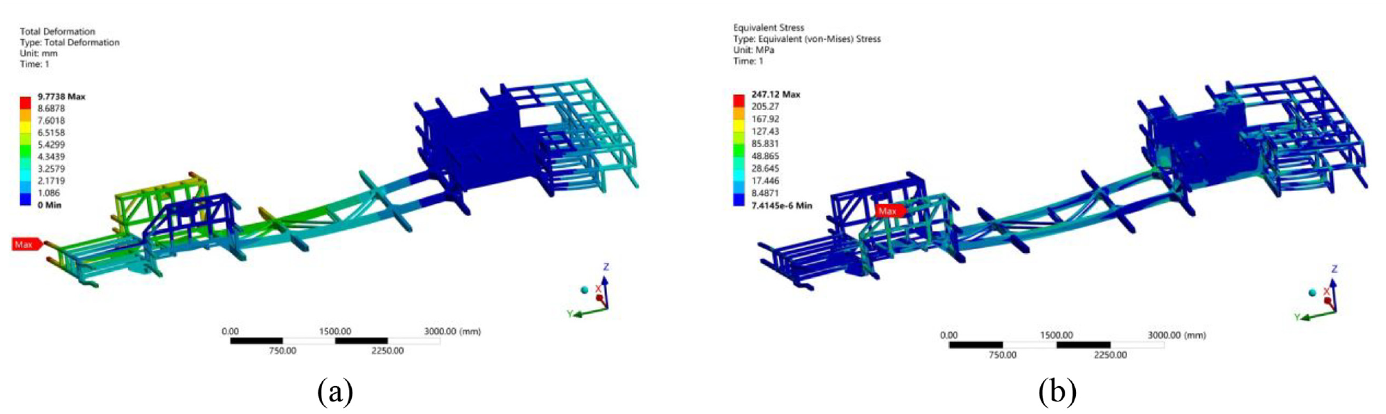
Finite element analysis results under full load torsional condition: (a) displacement nephogram; (b) stress nephogram.
As seen from Figure 7(a), the maximum displacement of the frame under full-load torsion is 9.77 mm, and the maximum deformation occurs at the front end of the frame. As seen from Figure 7(b), the maximum stress value of the frame under full load torsion condition is 247.12 MPa, the material used for the frame is Q355b, and the maximum yield strength is 355 MPa. It can be seen that the maximum stress value of the frame is less than the yield strength of the material, and the frame structure is safe without fracture.
Statics analysis of emergency braking condition
According to the boundary constraint conditions of emergency braking conditions, constraints were imposed on the corresponding four-wheel position of the frame, gravity was added, and 0.7gravitational acceleration was added in the negative direction of the Y-axis to simulate the state of the vehicle deceleration. The dynamic load coefficient of the applied load was 1.5, 14 and the load loading was shown in Figure 8. The analysis results are shown in Figure 9.

Frame loading diagram of unmanned sightseeing vehicle (emergency braking conditions).

Finite element analysis results under emergency braking conditions: (a) displacement nephogram; (b) stress nephogram.
As seen from Figure 9(a), the maximum displacement of the frame under emergency braking conditions is 3.44 mm, and the maximum deformation occurs at the last end of the frame. As seen from Figure 9(b), the maximum stress value of the frame of the unmanned sightseeing vehicle under emergency braking conditions is 205.88 MPa, which is less than the yield limit of the frame material of 355 MPa. The safety factor of the frame under this condition is relatively high, and the frame will not break.
Statics analysis of emergency turning condition
According to the boundary constraint conditions of emergency turning conditions, constraints were imposed on the corresponding four-wheel positions of the frame, gravity was added, and 0.4 gravitational acceleration was added in the X direction to simulate the vehicle’s state when turning. The dynamic load coefficient of the applied load was 1.5, 14 and the load loading was shown in Figure 10. The analysis results are shown in Figure 11.
Frame loading diagram of unmanned sightseeing vehicle (emergency turning condition).

Finite element analysis results under emergency turning conditions: (a) displacement nephogram; (b) stress nephogram.
It can be seen from Figure 11(a) that the maximum displacement of the frame under emergency turning conditions is 3.25 mm. As seen from Figure 11(b), the maximum stress value of the frame of the unmanned sightseeing vehicle under emergency turning conditions is 201.55 MPa, which is less than the yield limit of the frame material, 355 MPa. The safety factor of the frame under this condition is relatively high, and the frame will not break.
Single working condition topology optimization
Establishment of topology optimization base model
In the process of establishing the topology optimization model of unmanned sightseeing car frame. Since the frame structure of the unmanned sightseeing vehicle is welded from hollow rectangular steel, the welding process requirements are cumbersome and it is not easy to change the structure, and many on-board device assemblies need to be mounted on the frame, such as seats, battery box sets, electrical components, etc., which limits the optimization of the frame structure to a certain extent. The topology optimization base model does not need to build up a detailed structure, only the dimensions of the topology optimization base model need to include the final structure. Taking the above conditions into account, it was decided to replace the original structure with rectangular plates in the front, middle and rear structure of the frame.
In the front section, two plates with 960 mm × 970 mm × 40 mm dimensions were used to replace the original rectangular steel structure. At the back of the front, two 1195 mm × 235 mm × 50 mm plates were used to replace the original rectangular steel structure. The middle adopts the size of 2380 mm × 3320 mm × 50 mm plates instead of the original structural skeleton. The rear upper layer uses two 588 mm × 715 mm × 40 mm, two 791 mm × 440 mm × 40 mm, and a 693 mm × 440 mm × 40 mm plate instead of the original structure. The lower part of the rear adopts a 693 mm × 440 mm × 40 mm and two 735 mm × 440 mm × 40 mm plates instead of the original structure. These plates are taken as topology optimization design optimization areas, and other areas are non-optimization areas. The topology optimization base model of the frame of the unmanned sightseeing vehicle is shown in Figure 12.

Basic topology optimization model.
Optimization results
In this paper, the topology optimization design of the frame under a single working condition is first carried out, aiming at minimizing compliance, taking the density of structural units as the design variable and volume fraction as the constraint condition. The mathematical model of the topology optimization under single working condition based on the penalty theory (SIMP) is as follows15–17:

Among them: ρ is the design variable; K is the stiffness matrix of the structure; U is the stiffness matrix of displacement; Design variable ρ i represents the density of the i-th element; u i represents the displacement vector of the i-th element; k0 is the element stiffness matrix before structural optimization; V(ρ) and V represent the volume of the structure and the specified volume respectively; 1 and ρmin are the upper and lower limits of the design variable ρ.
Before topology optimization of the unmanned sightseeing vehicle frame, relevant parameters need to be set in the Topology optimization module of Workbench software, including defining the optimization area, setting constraints, defining an objective function, etc. In this paper, the above rectangular plate is set as the optimization area, the other areas are set as the non-optimization area, the constraint condition is the boundary condition of each working condition, and the objective function is to satisfy the minimum frame flexibility. Variable density topology optimization is adopted; the optimized volume fraction is 0.1, and the penalty coefficient is 3. Figure 13 shows the topology optimization results in a single working condition.

Single condition topology optimization results. (a) full load bending condition; (b) full load torsional condition; (c) emergency braking condition; (d) emergency turning condition.
As can be seen from the above results of single-working condition topology optimization design, the stress of the frame is different under different working conditions, and the constraints are different. Hence, the obtained topology optimization results are also different. As shown in Figure 13, the gray areas are the stressed areas that need to be retained and the yellow areas are the areas that can be removed. The upper right portion of each topology optimization map is the upper rear area frame in Figure 12. The gray areas need to be reinforced with additional triangular reinforcement. It can be seen that the optimization position of each working condition is different, and the reconstruction of the new frame according to the single-condition topology optimization results cannot meet the requirements, which requires the design of the frame structure for multiple-condition topology optimization. At the same time, according to the above topology optimization results, it can be seen that the parameters in the topology optimization process are set correctly, and the generated results have a clear outline, which provides the basis for the multi-condition topology optimization design.
Multi-working condition topology optimization
Establishment of a mathematical model of multi-working condition topology optimization
In this paper, the compromise programing method is adopted to carry out multi-condition topology optimization for the frame of the unmanned sightseeing vehicle. The minimum flexibility of the frame structure is taken as the objective function, and the volume of the frame structure is taken as the constraint condition to find the frame structure with the minimum deformation under multiple conditions. The multi-condition topology optimization mathematical model of the frame based on the variable density method is as follows18,19:

Among them: ρ is the design variable; q is the penalty factor, q > 1; ω k is the weight of the objective function in the kth operating condition, where ω1 +ω2+… +ωk = 1; C k (ρ) is the flexibility objective function of the kth working condition; C k max and C k min represent the maximum and minimum values of the compliance objective function in the kth operating condition; m is the number of working conditions; n is the total number of units in the subdomain; ρmin and ρmax for the minimum and maximum values of the design variable. vi represents the volume of the i-th unit, ρi denotes the design variable of the i-th unit, and v denotes the average value across all units. The entire optimization process should adhere to the principle of maintaining constant volume while allowing for varying density.
As can be seen from the objective function of multi-condition topology optimization above, each condition needs to be assigned a corresponding weight, and the weight assigned to each condition is the same or inaccurate according to artificial determination, so the weight of each condition needs to be judged by comprehensive evaluation method. Analytic hierarchy Process (AHP), as a classical comprehensive evaluation method, can help determine the corresponding weight of each condition.
The theory of analytic hierarchy process
The methods to determine the weight of each condition are mainly divided into artificial subjective determination and comprehensive evaluation method determination. 20 The subjective determination of the weight value will have a greater impact on the result but also greatly test the knowledge reserve and design experience of engineering designers. In order to reduce the interference of human factors and reduce the requirements of engineering designers, the analytic hierarchy process is used to determine the weight value of each working condition. Analytic hierarchy process (AHP) is a comprehensive evaluation method; its main process is as follows:
(1) Construct the judgment matrix
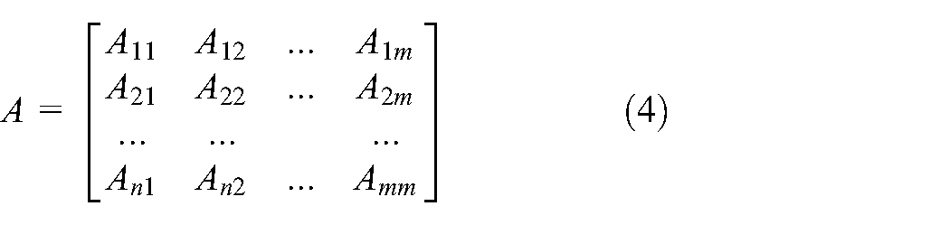
According to the empirical judgment, by comparing the relative importance of the indicators, construct the judgment matrix A = (A ij )m×m in this judgment matrix, m represents the number of evaluation indicators, A ij is the importance degree of evaluation index i relative to evaluation index j. The judgment matrix is as follows:
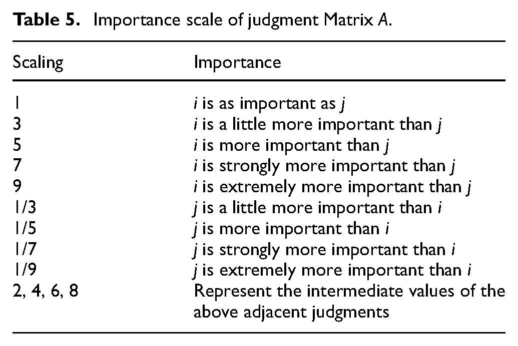
According to the determined relative importance, a given measure is needed to measure the degree of this importance. Table 5 shows the importance measure, where the importance value combined with the determined relative importance can construct a specific judgment matrix A.
(2) Calculate the consistency ratio


Importance scale of judgment Matrix A.
In order to ensure the Consistency of the established judgment matrix, the Consistency ratio (CR) is quoted to verify whether the judgment matrix satisfies the consistency principle; if the judgment matrix is inconsistent, the judgment matrix needs to be re-established. When the consistency ratio satisfies equation (4), it indicates that the judgment matrix is reasonable.
Where CI is the consistency index, m is the number of evaluation indicators, λmax is the maximum eigenvalue of the judgment matrix A, and RI is the average value of the random consistency index, whose value is shown in Table 6.
(3) Calculate the weight of each evaluation index
Average random consistency index.

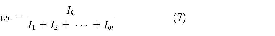
Suppose the vector I = (I1, I2…, I m )T is to determine the maximum eigenvalue λ of matrix Amax, the corresponding eigenvector, then the weight of the kth evaluation index is:
Where I k is the kth value in the eigenvector I.
Determine the weight by analytic hierarchy process
(1) Construct the judgment matrix
Firstly, we employed a pairwise comparison method to assess the importance between operating conditions, resulting in a pairwise comparison matrix. According to the judgment, full load bending condition is slightly more important than full load torsion condition, full load bending condition is more important to emergency braking condition, and full load bending condition is very important to emergency turning condition. Full load torsion condition is more important than emergency braking condition and emergency turning condition. Emergency braking condition is slightly more important than emergency turning condition. Based on this, the corresponding importance value is obtained by referring to Table 6, and the judgment matrix A is constructed as follows:

(2) Calculate the consistency ratio of judgment matrix A
In order to verify whether the established judgment matrix A meets the requirements, it is necessary to calculate its consistency ratio. In this paper, the maximum eigenvalue of the established judgment matrix A is λmax is 4.2281, the number of working conditions m is 4, and the consistency index CI is 0.0760 by substituting it into equation (5). According to Table 6, the average random consistency index RI is 0.9, and the above values are substituted into equation (4) to calculate CR = 0.0760 / 0.9 = 0.0845 < 0.1.
It can be seen from the calculation that the consistency ratio of the judgment matrix A is less than 0.1, indicating that the established judgment matrix A is reasonable.
(3) Calculate the weight of each working condition
In this paper, the eigenvector corresponding to the maximal eigenvalue λmax of matrix A is determined as I = (0.8651, 0.4678, 0.1605, 0.0838)T, By substituting the four characteristic vectors into equation (6), we can compute the weights of the four operating conditions. The weight of the four working conditions can be obtained as w1=0.5485, w2=0.2966, w3=0.1018, w4=0.0531. That is, the weight of the full load bending condition is 0.5485, the full load torsion condition is 0.2966, the emergency braking condition is 0.1018, and the emergency turning condition is 0.0531, as shown in Table 7.
Weight allocation table.

Multi-working condition topology optimization results
According to the established mathematical model of multi-working condition topology optimization, the weight of each working condition was substituted into the mathematical model of topology optimization, and the topology optimization design of the frame base model of the unmanned sightseeing vehicle was carried out by using the variable density topology optimization method. As shown in Figure 14, the gray areas represent stress-bearing areas that need to be retained, while the yellow areas can be removed. The upper right of the topology optimization diagram corresponds to the upper rear portion of the chassis in Figure 12. The gray areas require additional triangular weldment reinforcement. And the optimization iteration is shown in Figure 15, after the 36th iteration, the objective tends to converge.

Results of multi-operating condition topology optimization.

Iteration diagram of topology optimization in multiple working conditions.
According to the results of topology optimization in multi-working conditions, the frame was redesigned. Referring to the wall thickness of the rectangular steel of the original frame, Q355b was still used as the material, and the same type of rectangular steel was used as the optimized contour. As shown in Figure 16, the frame needs to be redesigned. As indicated in Figure 14, it is evident that the front part of the frame does not require as many rectangular steel plates, thus necessitating a reduction in the number of steel plates at the front of the frame. The front of the frame is optimized from the original two rectangular steel pieces to a rectangular steel piece in the middle. The wall thickness of the rectangular steel pieces is consistent with that of the original frame.

Comparison of front frame optimization before and after. (a) Optimize the front frame; (b) Optimize the rear frame.
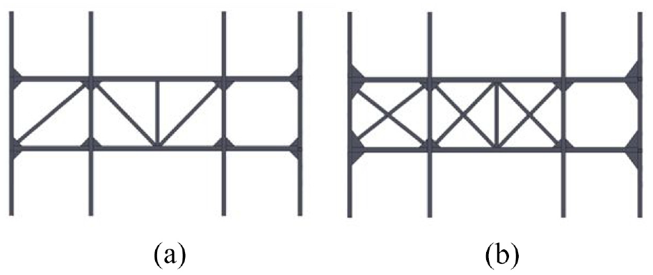
As shown in Figure 17, there are three vertical rectangular steels at the front and back of the frame. The topology optimization results show that the distance between the three regions of stress concentration is fixed. Therefore, the optimized frame still uses the same three rectangular steel plates. However, according to the topological optimization results, the positions of the three rectangular steels need to be adjusted to redesign the structure there.

Comparison of the front and rear of the frame before and after optimization. (a) Optimize the front frame; (b) Optimize the rear frame.
As shown in Figure 14, according to the results of topology optimization, there is a large amount of material between the outline of the middle of the frame and the front and rear parts of the frame, so it is necessary to redesign the triangle steel here. The original frame uses a section of 100 mm × 100 mm triangle steel; according to the results of topology optimization, the dimensions of the triangular steel should be designed larger to have better mechanical properties, it is changed into a section of 150 mm × 200 mm triangle steel; the new triangle steel is shown in Figure 18.

Comparison before and after optimization of middle frame triangle steel. (a) Optimize the front frame; (b) Optimize the rear frame.
The middle part of the original frame is composed of two small rectangular steel supports with the same direction up and down. From the topology optimization results under full load torsion conditions, it is evident that when any wheel overhangs, this side of the frame experiences higher stresses. Therefore, the center of the frame should be designed as a symmetrical structure. The new frame design consists of multiple small rectangular steel structures with additional intersecting rectangular steel in the center. The top and bottom are arranged opposite each other to meet the suspension requirements on both sides. The thickness of the rectangular steel walls was the same as the original frame. The newly generated structure is shown in Figure 19.
Comparison before and after optimization of the middle frame. (a) Optimize the front frame; (b) Optimize the rear frame.
The upper layer of the rear of the original frame adopts the cross-structure design. According to the results of topology optimization in multiple working conditions, the load of the rear of the frame is small, and the cross-structure design is a waste of materials. Therefore, according to the results of topology optimization, the rectangular steel of the cross structure is removed, and there is material distribution at the front end, where the triangular steel is added for reinforcement, and the new structure formed is shown in Figure 20.

Comparison before and after optimization of the upper rear frame. (a) Optimize the front frame; (b) Optimize the rear frame.
The lower part of the rear of the original frame is an H-shaped structure design. According to the results of topology optimization, there is no material that can be removed from this part, so the same structural design with the original frame is maintained, as shown in Figure 21.

Comparison before and after optimization of the lower rear frame. (a) Optimize the front frame; (b) Optimize the rear frame.
According to the results of multi-operating condition topology optimization, the structure of the topology optimization area was redesigned. According to the above-optimized design structure, a new frame of the unmanned sightseeing vehicle is constructed, and its structure is shown in Figure 22.

Frame after topology optimization.
Comparison of frame performance before and after topology optimization
To verify the overall performance of the newly designed unmanned sightseeing vehicle frame, static analysis, and modal analysis were carried out on the newly designed frame,21–24 in which the boundary conditions and load application conditions of the four operating conditions in the static analysis were the same as those of the original frame.
The statics analysis results of the frame after topology optimization under full load bending conditions are shown in Figure 23.

Finite element analysis results of the optimized frame under full load bending condition: (a) displacement nephogram; (b) stress nephogram.
As can be seen from the Figure 23, the maximum stress value of the topologically optimized frame under full load bending conditions is 261.59 MPa, which is less than the allowable stress of the material 355 MPa. However, compared with the maximum stress value of the original frame, the maximum stress point still appears at the joint of the battery box group support. The maximum displacement of the frame is 4.17 mm, and the maximum displacement point appears at the rear end of the frame.
The static analysis results of the frame after topology optimization under full load torsion are shown in Figure 24
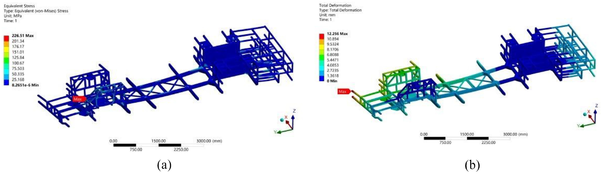
Finite element analysis results of the optimized frame under full load torsional condition: (a) displacement nephogram; (b) stress nephogram.
As can be seen from the Figure 24, the maximum stress value of the topologically optimized frame under full load torsion condition is 226.51 MPa, which is smaller than the allowable stress of the material 355 MPa, which is reduced compared with the maximum stress value of the original frame. The maximum displacement of the frame is 12.26 mm, and the maximum displacement point appears on the right side of the front end of the frame.
The statics analysis results of the frame after topology optimization under emergency braking conditions are shown in Figure 25.
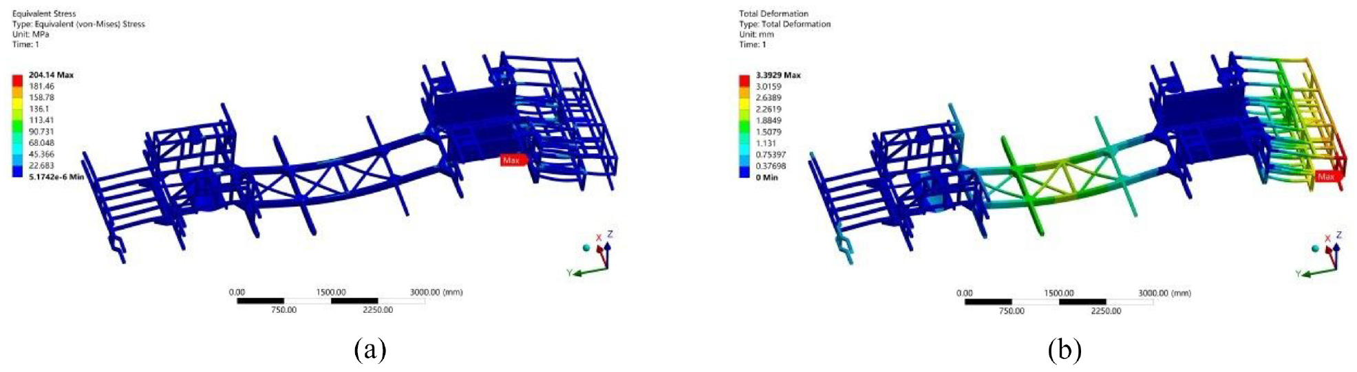
Finite element analysis results of the optimized frame under emergency braking conditions: (a) displacement nephogram; (b) stress nephogram.
It can be seen from the Figure 25 that the maximum stress value of the optimized frame under emergency braking conditions is 204.14 MPa, less than the allowable stress of the material 355 MPa, which decreases compared with the maximum stress value of the original frame, and the maximum stress point still appears on the support of the battery box group. The maximum displacement of the frame is 3.39 mm, and the maximum displacement point appears at the rear end of the frame.
The statics analysis results of the frame after topology optimization under emergency turning conditions are shown in Figure 26.
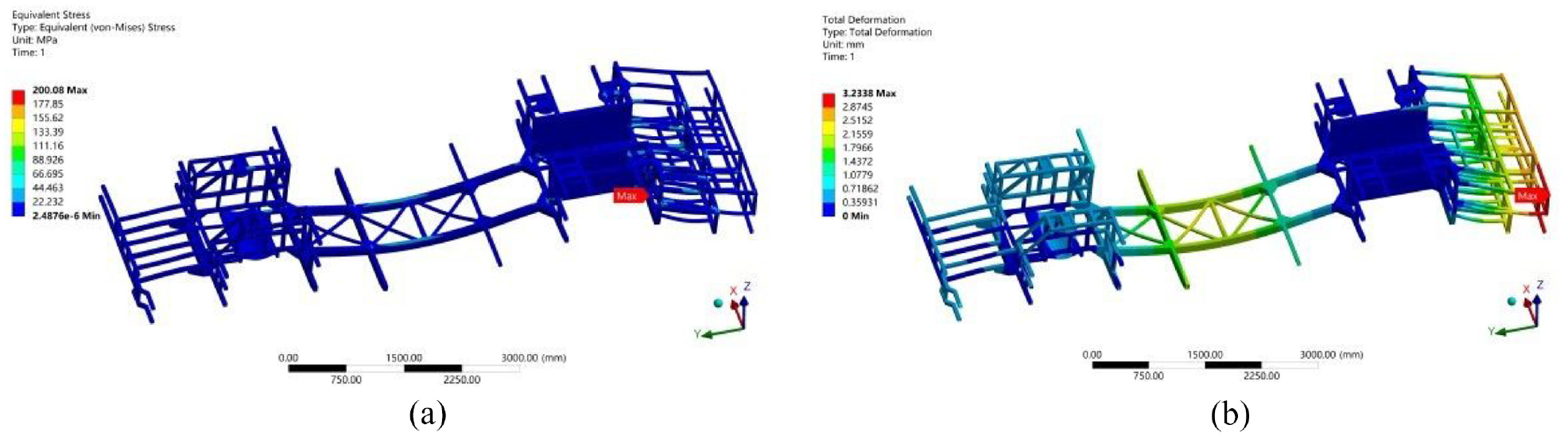
Finite element analysis results of the optimized frame under emergency turning conditions: (a) displacement nephogram; (b) stress nephogram.
As can be seen from the Figure 26, the maximum stress value of the optimized frame under emergency turning conditions is 200.08 MPa, which is less than the allowable stress of the material, 355 MPa. Compared with the maximum stress value of the original frame, the maximum stress point still appears on the support of the battery box group. The maximum displacement of the frame is 3.23 mm, and the maximum displacement point appears at the rear end of the frame.
The overall performance of the frame before and after topology optimization is shown in Table 8. From the table, it can be seen that the mass of the topology-optimized frame is 1129.20 kg, which is 16.5 kg (1.4%) less compared to the original frame. From the data, except for the torsion condition, the new frame structure performs better in terms of bending, braking, and cornering conditions compared to the original frame. Although the maximum displacement under torsion conditions is slightly higher in the new frame, the maximum stress value is lower than that of the original frame. The structural optimization design of the frame further enhances its overall structural performance.
Comparison of the frame performance before and after optimization.

Conclusion
This paper proposes a multi-objective topology optimization design process that integrates the Analytic Hierarchy Process (AHP), providing a theoretical basis for the topology optimization design of frames under complex operating conditions. The specific conclusions are as follows:
(1) A novel decision-making method for determining weight ratios in multi-objective optimization is proposed and innovatively applied to complex frame structures constructed from welded rectangular steel materials.
(2) From the results of the multi-objective optimization, the optimized frame outperforms the original frame. The frame’s weight is reduced by 16.5 kg, and the overall performance of the optimized frame has also shown significant improvement.
Therefore, through the AHP-based multi-objective topology optimization method, we can not only address the frame optimization problem but also overcome the limitations of traditional finite element analysis methods in comprehensively enhancing vehicle performance. This provides theoretical guidance and practical engineering reference value for the multi-objective topology optimization of more complex welded structural engineering. Future research can apply the proposed method to actual vehicle production to verify its superiority.
Footnotes
Handling Editor: Aarthy Esakkiappan
Declaration of conflicting interests
The author(s) declared no potential conflicts of interest with respect to the research, authorship, and/or publication of this article.
Funding
The author(s) received no financial support for the research, authorship, and/or publication of this article.