
Abstract
The hot blast stove is an important facility in the steel industry, which of the expansion gaps design has a significant buffering effect on the thermal stress with a high-temperature operating process. In this paper, a 3D numerical model of a hot blast stove was established to calculate the thermal stress distribution and analyze the remaining thickness of expansion gaps with different parts during the operating process. Young’s Modulus of the refractory linings was obtained by comparing with the experiment data and numerical data under the different temperatures and considering the influence of mortar. The result shows that Young’s Modulus of the refractory brick increased as the temperature, and the comparison of the experiment and simulation data of Young’s Modulus under three different temperatures displayed good agreement between the two sets of data. The first/third principle stress for the refractory linings can be reduced effectively by designing the expansion gap rationally, and the equivalent stresses of the shell are mainly concentrated at the joint and the neck. In addition, the expansion gaps are decreased under the thermal expansion and moved along a radial direction for the combustion/checker dome and the combustion/checker chamber.
Introduction
The cyclic operating process of a hot blast stove could be regarded as a quasi-steady state with high-temperature conditions, in which the structure and cycle process are complicated with a long operating cycle. 1 The structure of a hot blast stove could be damaged and collapse under expansion and compression during the operating process, and the hot blast stove cannot withstand the volume shrinkage that is caused by the huge temperature difference between opening and closing the hot blast stove. It means that the hot blast stove needs to maintain a high-temperature operating state until it is decommissioned. That will result in the design level of a hot blast stove directly affecting the service life. Therefore, how to achieve the high-efficient and long-lasting stable operation of a hot blast stove under the high-temperature conditions is currently the focus of the design. At present, the design method of hot blast stoves is generally used to absorb the thermal expansion and buffer the effect of thermal stress by designing expansion gaps. To optimize the design of hot blast stoves on the next step, authors are conducted to study the distribution of thermal stress and strain of hot blast stoves under the effect of expansion gaps in this paper.
At present, researchers are devoted to improving the characteristics of hot blast stoves by analyzing the heat exchange and the thermal stress with different boundary conditions. Such as Tomas Andres Flen et al. 2 studied the characteristics of a hot blast stove of the thermal dynamic heating cycle. Zetterholm et al.3,4 calculated the heat transfer efficiency and evaluated the performance of a hot blast stove during the operating process. Kimura et al. 5 analyzed the transient heat transfer in a hot blast stove and compared it with the measured data by considering the heat exchange between fluid and brick. Zhang et al. 6 analyzed the characteristics of a traditional top combustion hot blast stove. Xiao et al. 7 found that the guide vane angle was effective for the temperature distribution of the air distribution pipe, but hardly for the internal temperature field. Zhao et al.8,9 predicted flow, temperature, and concentration fields in the dome combustion chamber of the hot blast stove during an on-gas period and optimized the operation conditions. Yang et al. 10 designed an intelligent combustion control system to obtain good control performance in the absence of flow meters.
A few of researchers tried to improve the life of stoves by researching the thermal stress distribution and the refractory materials design. Such as Gan et al. 11 analyzed the maximum/minimum principal stress of the refractory linings and shell based on the result of the thermal analysis. Yan and Cheng 12 discussed the thermal stresses and deformations of the shell and piping system. Hwang and Lee 13 designed the layout of the refractory bricks and the space width between the insulation bricks for hot blast stoves. Hassleman 14 analyzed the problem of material selection involving thermal stress fracture and crack propagation in the engineering design period. Gruber et al. 15 studied the effectiveness of material parameters of the refractory materials on the life of the furnace.
To the author’s knowledge, the research of the heat transfer and flow rate for the hot blast stove has been relatively mature but the thermal stress analysis of the refractory linings and shell for the hot blast stove during the operating process is limited. Especially the research on the effect of expansion gap on the stress distribution of hot blast stoves has not been reported. This gap in the research motivated the authors to proceed with this investigation by using the thermal-structure coupling model and experimental to calculate the thermal stress distributions of a hot blast stove during the cyclic operating process under the action of an expansion gap. These results are used to analyze the stress concentration point and the distribution characteristics of the deformation by the effective expansion gap. It provides theoretical support to improve the structural stability and life of hot blast stoves.
Mathematical analysis
In this work, a hot blast stove is simulated via thermomechanical stress analysis by using a 3D numerical model and testing the mechanical performance of the refractory bricks to calculate the thermal stress and deformation distribution. The structure of the hot blast stove is mainly comprised of checker/combustion chamber, checker/combustion dome, cross-over, and cold flue/hot blast branch. The external structure of the hot blast stove mainly contains refractory linings and shell as shown in Figure 1. The structure of the refractory linings is complicated, and is comprised of staggered arrangements with many kinds of refractory brick and the insulting board, and two layers of refractory brick are connected by the mortar. Moreover, the expansion gap was designed in each part of the hot blast stove to absorb the thermal stress and strain, which is mainly comprised of the soft material of insulting board and polystyrene, where, the polystyrene in the expansion gap is melted with heating under the high-temperature conditions during the cyclic operating process.
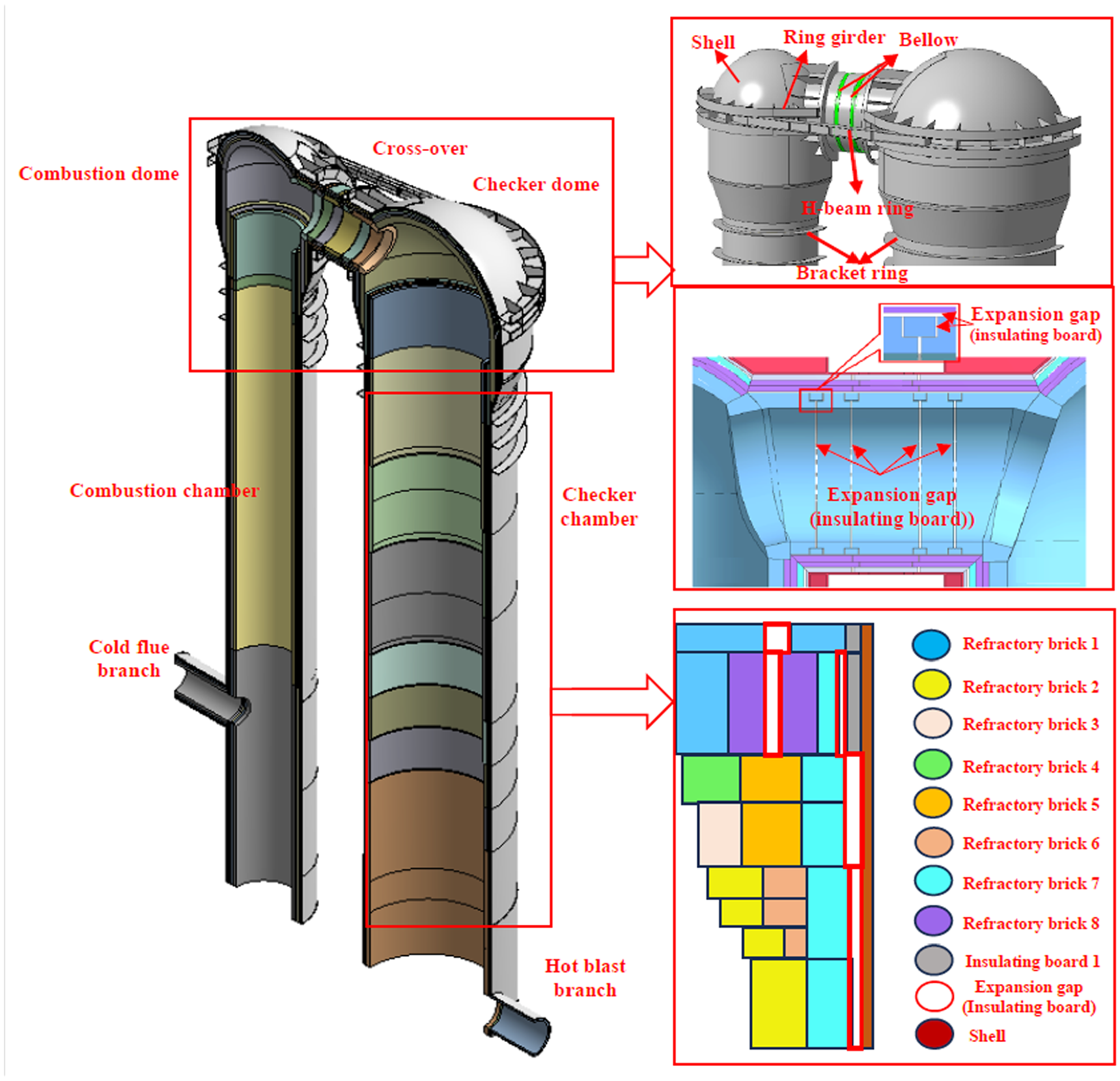
The physical model of the hot blast stove.
To ensure the strength of the hot blast stove, the bracket ring is designed at the neck between the combustion/checker dome and the combustion/checker chamber to disperse the gravity of the hot blast stove. The weight of the combustion/checker dome is carried by the bracket ring and then supported by the shell. In addition, the ring girder and H-beam ring are designed to restrain and connect the two sides of the shell, respectively. Meanwhile, two bellows are designed in the middle of the cross-over to improve the stability of the shell for the hot blast stove.
The expansion gaps are designed at the cross-over with a complex distribution to ensure the strength of the cross-over. Especially for the first layer of refractory brick, four expansion gaps are located on the inner surface, eight expansion gaps are located on the outer surface, and the gaps are connected by four horizontal expansion gaps. The other layer’s expansion gaps are located with staggered arrangements, too. The expansion gaps of the combustion and checker dome are designed similarly with different diameters. It is worth noticing that the structure of the checker chamber is more complicated than the combustion chamber due to the difference in the temperature distribution. The temperature of the combustion chamber hardly varied with the location but the checker chamber increased with the height due to the checker chamber being the main function to exchange the heat between the fluid and the checker.
Governing equations
For the three-dimensional temperature field analysis of the hot blast stove, it is assumed that all operation cycles are operated at a quasi-steady state due to the temperature difference of the hot blast stove between operation cycles can be ignored. Therefore, the temperature distribution of the refractory linings and shell are calculated with the steady state in this paper, and the energy equation 16 can be written as follows:
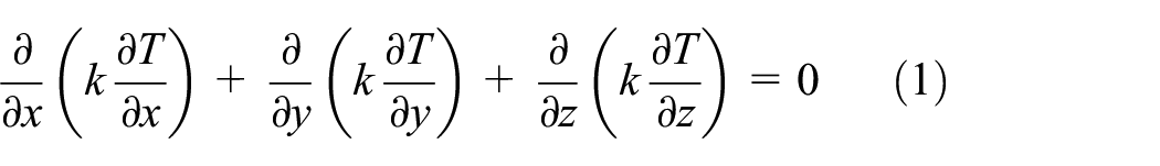
Where, k is the thermal conductivity and varies with temperature.
The mechanical strain and thermal strain are contained for the thermal stress numerical analysis of the hot blast stove:

Where,
The stress-strain and the shear-strain equations as follows:


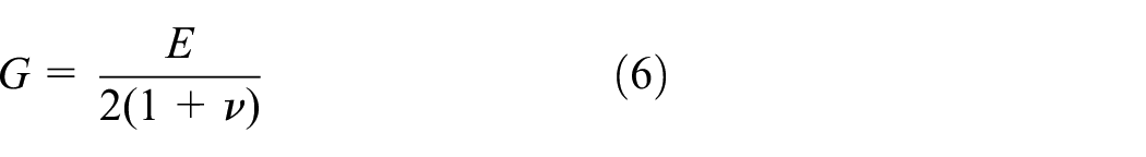
Where, E is Young’s modulus and obtained by experiment with different conditions,
The equation of static equilibrium can be written as follows:


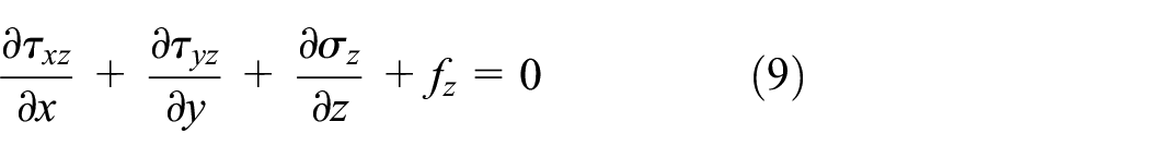
Where,
The principal stress is usually used to analyze the brittle material, such as the refractory linings. The tensile stress and the compressive stress of the refractory linings can be described as the maximum and minimum principal stress, respectively, which are estimated as the damage of brittle materials, and the equations can be displayed as follows:
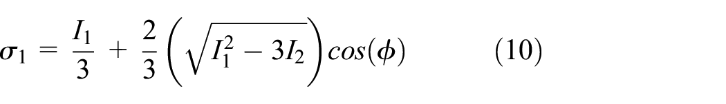

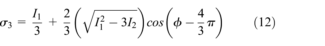
Where,


The equivalent stress is usually used to analyze the ductility material, and the Von-Mises criterion in this study is used to calculate the equivalent stress of the shell. The equations can be described as follows:


Material property
In this paper, all material properties are assumed homogenous and isotropic. Considering the influence of mortar between refractory layers on stress distribution, the material properties of refractory bricks coated mortar are the parameters of the refractory bricks in this paper. The properties of refractory linings and insulating boards are listed in Table 1. 17 Where the density, coefficient of thermal expansion, and Poisson’s ratio are used as the constant value, and the thermal conductivity is varied with the temperature.17–21
The material property of the refractory linings and insulating board.

To ensure the accuracy of the research, the Young’s Modulus of the refractory linings is obtained by comparing with the experiment data and numerical data under the different temperatures in this paper, and the test equipment, the test samples, and the simulation model are shown in Figure 2. Where, the mortar is located between two layers of refractory linings, and the property is between the fluid and solid, which is hard to obtain. It would affect the result of the numerical. The Young’s Modulus of the refractory brick-coated mortar with four kinds of arrangement of case 1, case 2, case 3, and case 4 are tested and compared with the numerical data under the different temperatures to solve this problem as shown in Table 2.
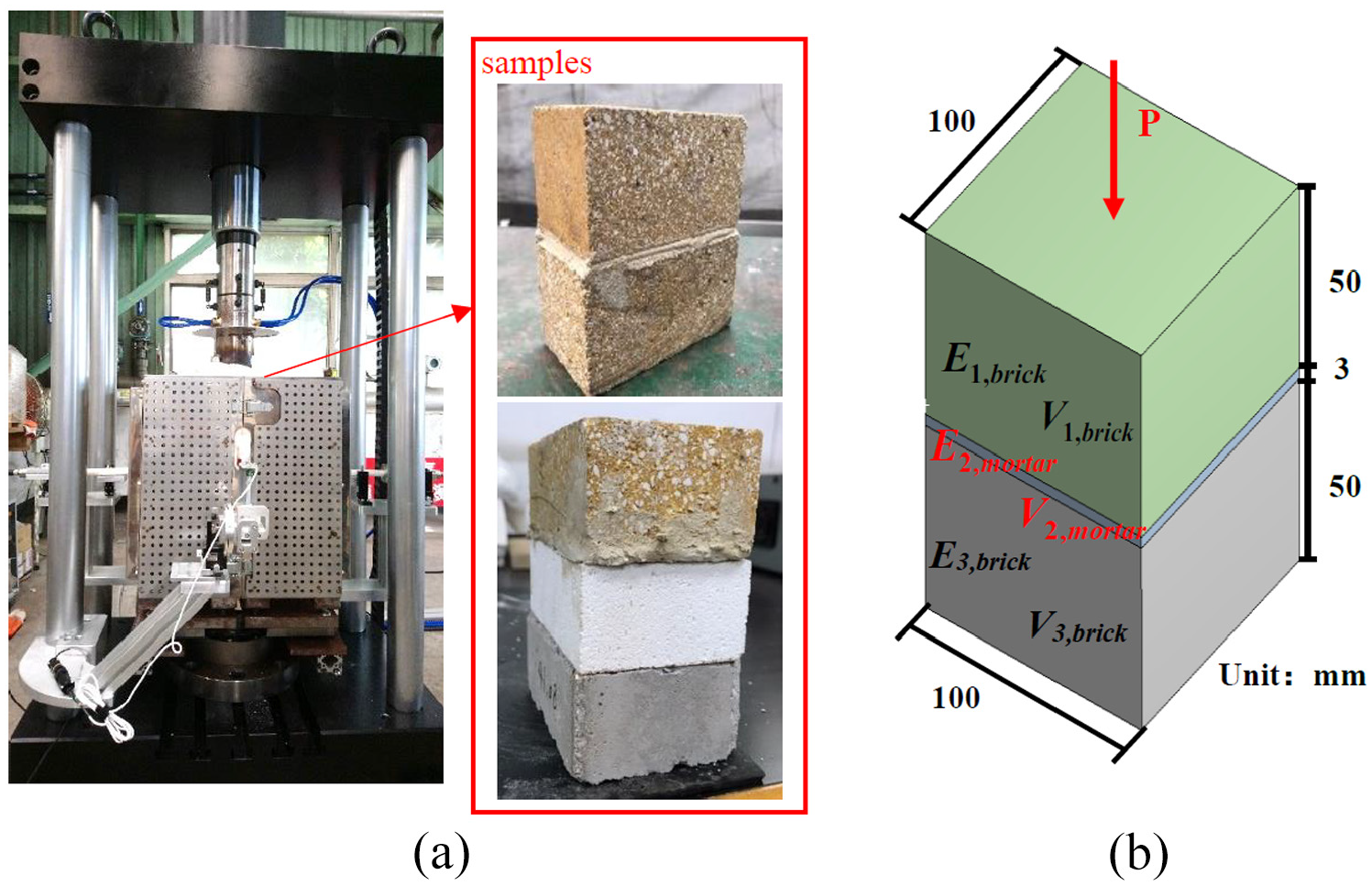
The (a) test equipment and (b) simulation model of the refractory bricks.
The case of the experiment.

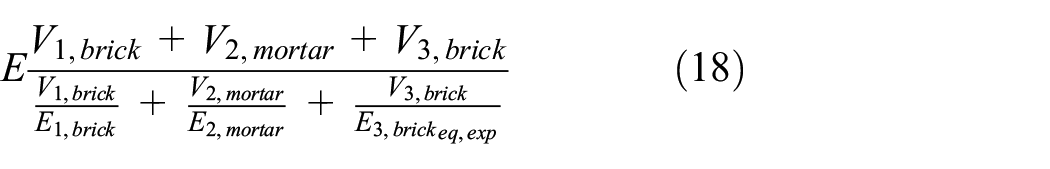
Figures 3 and 4 show the stress-strain result with the experiment of case 1 and case 2, respectively. It can be seen that Young’s Modulus increased as the temperature for the two cases, and the value of case 2 is lower than case 1, which of the values under the temperatures of 25°C, 300°C, and 500°C are 2.00, 2.25, and 2.40 GPa for case 1, and 1.60, 1.75, and 1.84 GPa for case 2, respectively. On the one hand, it indicates that Young’s Modulus of the refractory brick is decreased under the multilayer arrangement condition due to some certain tensile stress eliminated by mortar. Therefore, the influence of the mortar between the refractory bricks is considered in this study. On the other hand, Young’s Modulus of mortar can be estimated with the equivalent equation under the experiment data of case 1 and case 2, which of the values under the temperatures of 25°C, 300°C, and 500°C are 0.209, 0.208, and 0.210 GPa, respectively. Based on the calculation data of mortar, the Young’s Modulus of mortar for case 2 is calculated in reverse by the equivalent equation, and the error is lower than 7% by comparing with the experiment data as shown in Table 3. The equivalent of Young’s Modulus of refractory linings and error can be calculated as follows,

The experiment data of Young’s Modulus for the case 1.

The experiment data of Young’s Modulus for the case 2.
Comparison of the experiment and simulation data of Young’s Modulus for case 1 and case 2.

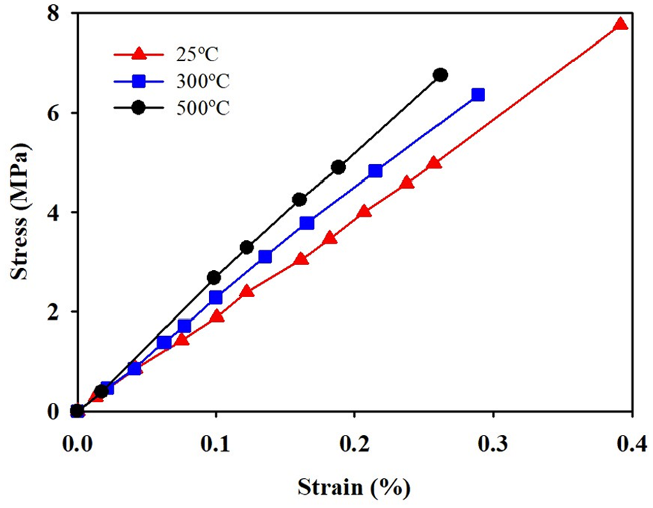
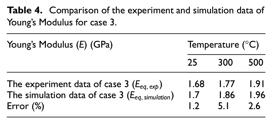
Meanwhile, the comparison of the experimental and numerical data of case 3 is shown in Figure 5 and Table 4 to ensure the accuracy of the equivalent Young’ Modulus equation. The stress-strain results show that the numerical data are almost consistent with the experimental data under the temperatures of 25°C, 300°C, and 500°C with errors of 1.2%, 5.1%, and 2.6%, and the experimental values are 1.68, 1.77, and 1.91 GPa, respectively. Moreover, the numerical data of case 4 by using the equivalent Young’s Modulus equation to compare with the experimental data is shown in Table 5. The result displays that, even for the three layers of heterogeneous refractory linings, the numerical data are mutually consistent with the experimental data under the temperature, which of the errors of 25°C, 300°C, and 500°C are only 6.4%, 1.1%, and 8.3%, respectively. In addition, the experimental data of the Young’s Modulus under the temperatures of 25°C, 300°C, and 500°C are 0.76, 0.84, and 0.82 GPa for case 4, respectively, which are lower than the value of the case 1, case 2, and case 3.

The comparison of the experimental and numerical data of case 3.
Comparison of the experiment and simulation data of Young’s Modulus for case 3.
Comparison of the experiment and simulation data of Young’s Modulus for case 4.

Boundary conditions
The thermal stress and deformation are formed by the nonuniformity temperature distribution. For temperature analysis of the hot blast stove, the temperature boundary condition is shown in Figure 6. Where the inner surface temperature distribution of the refractory linings is quoted with the thermo-hydraulic simulation result of the author’s earlier research at the quasi-steady state, 11 and the convective heat transfer between the outer surface of the shell and the environment is evaluated by using the equation:

Where, h is the convective heat transfer coefficient for the surface of the shell,
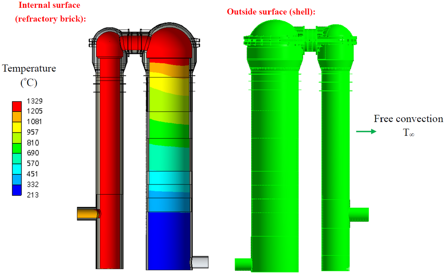
The temperature boundary condition of the hot blast stove.
For the stress-strain analysis of the hot blast stove, the stress boundary condition and constraint condition are shown in Figure 7. It can be described that the fixed support is set at the bottom of the combustion chamber and checker chamber for the hot blast stove and considered the gravity in the meantime. The inner/outside surface of the refractory linings and the inner surface of the shell are set at a pressure of 0.4 MPa by considering the operating mode conditions. The cold/hot branch of the shell and the bellows of the cross-over are set as the spring constant, and the value is shown in Table 6. In addition, due to the mortar hardly withstand the shear stress, it is assumed that the parallel contact surfaces between different refractory bricks can be moved with slip.

The stress boundary condition and constraint condition of the hot blast stove.
Spring constant.

Numerical method
In this study, the commercial software ANSYS is adopted to solve the governing equations, the finite element method is used to simulate the stress and strain field. The computational grids for the three-dimensional models are 1,390,000 cells for thermomechanical stress analysis. The hexahedron mesh and tetrahedral mesh are used in the model with flexible size to improve the calculation accuracy as shown in Figure 8. 22 However, a careful check of the grid independence of numerical solutions was made to ensure the accuracy and validity of numerical results. For this purpose, the symmetry model grid systems were tested, which comprised 1,130,000 and 1,540,000 cells for temperature and thermal stress analysis. It can be found that the relative errors under the same conditions among the temperature and stress solutions obtained with three types of grids were less than 5%. The discretized system was solved iteratively until it satisfied the following residual convergence criterion. The flowchart of the calculation process is plotted in Figure 9.

Where,

Computational grid system.

The flowchart of the calculation process.
Result and discussion
To ensure the validity of the simulation results, the temperatures of the inner surface are obtained by the thermo-hydraulic simulation, 11 which of the temperature distribution is already compared with the corresponding in situ data at three points with the maximum error lower than 7%. The temperature distribution of the refractory linings and shell are calculated by the given temperature of the inner surface and the boundary condition of the outer surface in this study as shown in Figure 10. The inner surface temperature of the shell by numerical analysis with point 1 and point 2 are compared with the corresponding in situ data. The result displays that the temperature at point 1 and point 2 are all 99°C for the numerical data, and the temperature at point 1 and point 2 are 98°C and 97°C for in situ data, respectively. It can be seen that the two sets of data have good consistency, and the maximum error is lower than 2% between the numerical data and in situ data.
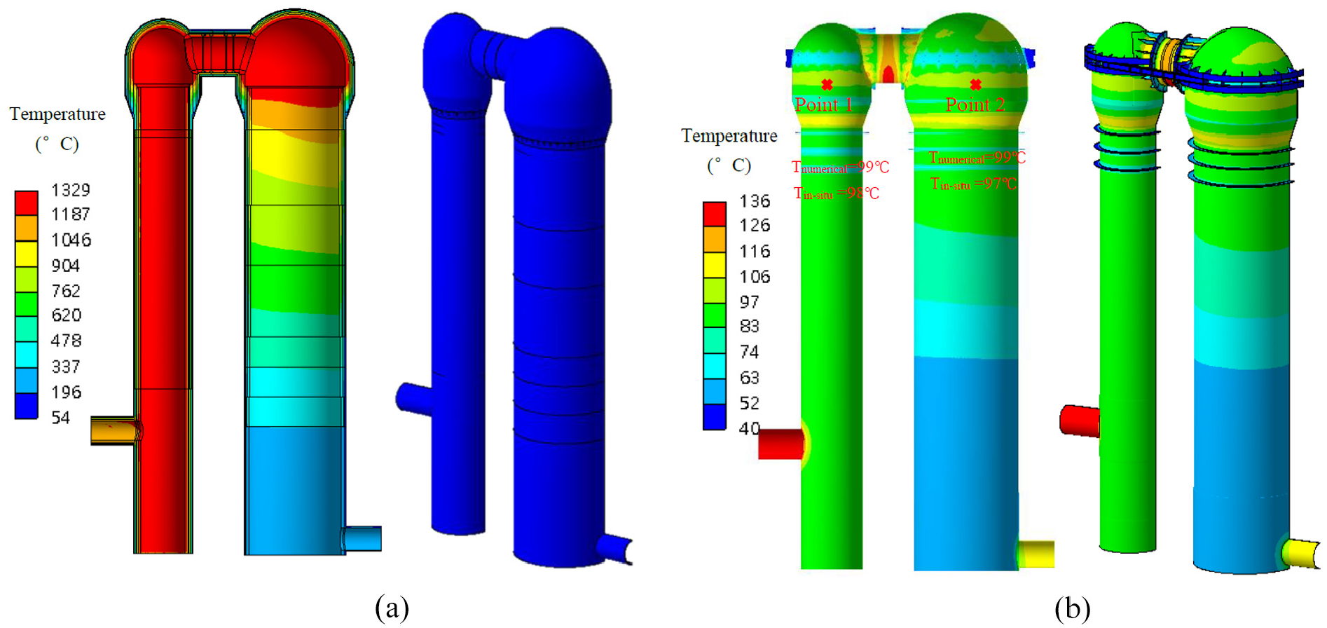
The temperature distribution of the refractory linings and shell: (a) the temperature contour of the refractory brick and (b) the temperature contour of the shell.
Figure 11 illustrates the deformation distribution for the refractory linings of the hot blast stove. Figure 11(a) displays that the deformations of the combustion/checker dome are independent of the combustion/checker chamber. It is can be explained that the structure of the combustion/checker dome is directly supported by the bracket ring on the shell, but not by the combustion/checker chamber. Therefore, the displacement of the combustion/checker dome was not based on the position of the chamber, but on the position of the bracket ring on the shell. Apparently, the maximum total deformation occurred at the top of the combustion chamber bot and the checker chamber but not at the combustion/checker dome with the values of 241 and 111 mm, respectively, which was slightly larger than the result of the refer 11 by considering expansion gap. Figure 11(b) shows that the direction of the deformation is generally upward and outward, and the Y-direction of deformation distribution is mutually consistent overall with the total direction of deformation, which is shown in Figure 11(c). It can be found that the expansion gap provides space for the heat expansion of the refractory linings.
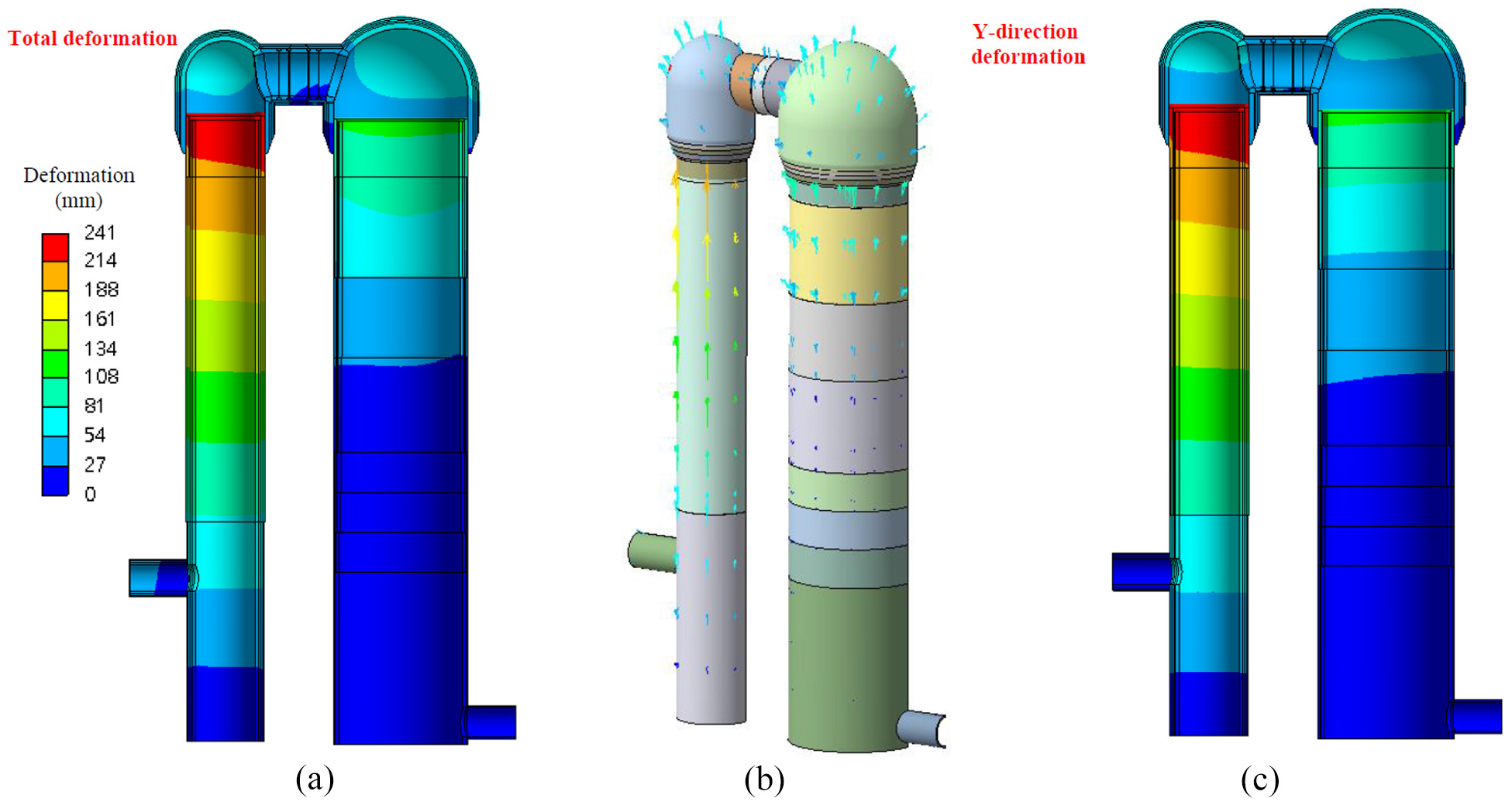
The deformation distribution of the refractory brick: (a) the total deformation, (b) the vector of the total deformation, and (c) the Y-direction of deformation.
Figure 12 shows the first principle stress contour for the refractory linings of the hot blast stove. By comparing Figure 12(a) and (b), it can be found that the first principle stress as the tensile stress occurred mainly at the outside of the refractory linings for the hot blast stove, which of the distribution is similar to the result without expansion gap. It needs to be noticed that the value of the first principal stress is obviously lower than the result of the refer 11 by considering the expansion gap in this study. Especially for the chamber/combustion dome, the cross-over, and the neck (the junction of the dome and chamber), the maximum value of the first principal stress is only about 5 MPa. Meanwhile, the two layers of refractory bricks connected by mortar can be separated if it is subjected to greater tensile stress. It means that the mortar increases the tolerance of tensile stress for a hot blast stove. Therefore, it can be stated that the first principle stress for the refractory linings of the hot blast stove is in the safety range.

The first principle stress distribution of the refractory brick: (a) the first principle stress distribution with expansion gap and (b) the first principle stress distribution without expansion gap.
Figure 13 displays the third principle stress contour for the refractory linings of the hot blast stove. It can be observed that the compressive stress occurred mainly at the outside of the refractory linings from Figure 13(a) and (b). It is noted that, as the same as the first principle stress, the value of the stress is also apparently lower than the result of the refer 11 by considering the expansion gap. The maximum value of the third principal stress for the combustion chamber and the hot blast branch is within −15 MPa, which of the stress concentration phenomenon is also obviously improved by comparing without an expansion gap. It can be seen that both the first principle stress and the third principle stress for the refractory linings of the hot blast stove can be reduced effectively by rationally designing the expansion gap.
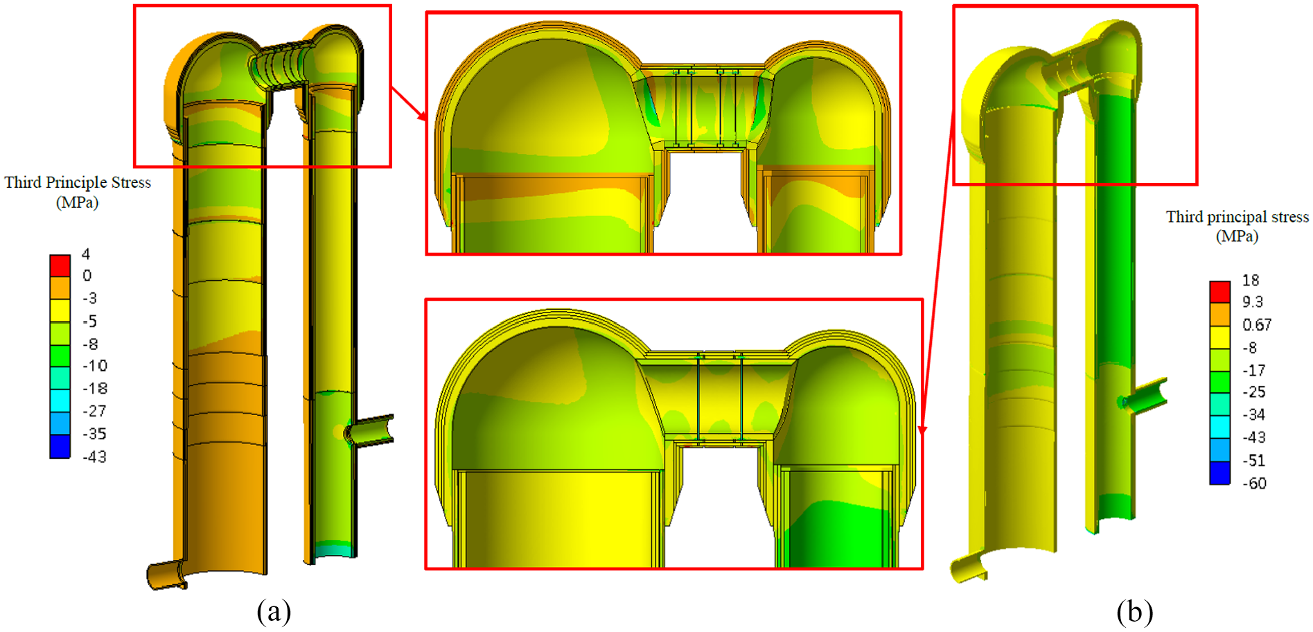
The third principle stress distribution of the refractory brick: (a) the third principle stress distribution with expansion gap and (b) the third principle stress distribution without expansion gap. 11
Figure 14 illustrates the deformation distribution of the shell for the hot blast stove to analyze the deformation state of the shell during the operating process. It can be observed that the deformation is continuous for the total shell, and the maximum total deformation of 37 and 32 mm occurred at the top of the combustion dome and the checker dome, respectively. The deformation value at the combustion dome is larger than checker dome as shown in Figure 14(a). It is explained that the design height difference existed between the combustion dome and the checker dome, which is used to balance the different deformation during the operating process. The direction of the deformation is mainly upward with slight outward due to the shell being constrained and connected by the ring girder and the H-beam girder as shown in Figure 14(b). Therefore, the Y-direction of deformation distribution is almost consistent with the total direction deformation, which is shown in Figure 14(c).

The deformation distribution of the shell: (a) the total deformation, (b) the vector of the total deformation, and (c) the Y-direction of deformation.
Figure 15 displays the Von-Mises equivalent stress distribution of the shell for the hot blast stove to describe the state of stress for the shell. During the operating process, the pressure of the gas in the hot blast stove is acted on the iron shell, and the direction is perpendicular to the surface. It means that the joints between the combustion/checker dome and the neck are pressured in two directions, which results in the equivalent stresses being concentrated at the joints (such as stress concentration position 1) with the maximum value of 311 and 284 MPa, respectively. In addition, the bracket ring at the necks between the combustion/checker chamber and the combustion/checker dome is in direct contact with the shell and without an expansion gap. It means that the equivalent stresses are also concentrated at the necks (such as stress concentration position 2) with the maximum value of 305 and 202 MPa, respectively. However, for the other part of the shell, the equivalent stresses are lower than 100 MPa except for the bottom of the shell, which is set as a fixed support condition. It can be seen that was not enough to damage the shell despite the presence of stress concentration spots.

The Von-Mises equivalent stress of the shell.
Figure 16 shows the main variation of the expansion gap for the combustion chamber and checker chamber after thermal expansion. For the combustion chamber, the high temperature is distributed uniformly with the entire combustion chamber during the operating process, which results in the expansion gap decreasing and moving radially as shown in Figure 16(a). It can be seen that the expansion value is about 20 mm through the entire combustion chamber with the remaining thickness of 5–6 mm along the height. In addition, the temperature of the checker chamber is increased as the height, which the range is 213°C–1323°C. It means that the expansion mainly occurred at the upper of the checker chamber, and the expansion gap is decreased and moved radially similar to the combustion chamber as shown in Figure 16(b). However, due to the diameter of the checker chamber being larger than the combustion chamber, the expansion value radially at the upper of the checker chamber is larger than the combustion, which of the remaining thickness is only 0.1–4.1 mm.

The variation of the expansion gap for the (a) combustion chamber and (b) checker chamber.
Figure 17 indicates the variation of the expansion gap for the combustion dome and checker dome after thermal expansion. The expansion phenomenon of the combustion dome and checker dome are similar to each other, and the expansion values are described with three lines with different colors along the x-direction as shown in Figure 17(a) and (b), respectively. Where, the black line, blue line, and green line are displayed in the spherical region of the dome, the vertical region on the outside of the dome, and the joint region with the chamber, respectively. It was obvious that the remaining thickness at the middle is lower than the left and right ends along the x-direction, and the expansion value with the black line is larger than the green line. It can be explained that the spherical region of the combustion and checker dome are connected with the cross-over resulting in a larger expansion value with the minimum remaining thickness of 12 and 10 mm, respectively. However, the joint region of the combustion and checker dome is supported by the shell without an expansion gap, which results in both the combustion dome and checker dome expansion value at the end of the green line being 0 mm.

The variation of the expansion gap for the combustion dome and checker dome: (a) the expansion of combustion dome and (b) the expansion of checker dome.
Figure 18 illustrates the variation of the expansion gap for the cross-over along the radial and axial direction. Due to the thermal expansion of the cross-over being moved upward during the operating process, the design expansion gap along the radial direction is gradually increased from the bottom to the top, which of the value are 3 and 40 mm for the bottom and the top of the cross-over, respectively. In order to describe the deformation of the cross-over along the radial direction more clearly, the remaining thickness along the axial direction at the top of the cross-over is drawn in Figure 18(a), in which the range is about 22–32 mm. It can be found that four expansion gaps are located at the cross-over along the axial direction, and the two of the expansion gaps near the combustion dome and the other two gaps near the checker dome are 30 and 40 mm, respectively. The expansion gap decreased and moved in two directions as shown in Figure 18(b) and (c), in which the range of the remaining thickness are 20–26 and 20–27 mm after expansion, respectively. In addition, the remaining thickness of the two expansion gaps in the middle is slightly lower than that of the two expansion gaps on both sides due to the two sides of the cross-over are restricted by the combustion and checker dome. In order to ensure the safety of the cross-over, the safe value of the remaining thickness is set at the expansion gaps, and the result shows that all of the remaining thicknesses are larger than the safe value. That means that the design of the expansion gap is enough to support the thermal expansion of the hot blast stove.
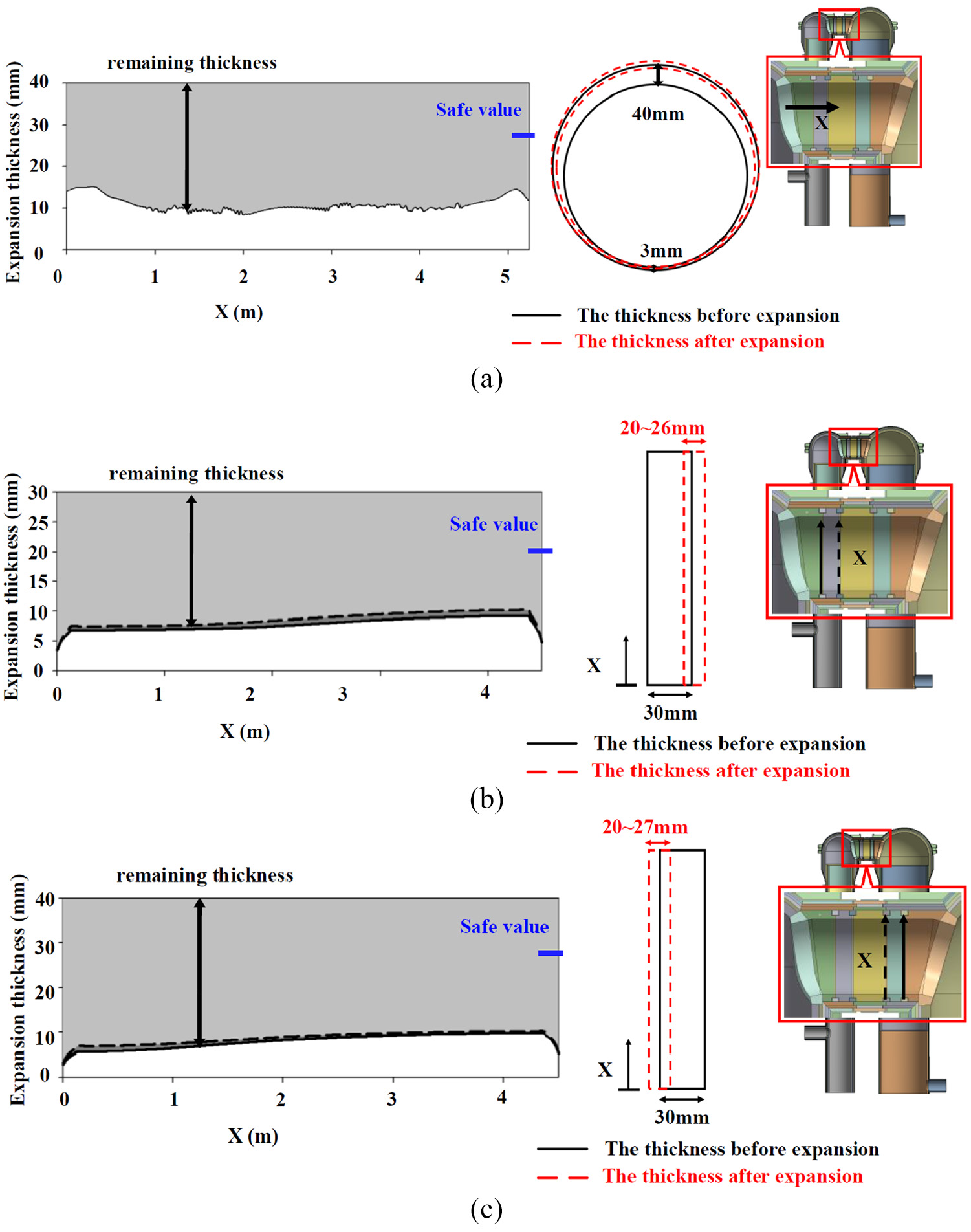
The variation of the expansion gap for the cross-over: (a) the radial expansion of the cross-over, (b) the axial expansion of the cross-over nearby the combustion dome, and (c) the axial expansion of the cross-over nearby the checker dome.
Conclusion
In this paper, two points of simulation temperature for the shell are compared with the in situ data, and the Young’s Modulus of the refractory linings are obtained by comparing with the experiment data and numerical data under the different temperatures to calculate the temperature and thermal stress distribution by building a 3D simulation model of a hot blast stove. Moreover, the thermal stress and deformation distribution of the refractory linings and the shell of the hot blast stove are calculated by considering the expansion gap. Based on the numerical results, the conclusion can be summarized as follows:
The Young’s Modulus of refractory brick increased as the temperature, and can be decreased by adding the coating mortar.
A comparison of the experiment and simulation data of Young’s Modulus under three different temperatures are mutually consistent overall.
The inner surface temperature of the shell was verified by the corresponding in situ data.
The deformation of combustion/checker dome is independent of the combustion/checker chamber due to the dome of the hot blast stove supported by the bracket ring on the shell. The maximum total deformation occurred at the top of the combustion chamber and the checker chamber slightly larger than the result without considering the expansion gap.
Both the first principle stress and the third principle stress for the refractory linings of the hot blast stove can be reduced effectively by designing the expansion gap rationally. The equivalent stress for the shell is mainly concentrated at the joints between the combustion/checker dome and the neck, and the value is not enough to damage the shell despite the presence of stress concentration spots.
The expansion gap of the hot blast stove is decreased under the thermal expansion, which is moved outward and upward along the axial direction and radial direction during the operating process, respectively. Moreover, the joint region between the neck and the combustion/checker chamber is supported directly by the shell without expansion gap. All of the remaining thicknesses for the cross-over are larger than the safe value. Therefore, the design of the expansion gap is enough to support the thermal expansion of the hot blast stove.
Footnotes
Acknowledgements
The authors are grateful to Pro. Jiin-Yuh Jang of National Cheng Kung University, Taiwan, for his valuable guidance.
Handling Editor: Aarthy Esakkiappan
Declaration of conflicting interests
The author(s) declared no potential conflicts of interest with respect to the research, authorship, and/or publication of this article.
Funding
The author(s) disclosed receipt of the following financial support for the research, authorship, and/or publication of this article: Financial supported for this work was provided Jiangxi University of Science and Technology, Ganzhou, under Contact No. 205200100495, and the Science and Technology of Jiangxi Provincial Department of Education, Ganzhou, under Contact No. GJJ210813.