
Abstract
Ionic Polymer Metal Composite (IPMC) can be used as flexible actuators and sensors in the fields of bionic machinery and medical devices. However, IPMC still suffer from poor actuation performance and high cost of electrode preparation in practical applications. Optimisation of electrodes and use of novel assembly processes are expected to solve these problems. In this paper, low-dimensional nanocarbon materials were used to modify the Nafion membrane. Appropriate amounts of carbon nanotubes and carbon black were weighed and dispersed in chitosan and acetic acid to form a stable electrolyte. A new IPMC was prepared by bonding carbon nanotube and carbon black films on the Nafion membrane using the hot pressing method. Scanning electron microscope images showed that the hybrid films composed of carbon nanotubes and carbon black were successfully hot pressed onto the surface of the Nafion membrane and the hybrid electrode layer composed of carbon nanotubes and carbon black was more homogeneous and densely packed. The results of driving performance tests show that the hybrid electrode-modified IPMC has excellent driving performance, with a maximum output displacement of 9.2 mm and a maximum output force of 9.9 mN at a voltage of 5.0 V. These results are 1.07 and 1.14 times higher than those of the carbon nanotube IPMC and 1.74 and 1.70 times higher than those of the carbon black IPMC under the same conditions, respectively.
Introduction
Ionic polymer metal composites, also known as artificial muscle materials, is a highly interdisciplinary research field that overlaps with and has good application prospects in the fields of materials science, chemical engineering, mechanical engineering, electrical engineering, etc. 1 IPMCs can produce bending in excess of 90° under low voltage actuation (less than 10 V), and have the advantages of fast response time, small strain deformation and long service life.2–4
When a human muscle does work, it generates tension. The magnitude of this tension depends on the size of the physiological cross-section of the muscle, the degree of neuromuscular excitation and the length of the muscle. The length of the muscle determines the maximum distance that the muscle can be shortened while working (Figure 1(a)). Artificial muscles mainly consist of an ion exchange membrane and metal flexible electrodes on both sides.5,6 Hydrated cations within the ion exchange membrane under external voltage excitation carry solvent molecules towards the cathode through tiny tubes within the membrane. This leads to a decrease in the water content of the anode and an increase in the water content of the cathode, so that a driving bending deformation occurs (Figure 1(b) and (c)).7,8

(a) Human muscle composition, (b) and (c) schematic diagram of artificial muscle.
Currently, the main challenges for ion-polymer-metal composite actuators are to achieve large electromechanical deformation, fast switching response, low operating voltage and long-lasting operation. 9 The chemical and mechanical stability of the electrodes is the basis for the IPMC to be able to work for a long time. The actuation and sensing of the IPMC rely on the electromechanical coupling between the electrodes and the ions, and the performance of the surface flexible electrodes plays a crucial role in the actuation and sensing performance of the IPMC.
The main electrode materials used in IPMC are metallic materials, conductive polymers and carbon materials. For example, He et al. 10 showed that the traditional Pt-IPMC driver only has a cycle life of about 5000 cycles, after which the surface metal electrodes will crack and oxidise off, and cracks will appear, which will lead to the rapid failure of the IPMC driver; Liang Yang et al. 11 prepared IPMCs with silver-copper hybrid electrodes by using ion reduction hybrid electroplating, in which the copper content was 89.94% and silver content of 8.52%, which improved the performance of IPMC. Although metal electrodes have better electrical conductivity, they also have the disadvantages of corrosion susceptibility, surface cracking6,12–14 and excessive rigidity. Chemically more active metal materials are prone to oxidation and corrosion, especially in the energised state will accelerate the rate of metal corrosion13,15; therefore, active metal materials usually can not be used as IPMC electrodes alone for a long period of time.
Commonly used conductive carbon materials mainly include carbon nanotubes, graphene and carbon black.16–18 Compared to metallic materials, carbon nanomaterials such as carbon nanotubes and graphene theoretically have excellent conductive properties and are less expensive. 19 Guan et al. 20 investigated an ion actuator based on graphite carbon nitride nanosheet electrodes, which showed high electrochemical activity and electromechanical conversion capability. It is characterised by large specific capacitance, fast drive response within 300 ms, large electromechanical strain, high drive and high stability. However, affected by the preparation conditions and processes, the prepared carbon IPMC actuators have problems such as the performance not reaching the theoretical performance and the long preparation cycle.
Many of the previous researches are mostly incorporating a conductive material in polymers,21,22 in this paper, we use chitosan and acetic acid solution to hot-press bonding of two carbon-based conductive materials. As shown in Figure 2, carbon black is a granular conductive agent and carbon nanotubes are hollow tubular conductive agents, and the combination of carbon black and carbon nanotubes can have a synergistic enhancement effect. Carbon nanotubes and carbon black after compounding can be microscopically similar to the formation of grapevine-like conductive structure, the organic combination of points and lines to form a three-dimensional conductive network, greatly improving the conductive capacity, the reinforcing effect has also been greatly enhanced. Carbon black (CB) and carbon nanotubes (CNTs) can be made into polymer conductive composites with good processing properties. Highly conductive carbon black is characterised by high structure, low resistance and easy dispersion. High structure carbon black, very low addition amount can achieve excellent conductivity. The conductivity is basically unaffected after secondary crushing. CNTs have many excellent properties and their great aspect ratio can make the composites have a low percolation threshold, but CNTs are not conducive to cost reduction because of their high price. The low-priced CB and CNTs with excellent performance can be mixed and filled to improve the comprehensive performance of the material and reduce the amount of each filler to achieve the purpose of improving the performance and reducing the cost.

Experimental principle of IPMC with composite electrodes.
Materials and method
The improvement of IPMC preparation process can enhance the performance of IPMC, reduce the production cost of IPMC and improve the production efficiency of IPMC. Figure 3 shows the flow chart of electrode preparation in this experiment.

Flow chart of electrode preparation.
Pre-treatment of membrane
Roughening of Nafion film surface: The surface of the Nafion film is polished to roughen the surface to facilitate the adhesion of the carbon material during hot pressing.
Preparation of carbon nanotube IPMC electrode
The CNTs and were ultrasonically pulverised for 30 min, and then ultrasonically dispersed for 30 min. The magnetic stirrer was turned on, and a 3% solution of glacial acetic acid was configured, and 20 mL was taken out and poured into a beaker with a capacity of 50 mL, and heated to 45°. Wash the magnetic stirrer with distilled water and put it into the beaker, weigh 0.08 g of chitosan with an analytical balance, gradually add it to the beaker and stir for 30 min. 30 min later, chitosan was basically dissolved in the glacial acetic acid solution, measure the dispersed multi-walled carbon nanotubes in aqueous dispersion of 15 mL, slowly pour it into the chitosan acetate solution, and continue to stir to make the multi-walled carbon nanotubes and chitosan mix evenly. When the volume of the mixed solution evaporated from 35 to 20 mL, the stirring was stopped. The mixed solution was ultrasonically dispersed for 30 min, and then dried into a film in a vacuum drying oven. It was combined with Nafion membrane to form a film by hot pressing method, and the edges were cut to obtain carbon nanotube-type IPMC actuator (CNT-IPMC) with the size of 25 mm × 5 mm.
Preparation of carbon black IPMC electrode
The CB was ultrasonically pulverised for 30 min, and then ultrasonically dispersed for 30 min. The magnetic stirrer was turned on, and a 3% solution of glacial acetic acid was configured, and 20 mL was taken out and poured into a beaker with a capacity of 50 mL, and heated to 45°. Wash the magnetic stirrer with distilled water and put it into the beaker, weigh 0.08 g of chitosan with an analytical balance, gradually add it to the beaker and stir for 30 min. 30 min later, chitosan was basically dissolved in the glacial acetic acid solution, measure 15 mL of the dispersed multi-walled carbon nanotubes in aqueous dispersion, slowly pour it into the chitosan acetate solution, and continue stirring to make the carbon black and chitosan mix evenly. When the volume of the mixed solution evaporated from 35 to 20 mL, the stirring was stopped. The mixed solution was ultrasonically dispersed for 30 min, and then put into a vacuum drying oven to dry into a film. It was combined with Nafion film to form a film by hot pressing method, and the edges were cut to obtain carbon black-type IPMC actuator (CB-IPMC) with the size of 25 mm × 5 mm.
Preparation of composite electrode IPMC
The CNTs and CB were ultrasonically pulverised for 30 min, and then ultrasonically dispersed for 30 min. The magnetic stirrer was turned on, and a 3% solution of glacial acetic acid was configured, 20 mL of which was taken out and poured into a beaker with a capacity of 50 mL, and heated to 45°. Wash the magnetic stirrer with distilled water and put it into the beaker, weigh 0.08 g of chitosan with an analytical balance, gradually add it to the beaker and stir for 30 min. 30 min later, chitosan was basically dissolved in the glacial acetic acid solution, measure the dispersed multi-walled carbon nanotubes and carbon black dispersion of 15 mL, slowly pour it into the chitosan acetic acid solution, and continue to stir to make the multi-walled carbon nanotubes and chitosan mixing homogeneous. When the volume of the mixed solution evaporated from 35 to 20 mL, the stirring was stopped. The mixed solution was ultrasonically dispersed for 30 min, and then dried in a vacuum drying oven to form a film. It was combined with Nafion membrane to form a film by hot pressing method, and the edges were cut to obtain a hybrid IPMC actuator (CNT-CB-IPMC) with a size of 25 mm × 5 mm.
Results and discussion
SEM analysis
The surface morphology and cross-section morphology of IPMC brakes were observed by SEM (Hitachi Regulus 8100) in which the cross-section morphology was prepared by cryogenic cold forging with liquid nitrogen. The surface micromorphology and cross-section morphology of IPMC were observed by SEM electron microscope scanning, which can observe the coating of the surface electrodes and whether they are uniform or not. The more uniform and dense the surface of IPMC is, the better its conductivity is. The less energy consumption on the electrode surface when a signal is introduced, the stronger the braking of the IPMC. Figure 4(a), (c) and (e) gives the surface microscopic morphology of the three IPMCs. From the figure, it can be seen that the carbon nanotubes and carbon black mixture can be successfully deposited onto the Nafion film by hot pressing method. The surface microscopic morphology of the hybrid electrode IPMC 4(a) is more uniform and dense compared to the carbon nanotube electrode 4(c) and carbon black electrode 4(e), which is also the reason for the lower resistance of the hybrid electrode IPMC. Figure 4(b), (d) and (f) show the cross sections brittlely broken by liquid nitrogen. The cross-sectional morphology given by SEM electron microscopy magnified 200 times shows that the hybrid electrode 4(b) doped with carbon nanotubes and carbon black cross each other, which increases the internal specific surface area, increases the internal specific capacitance, and improves the electrochemical performance. 4(f) is the carbon black electrode IPMC From the figure, it can be seen that the electrode layer is slightly warped and the combination with the Nafion film is not tight enough, which affects the performance of the IPMC brakes.
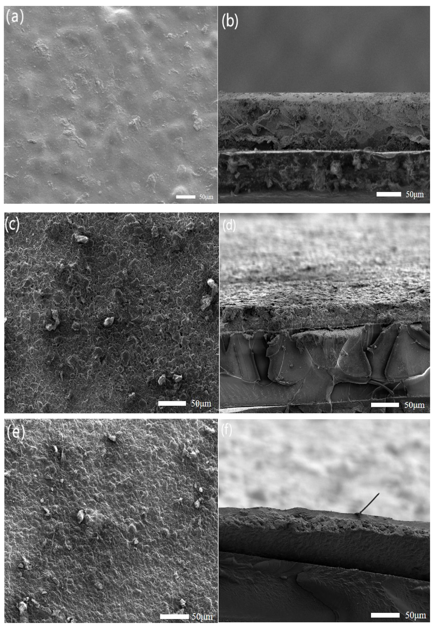
SEM images of CNT-CB-IPMC: (a) surface and (b) cross section; SEM images of CNT electrodes: (c) surface and (d) cross section; SEM images of CB electrodes: (e) surface and (f) cross-section.
Conductivity
When energised, the current decreases as current flows through the electrode layers. If the IPMC resistance is too high, it will result in too little current at the tip of the brake to measure an accurate value. The curvature of the IPMC also changes when energised, resulting in a non-linear change in resistance as well. The small value of the IPMC electrode resistance can be regarded as a measurement of the film resistance, that is, the square resistance. Therefore, in this paper, a precision multimeter (UNI-T, China) is used to measure the surface resistance of IPMC (the distance between the two probes is 1 cm, and the average value is taken after three measurements at different positions). As shown in Table 1.
Sheet resistance of the IPMC electrodes.

The resistance of IPMC using carbon black as electrode is high. The reason for this is the looseness of the electrodes made using the hot pressing method, the poor quality of the electrodes and the obvious gaps between the lamellae after deposition. For its own part, carbon black has lower conductivity than carbon nanotubes, so that makes its resistance the highest. And the resistance of the electrode using a mixture of carbon nanotubes and carbon black is lower because the combination of the two appears to have a fusion effect. It makes the surface of the electrode more uniform, and the hybrid electrode of carbon nanotubes and carbon black is more tightly bonded to the inner layer than the carbon black electrode, which improves the electrode performance of IPMC. The electrodes are less likely to fall off during testing, resulting in more stable displacement and force output.
CV analysis
The three IPMCs were scanned using an electrochemical workstation (CHI600 E, Shanghai Chenhua Instruments) at 0.5 and 1 V scanning intervals according to the scanning speeds of 0.1 v/s, 0.2 v/s and 0.5 mv/s. The voltammetric characteristic curves are shown in Figure 5, and from Figure 5(a) to (f), it can be seen that the curves are in a similar trend and the CV curves are smooth without interruptions and blurring. According to Figure 5(e) and (f) the CNT-CB type IPMC has a larger opening and higher specific capacitance, which forms a good bilayer effect and improves the specific capacitance of the IPMC. The reason is that the combination of carbon nanotubes and highly conductive carbon black in the hybrid electrode forms a conductive network to improve the conductivity of IPMC and reduce the surface resistance of IPMC. It is a great improvement over the normal single carbon material IPMC electrode, which can store more electrons. Figure 5(a) to (d). The IPMC voltammetric characteristic curves of the single carbon material are narrower, which indicates that the capacitor has a large internal resistance during charging and discharging, resulting in a larger consumption of its own electrical energy, which reduces its ability to hold electrons. It indicates that the specific capacitance is less and the reason for this aspect should be the loose IPMC electrodes prepared by hot pressing method. The narrowest IPMC voltammetric curve was found for the carbon black material, which is attributed to the fact that the carbon black material itself is less conductive than carbon nanotubes. In the test conducted on the single electrode of carbon black, the electrode had a small amount of detachment. And the bonding with the membrane is not tight enough, which is the reason for the poor performance of the carbon black electrode test.
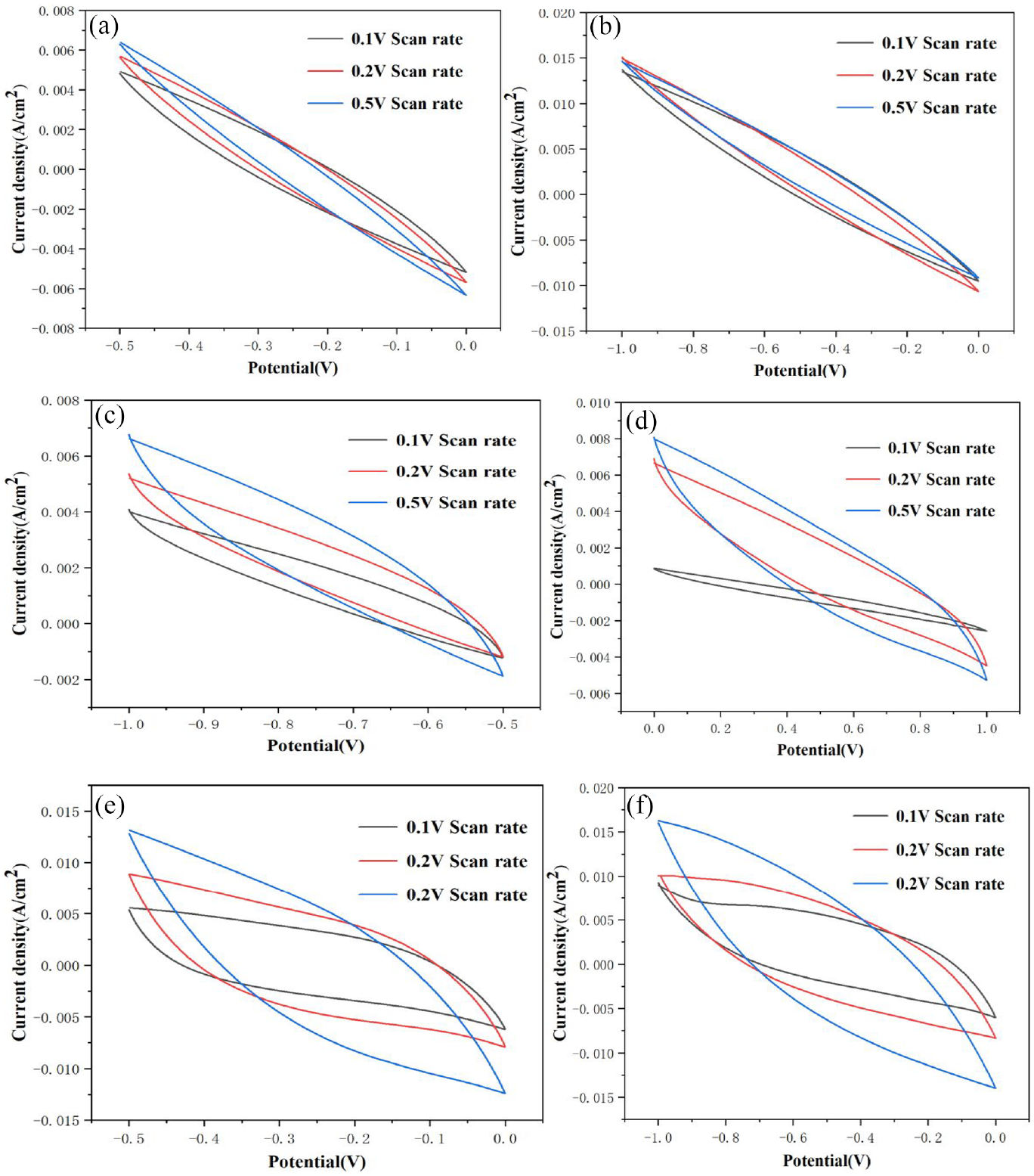
CV curves of CB electrodes: (a) 0.5 V scanning interval and (b) 1 V scanning interval; CV curves of CNT electrodes: (c) 0.5 V scanning interval and (d) 1 V scanning interval; CV curves for CNT-CB-IPMC: (e) 0.5 V scanning interval and (f) 1 V scanning interval.
Displacement output results and analysis
Output displacement is an important indicator of IPMC electric braking performance. In this paper, the displacements of CB-IPMC, CNT-IPMC and CNT-CB-IPMC actuators driven by 2.0, 3.0 and 5.0 V are tested respectively. The three carbon IPMCs were energised during the testing process, and the displacements of the three carbon IPMCs were measured with a displacement sensor, as shown in Table 2. From Table 2, it can be seen that the maximum output displacements of the three IPMC films increase as the driving voltage increases. Taking the CNT-CB-IPMC actuator as an example, the maximum displacements were 4.6, 5.0 and 9.2 mm at driving voltages of 2.0, 3.0 and 5.0 V. This indicates that the output displacements of the IPMC actuator are positively correlated with the driving voltage, and the output displacements increase with the increase of the voltage. For IPMCs with different electrodes, the output displacements of CNT-CB-IPMC are larger than those of CNT-IPMC and CB-IPMC under the same voltage drive (the maximum output displacements under the 5.0 V voltage drive are 8.6 mm and 5.3 mm, respectively). It is 1.07 and 1.74 times the maximum output displacement (number) of CNT-IPMC and CB-IPMC, respectively. The displacement under 5 V voltage is shown in Figure 6. It can be clearly seen that the displacement of Figure 6(c) CNT-CB-IPMC is obviously the largest, and the reason for the small displacement of Figure 6(a) and (b) is as follows: the increase in electrode surface resistance, the energy consumption of the electrode surface after energisation is large, which reduces the conversion efficiency of electrical energy; and the electrode surface is not dense enough, the water molecules in the membrane are more likely to be lost in the interstices, which reduces the number of hydrated cations involved in the electromigration, and so the displacement becomes smaller.
Displacement and force output data for three IPMC brakes at different voltages.


Output displacement at 5 V: (a) CB-IPMC, (b) CNT-IPMC and (c) CB-CNT-IPMC.
Force output results and analysis
Force output is an important parameter to measure the performance of IPMC electric actuation. In this paper, the CB-IPMC, CNT-IPMC and CNT-CB-IPMC actuators were tested for three IPMC output forces at 2.0, 3.0 and 5.0 V, respectively. The output force perpendicular to the direction of the initial IPMC position was experimentally determined. The output force-time curves are given in Figure 7, and the peaks of the curves are taken to represent the maximum output force of the IPMC under the experimental conditions are listed in Table 2. The output force of both films increased with increasing voltage. Taking CNT-CB-IPMC as an example, the maximum output force at 2.0, 3.0 and 5.0 V is 3.1, 4.5 and 9.9 mN, respectively, which indicates that the IPMC has a good controllability under low voltage. Meanwhile, Figure 7 also reflects that the time required for the IPMC material to reach the maximum output force is shortened with increasing voltage. This is due to the fact that as the voltage increases, the individual cations inside the film are subjected to an increased electric field force and migrate faster, taking less time to reach the maximum value. From the overall trend, the output force are increased first and then decreased. And under the same voltage drive, the hybrid electrode output force is larger compared with CB-IPMC and CNT-IPMC, which is mainly affected by the surface resistance. When the external voltage is the same, the larger the surface resistance is, the smaller the electric field force on the individual cations in the membrane, the slower they migrate, and the longer it takes to reach the maximum value. The force output performance of CNT-CB-IPMC is better than that of CNT-IPMC as seen in Figure 7 and Table 2. The maximum output forces at 5.0 V driving voltage are 9.9 and 8.7 mN, respectively, which are 1.13 times higher than that of CNT-IPMC. This test is consistent with the results of the electrode surface observation, the resistance test, and the conclusions of the displacement output test, which are mainly affected by the denseness of the electrode surface and the magnitude of the resistance.

(a) IPMC output force curve for CB electrode, (b) IPMC output force curve of CNT electrode and (c) IPMC output force curves for CNT-CB-IPMC electrodes.
Conclusions
In this paper, two carbon materials, carbon nanotubes and carbon black, are hot-pressed onto Nafion-117 using the hot-pressing method. According to the data in the paper, the IPMC electrode using the hybrid electrode with two carbon materials has good electrical conductivity, and it can be seen that the two carbon materials can be deposited onto the surface of the electrode according to the SEM scanning picture, and the surface is more even and dense, and the electrical conductivity is more excellent. The electrically actuated performance test shows that the maximum output displacement of CNT-CB-IPMC is 9.2 mm and the maximum output force is 9.9 mN under the driving voltage of 5.0 V. The output force is 1.07 and 1.14 times higher than that of the CNT-IPMC and 1.74 and 1.70 times higher than that of the CB-IPMC under the same conditions, respectively.
Two carbon materials, carbon nanotubes and carbon black, are inexpensive, carbon black, an amorphous carbon. Light, loose and extremely fine black powder with a very large specific surface area. Highly conductive carbon black has excellent electrical conductivity, and the preparation of IPMC by hot pressing method is simple, time-consuming and easy to control. As shown above, the preparation of CNT-CB-IPMC by hot pressing method has good price advantage and promotion potential. Theoretically, the performance of carbon black electrode brake and carbon nanotube electrode brake should not be much worse than the hybrid electrode brake. However, the performance of this experiment is not good enough, which may be due to the fact that the brakes prepared by hot pressing method have large thickness and are harder than the IPMC prepared by chemical plating. The preparation of carbon material electrodes prepared by hot pressing method will be further improved in the later stage in order to obtain better results.
Footnotes
Handling Editor: Aarthy Esakkiappan
Declaration of conflicting interests
The author(s) declared no potential conflicts of interest with respect to the research, authorship, and/or publication of this article.
Funding
The author(s) disclosed receipt of the following financial support for the research, authorship, and/or publication of this article: The authors were supported by the Excellent Young Teachers Basic Research Support Program of Heilongjiang Province (YQJH2023257) and The Natural Science Foundation of the Jiangsu Higher Education Institutions of China (23KJA460004), Natural Science Foundation of Jiangsu College of Engineering and Technology (GYKY/2024/1), writing and/or publication of this paper.