
Abstract
The angular contact ball bearings are widely used in various high-speed and precision rotating equipment because of support performance. The contact load of the inner and outer rings is changed because of the centrifugal force of rolling elements caused by high speed in the spindle system of high-speed and precision machine tools. The bearing stiffness changes due to changes in contact load the influence of centrifugal force and gyroscopic moment on the stiffness of angular contact ball bearings under high speed is considered in this paper. Based on the internal load distribution within the bearing and the force analysis of a single rolling element, the relationship between the forces on the bearing and the deformation of each rolling element is analyzed. Then the stiffness model for angular contact ball bearings is established. The stiffness tests were conducted under variable load and speed conditions. The correctness of the stiffness model is preliminarily verified, as the maximum error between experimental and theoretical results was less than 3%.
Introduction
With their simple structure and high working accuracy, angular contact ball bearings1,2 are widely used in railway, aviation, navigation, and other fields as important transmission components in the mechanical equipment,3–5 especially widely used in high-end CNC machine tools.6–9 The operating status of mechanical equipment can be affected directly by the dynamic performance of the bearing, especially the stiffness characteristics of angular contact ball bearings.10,11 Lin and Jiang 12 studied the effect of preloading on the stiffness of the angular contact ball bearings. Liu et al. 13 studied the effect of assembly clearance on bearing stiffness by establishing the vibration analysis model for angular contact ball bearings considering the thermal effects. Cheng et al. 14 studied and analyzed the influence of radial load and clearance on the bearing stiffness at the defect boundary position. The working speed range of angular contact ball bearings is large, and the change in speed can significantly affect bearing stiffness. 15 Lei et al. 16 studied and analyzed the influence of combined load and rotational speed on the stiffness of angular contact ball bearings. Xu et al. 17 analyzed the variation of dynamic characteristics coefficients with the preload and speed of the bearing.
The stiffness models of angular contact ball bearings mainly include the quasi-static theoretical model, 18 the dynamic stiffness models, 19 and comprehensive stiffness models. 20 The stiffness model of bearings continues to be improved and optimized by many scholars. Liu and Zhang 21 proposed an analysis method for determining the time-varying stiffness of angular contact ball bearings by considering the time-varying number and load distribution of rolling elements under load. Bal et al. 22 established the dynamic lubrication model of angular contact ball bearing based on the elastohydrodynamic lubrication. Zhang et al. 23 proposed a new mathematical model of angular contact ball bearings by applying the trigonometric geometry theorem and vector graph method to the force analysis of the local rolling elements. Liu et al., 24 in order to obtain accurate calculation results of the load distribution and stiffness of preloaded angular contact ball bearings under combined loads, developed a new analytic method considering the axial preload and contact angle. Cheng et al. 25 introduced the local contour function including the depth of local defects and the degree of circumferential variation into the analysis model based on the bearing quasi-static model. The quasi-static analysis model of bearing with local defects is established, and the correctness of the analysis model is verified. The Newton-Raphson iterative method is mainly used to solve the stiffness model of angular contact ball bearings.26,27 Zeng et al. 28 optimized the reliability of the algorithm based on the virtual rod angular contact ball bearing model and improved artificial bee colony algorithm. 29 Yun et al. 30 used the synchronous excitation to measure the dynamic stiffness of the angular contact ball bearings of the spindle system online. Jin and Li 31 studied and analyzed the vibration law of dynamic stiffness and rotational speed of angular contact ball bearings under different preloads in high-speed and precision machine tools. Wu et al. 32 analyzed the stiffness of angular contact ball bearings considering preload and verified the theoretical results by comparing and analyzing the dynamic stiffness obtained through applying external excitation to the bearing and rotor system.
At present, existing models generally consider the variation of bearing stiffness based on Hertz contact theory. However, during high-speed bearing operation, the effect of centrifugal force can cause variation in the frequency of stiffness, thereby affecting the internal load distribution. Therefore, this article analyzes the influence of external loads on bearing stiffness under different rotational speeds and centrifugal force.
Stiffness model of angular contact ball bearings under high speed
Load distribution of rolling elements under high speed
The load on the inner and outer rings of angular contact ball bearings varies due to the change in the contact angle caused by centrifugal force at high speeds. For the internal load distribution of bearing under high speed, the displacement relationship of bearing at the rolling element j under the axial and radial loads is shown in Figure 1.

The relationship between the center of rolling element and the center of groove curvature under load: (a) mechanical model of bearing under radial load and (b) the relationship between ball center and curvature center of channel before and after loading.
Where α is the initial contact angle of bearing. The rolling elements are thrown out caused by the centrifugal force under high speed. The relationship between the center of the rolling element and the center of groove curvature changes from Oo-O-Oi to Oo-O′-Oi′. The contact angle is changed under the centrifugal force. αij is the actual contact angle of inner ring. αoj is the actual contact angle of outer ring. X1j is the actual axial distance between the center of rolling element and the center of groove curvature of outer ring, and X2j is the actual radial distance. B1j is the actual axial distance between the center of rolling element and the center of groove curvature of inner ring, and B2j is the actual radial distance. A1j is the actual axial distance between the center of groove curvature of the inner and outer ring, and A2j is the actual radial distance. The actual axial distance between the center of groove curvature of the inner and outer ring A1j and radial distance A2j can be expressed as equation (1) according to Figure 1.


Where θ is the relative position angle of the rolling element. Since the change of the position angle has little effect on the bearing stiffness, 11 this paper assumes that θ = 0 in the analysis. ψj is the angular position of the rolling element j. Ri is the trajectory radius of the inner ring of the bearing.
The relationship between the center of rolling element and the center of groove curvature of the inner and outer ring under load can be expressed as follows:

Therefore, the trigonometric relationship between the contact angles at the position of any rolling elements can be expressed as follows:


The relationship between the normal contact load Qij, Qoj and the normal contact deformation of the inner and outer rings δij, δoj at the angle of rolling element ψj according to the relationship of the load and displacement can be expressed as follows:


Where Kij and Koj are the contact deformation coefficients of the inner and outer rings. 33
Force balance analysis of the single rolling element
The force analysis of single rolling element of angular contact ball bearings is shown in Figure 2. The single rolling element is loaded by the centrifugal force Fcj, gyroscopic couple Mgj, normal load Qij and Qoj of the inner and outer rings, and friction Fij and Foj of the inner and outer rings. Therefore, the equilibrium equations of the single rolling element in the horizontal and vertical directions can be expressed as follows:
Where λij and λoj are the control parameters of the groove of bearing inner ring and the outer rings. 34

The force analysis of single rolling element: (a) mechanical model of bearing under combined load and (b) load analysis of ball bearings.
Where Mgj is the gyroscopic moment of the ball and Fcj is the centrifugal force of the ball. The calculation formula is as follows:


Where m is the mass of the ball; Dm is the diameter of bearing pitch circle; ω is the speed of the rotating ring; ωm is the orbital velocity of the ball at the angular position ψj. J is the moment of inertia; ωR is the rotation speed of the ball around its own axis; and βj is the attitude angle of the ball.
The actual distance X1j, X2j and the normal contact deformation δij, δoj of each rolling elements can be solved by Newton iteration method based on the force analysis of the single rolling element. The equilibrium equations of angular contact ball bearings can be obtained by superimposing the force of each rolling elements on the inner ring of bearing, which can be expressed as follows:


Calculation equations for bearing stiffness model
The radial stiffness Kr of the bearing can be expressed as follows:

The flow chart for calculating radial stiffness of bearings shows in Figure 3.

The flow chart for calculating radial stiffness of bearings.
Model verification
The calculation results of the stiffness are compared with the literature. 35 The comparison bearing model is B7008C, and Table 1 is shown as bearing parameters.
B7008C bearing parameters.

When the number of rolling elements is 19, the axial load is 400 N, the radial load range is 0–200 N, and the bearing speed is 10,000 r/min, the comparison of the calculation results is shown in Table 2.
Comparison of calculation results of radial stiffness.

It can be seen from the comparison results in Table 2 that the radial stiffness of the bearing frequency-dependent stiffness model established in this paper is about 10% compared with the literature.
Parameter influence analysis of contact load and stiffness on angular contact ball bearing
The influence of the number of rolling elements, radial load and rotational speed on the radial stiffness of bearing is analyzed based on the angular contact ball bearing of SKF 7006CD/P4A in this paper. The structural parameters of the bearing are shown in Table 3.
The structural parameters of bearing SKF7006CD/P4A.

The influence of the number of rolling elements
The variation of the radial stiffness of a bearing with varying numbers of rolling elements over a rolling period is illustrated in Figure 4. The conditions include an axial load of 100 N, a radial load of 300 N, and a rotational speed of 10,000 rpm. It can be observed that, with a constant number of rolling elements, the contact load between the inner and outer rings of the bearing initially decreases and then increases over the range of 0° to 360°. As the number of rolling elements increases, the contact load variation between the inner and outer rings becomes smoother within the rolling element position angle range of 0° to 360°. Additionally, the radial stiffness of the bearing is positively correlated with the number of rolling elements; increasing the number of rolling elements significantly enhances the bearing stiffness. Conversely, the radial stiffness of the bearing decreases with increasing rotational speed.

The influence of the number of rolling elements: (a) the influence of the number of rolling elements on the contact load of the outer ring, (b) the influence of the number of rolling elements on the contact load of the inner ring, and (c) the influence of the number of rolling elements on the radial stiffness of the bearing.
The influence of radial load
The variation of the radial stiffness of a bearing with varying radial loads over a rolling period is illustrated in Figure 5. The conditions include an axial load of 100 N, 12 rolling elements, and a rotational speed of 10,000 rpm. It can be observed that, with a constant radial load, the contact load between the inner and outer rings of the bearing initially decreases and then increases over the range of 0° to 360°. As the radial load decreases, the variation in contact load between the inner and outer rings becomes smoother within the rolling element position angle range of 0° to 360°. When the radial load increases from 200 to 1000 N, the radial stiffness of the bearing decreases, although the change is not significant. Additionally, the radial stiffness of the bearing decreases with increasing rotational speed.

The influence of radial load: (a) the influence of radial load on the contact load of the outer ring, (b) the influence of radial load on the contact load of the inner ring, and (c) the influence of radial load on the radial stiffness of the bearing.
The influence of rotational speed
The variation in the radial stiffness of a bearing with rotational speed in a rolling cycle is illustrated in Figure 6. The conditions include an axial load of 100 N, 12 rolling elements, and a radial load of 300 N. It can be seen that at lower rotational speeds (less than 10,000 rpm), the influence of rotational speed on bearing stiffness is negligible. However, when the rotational speed increases to between 10,000 and 20,000 rpm, the bearing stiffness decreases rapidly.
The influence of rotational speed on radial stiffness.
Stiffness test of angular contact ball bearings
Test bench and test scheme
The test bench for the angular contact ball bearing is shown in Figure 7. The test setup includes two 7006C angular contact ball bearings installed in pairs. The axial preload is applied via a spacer sleeve on the inner and outer rings. 36 A hydraulic cylinder is used to apply the horizontal load to the test bearings. A force sensor at the end of the hydraulic cylinder monitors the applied load, while a displacement sensor in the direction of the loading force measures the radial displacement of the bearing’s outer ring. The sampling frequency for the measurements is 200 Hz.

The test bench of radial stiffness under variable speed and load.
Analysis of test results
The test data for the load and displacement of the bearings can be obtained by removing the singular values in the stable stage of the test signal and calculating the average values of the load and displacement. The test results are then compared with the theoretical results under conditions of constant speed with variable load and variable speed with variable load.
The test of constant speed and variable load
Five tests with constant speed and variable load were conducted, with the radial load increasing from 100 to 1000 N and a rotational speed of 1000 rpm. The test results are shown in Figure 8. It can be observed that the radial load increases with the radial displacement.

The load and displacement under the constant speed and variable load.
The average deviation is used to assess the repeatability of the test data, as the variation among the five test data sets is minimal. The average deviation is illustrated in Figure 9. It is evident that the average deviation is less than 3%, indicating good repeatability of the test results. A comparative analysis of the experimental and theoretical results is presented in Figure 10. The stiffness error between the experimental results and the theoretical calculations is approximately 4%.

The average deviation of test results.
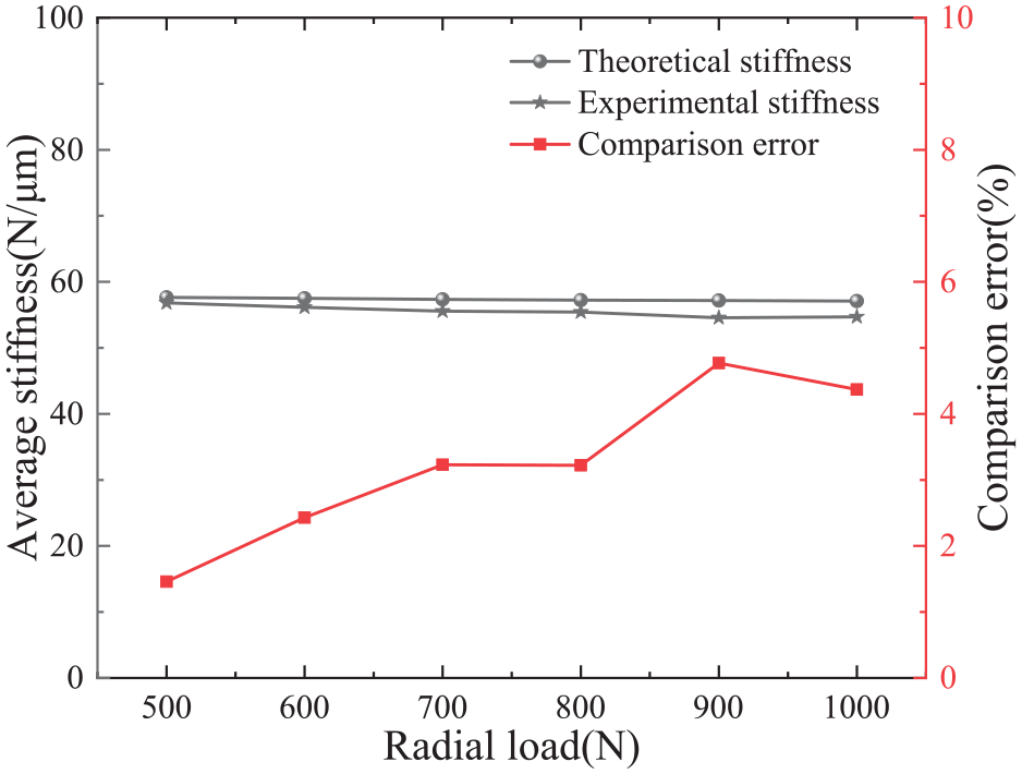
The comparison analysis of experimental and theoretical results.
The test of variable speed and load
The test results for the bearings, with the load increasing from 100 to 1000 N and the rotational speed increasing from 100 to 2000 rpm, are shown in Figure 11. When the rotational speed is constant, the radial displacement of the bearing increases with the radial load. Conversely, when the radial load is constant, the displacement of the bearing increases with the rotational speed.

The load and displacement under the variable speed and load.
The comparative analysis of the bearing stiffness between the experimental and theoretical results, under a radial load of 300 N and a rotational speed increasing from 100 to 2000 rpm, is shown in Figure 12. The stiffness obtained from both tests closely matches the theoretical results. The radial stiffness remains relatively stable across the range of rotational speeds. The maximum error between the experimental and theoretical results is approximately 2.5%, preliminarily verifying the accuracy of the stiffness model.

The comparison analysis of experimental and theoretical results.
Conclusion
For angular contact ball bearings operating at high speeds, the forces acting on the rolling elements are analyzed, taking into account centrifugal force and gyroscopic moment. Equations are derived to calculate the force on a single rolling element and the bearing as a whole. A stiffness model for angular contact ball bearings is established. The established model is verified, and the error is found to be only about 10%.
The analysis explores the effects of rolling element quantity, radial load, and rotational speed on the contact load between the inner and outer rings of the bearing and on its radial stiffness. The findings indicate that within the 0–360° rolling element position angle range, the contact load initially decreases and then increases. A higher number of rolling elements and a lower radial load result in a more evenly distributed contact load. Additionally, increasing the number of rolling elements leads to a nearly linear increase in bearing radial stiffness. On the other hand, an increase in radial load reduces radial stiffness, and it shows weak nonlinearity. Furthermore, at low speeds (<10,000 r/min), radial stiffness remains relatively constant, while at higher speeds, it notably decreases.
The stiffness of the bearing can be determined under various operating conditions using the test signals from force and displacement sensors. Experimental results are then compared with theoretical results. Through the analysis of test data, it is found that the maximum error between experimental and theoretical results is less than 3%. This indicates that the accuracy of the stiffness model is preliminarily verified.
Footnotes
Appendix
Handling Editor: Aarthy Esakkiappan
Declaration of conflicting interests
The author(s) declared no potential conflicts of interest with respect to the research, authorship, and/or publication of this article.
Funding
The author(s) disclosed receipt of the following financial support for the research, authorship, and/or publication of this article: This work is supported by the National Key Research and Development Program of China (No. 2018YFB2000505), the National Natural Science Foundation of China (No. 52108285) and the QinChuangYuan Platform High-level Innovation and Entrepreneurship Talent Projects (No. QCYRCXM-2022-311).