
Abstract
To better realize direction control of the single-pump double-motor hydraulic system and simplify the system, structure and principle of a six-position six-way direction control valve was proposed, which the valve spool has two motion modes: sliding and rotating. Using this valve, the inner and outer motors can work independently and simultaneously. The pressure loss of the valve was tested by building a transmission system, and the experiment results were compared with theoretical analysis. The results show that the performance of the valve working in left and right positions is better than that in meso-position, and the maximum pressure loss occurred in meso-position. Under the rated flow, the maximum pressure loss is 0.331 MPa. Then the characteristic curve of flow-pressure loss and the relationship of pressure loss among oil ports are obtained. In the same conditions, except that the oil inlet pressure loss in the meso-position is greater than the oil outlet pressure loss, the oil inlet pressure loss in the left and right positions are less than the oil outlet pressure loss, the pressure loss in the forward position is less than the pressure loss in the reverse position. The experiment verifies the correctness and feasibility of the structure and principle.
Keywords
Introduction
As a control element to change the direction of oil flow in the hydraulic transmission system, the direction valve is an indispensable basic element to make up the hydraulic transmission.1–3 Especially in the industrial production, equipment manufacturing, engineering machinery, and other fields in the application of hydraulic transmission system,4–6 the number of direction valve needs more, which leads to control complex and the volume of the transmission system is larger.7–9
Faced with this problem, experts and researchers have put forward many solutions. Lyu et al. studied a kind of novel pump and valve combined electro-hydraulic system, the system can achieve high precision tracking and high energy efficiency, while reducing the volume of the system. 10 Li studied deep seawater buoyancy regulating valve manifold, developed the prototype of the valve manifold with the ultra-high pressure buoyancy regulation, and realized the small volume and low weight. 11 In addition, many researchers are also engaged in the study on cartridge valve. Sun and Zhang introduced a two-way buffering valve which is overlapped with the cartridge overflow valve. 12 Tang and Liu studied the dynamic characteristic of three level cartridge valves. 13 Hu and Fan studied the flow-pressure characteristic of small solenoid cartridge valve. 14 There is also some experts study on new structure of multi-way direction valves. 15 Zhang et al. studied on flow field and pressure drop characteristics of main valve dual spool electro-hydraulic proportional multi-way valve. 16 Wang et al. studied the multi-way valve for topology design of groove structure. 17 All of the above studies make the volume of the hydraulic system smaller and the whole system simpler.
The research team engaged in the research and development of hydraulic pump and motor, successfully developed a series of double-stator multi-pumps and multi-motors,18,19 and then formed multi-pump and multi-motor hydraulic transmission.20,21 By direction valve to control the combination and switching of outlet, multi-pump can output a variety of constant flow.22,23 Through the combination and switching of inlet, multi-motor can output a variety of constant torque24,25; both multi-pump and multi-motor have a variety of working conditions. The working conditions of the transmission system composed of the two are more diversified.26–28 Although the commonly used direction valves can satisfy the direction control requirements of the system, more valves are used and the control process is complicated, and this has become a problem of multi-pump and multi-motor hydraulic system.
This paper is organized as follows: section “System direction control requirements” analyzes the reversing requirements of the single-pump and double-motor hydraulic transmission. Section “Principle and function symbol” shows the principle of the electro-hydraulic slide-rotary direction valve. Section “Theoretical comparison” shows theoretical comparison between this valve and the common direction valve in the same transmission. Section “Analysis and experiment of pressure loss” shows the theoretical calculation and testing of the pressure loss, and compares the test result and theoretical result. Section “Conclusion and discussion” draws conclusion and discussion for future research work. The purpose of this study is to present the principle of the direction valve for solving the direction control problem of the single-pump and multi-motor system, test the pressure loss of it and explore the relationship of pressure loss between oil ports in different working positions. The results are expected to provide new method and reference for the direction control of the system, theoretical basis and experimental basis for the research on structure optimization and performance improvement.
System direction control requirements
As the research foundation of adaptive direction valve, the direction control requirements of the single-pump double-motor system should be determined before determining the principle of the direction valve. The system diagram is shown in Figure 1.

Schematic diagram of single pump and double-motor system.
Figure 1 shows schematic of the single-pump double-motor hydraulic transmission. Outer motor working alone, inner motor working alone, and the two motors working together are realized by controlling two direction valves. Combined with forward and reverse working, there are six working conditions. The relationship between the direction control and working conditions of the motor are shown in Table 1. The connectivity of oil way under different working conditions of multi-motor is shown in Table 2.
Relationship between direction control of the valve and double-motor working conditions.

Connectivity of oil way under different working conditions.

From Tables 1 and 2, it can be determined that the direction valve studied in this paper needs six working positions and six main oil ports to complete the direction control requirements in the system. Therefore, a schematic diagram of the oil passing function of the direction valve is established, as shown in Figure 2.
Schematic diagram of oil circulation function.
Figure 2 shows the oil passing function of the direction valve. Oil port P is the inlet of the direction valve; T is the outlet; A/B and a/b are two pairs of working oil ports.
Principle and function symbol
According to the oil circulation function and the functional requirements of six-positions and six-ways, the main valve spool adopts the motion mode of combining slide and rotation, the switch between internal and external motors is controlled by slide, and the forward and reverse oil circulation is controlled by rotation, the working principle is shown in Figure 3.

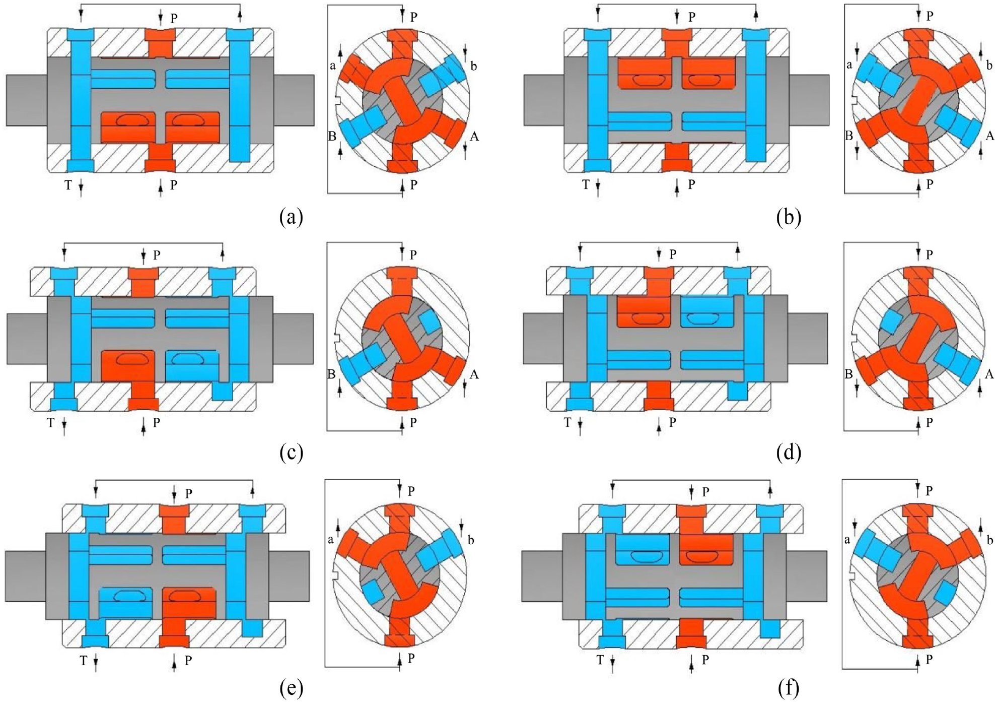
Schematic diagram of direction valve (red color means high pressure oil; blue color means low pressure oil): (a) forward meso-position (axial section), (b) forward meso-position (radial section), (c) reverse meso-position (axial section), and (d) reverse meso-position (radial section).
As shown in Figure 3(a) and (b), the main valve spool in meso-position, meanwhile, the angle between the symmetry axis of the main valve spool and the vertical direction is −θ in the circumferential direction, which is called forward position. Oil port P is connected with A and a at the same time, oil port B and b are connected with T, high pressure oil is supplied to both inner and outer motors to make the multi-motor work forward. The location state of the direction control valve is called the forward meso-position; Keep forward position unchanged, the main valve spool slides to the right, oil port P is only connected with A, and the rest of the working oil port are connected with T, the direction valve is working in forward left position; Similarly, the main valve spool left move, the direction valve is working in forward right position. The main valve spool clockwise forward rotation 2θ to reach the position shown in Figure 3(d), making the valve work in reverse position, and the oil port P is connected with port B or b. Then through the main valve spool axial slide, the reverse meso-position working, reverse left position working, and reverse right position working of the direction valve are completed.
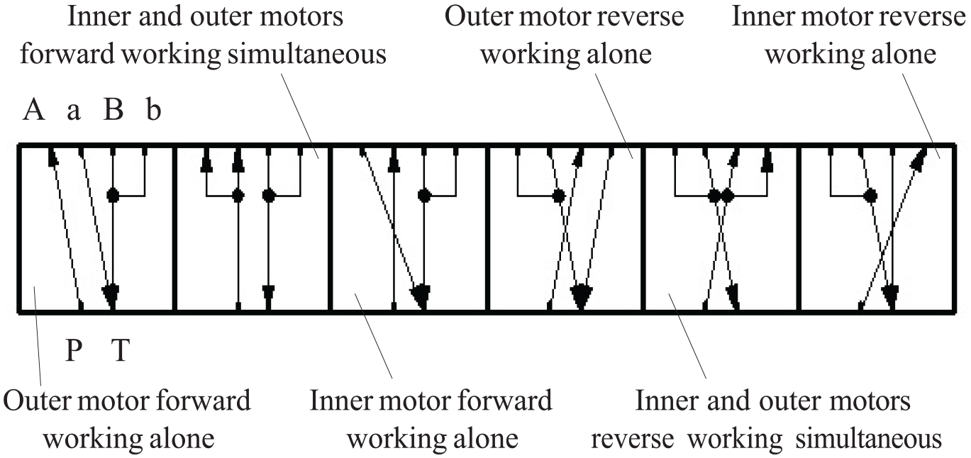
It can be seen from the working principle that the direction valve is a six-position six-way direction valve. The combination of sliding and rotation of the main valve spool forms six working positions of the direction valve, which are forward meso-position, forward left position, forward right position, reverse meso-position, reverse left position, and reverse right position. The connecting states of the oil ports in the actual work of the direction valve are shown in Figure 4.
Working positions and connection status of the valve: (a) forward meso-position, (b) reverse meso-position, (c) forward left position, (d) reverse left position, (e) forward right position, and (f) reverse right position.
The sliding of main valve spool is driven by solenoid pilot valve, and the rotary is driven by stepper motor. In order to express this valve in the hydraulic system diagram, its function symbol is designed, as shown in Figure 5.

Functional symbol of 6/6 electro-hydraulic sliding-rotary direction valve: (a) complete symbol and (b) simplified symbol.
Figure 5(a) shows a full representation of the function symbol, and Figure 5(b) is a simplified representation. The forward rotary of the stepper motor drives the main valve spool to the reverse position and the reverse rotary of the motor returns the valve spool to the forward position.
Theoretical comparison
Direction control of the single pump and double-motor system is carried out by using the 6/6 electro-hydraulic slide-rotary direction valve, as shown in Figure 6, and the direction control process of the direction valve is shown in Table 3.

Diagram of direction control system with the slide-rotary direction valve.
Action sequence table of the slide-rotary direction valve.

As shown in Table 3, “1” and “0” are used to represent the gain and loss of power, and “+” and “−” are used to represent the forward and reverse signals of the stepper motor. “1+” and “1−” respectively mean to give forward and reverse control signals to the stepper motor and keep the power on.
By comparing Figure 1 and Table 1 with Figure 6 and Table 3, it can be seen that to realize the requirements of six working conditions in the single-pump and double-motor system, at least two common direction control valves and four control signals are required for direction control, while only one direction valve and three control signals are needed by using the direction valve studied in this paper.
Analysis and experiment of pressure loss
Theoretical pressure loss
The theoretical formula for calculating fluid pressure loss is

Where λ is the on-way resistance coefficient; l is flow channel length; d is the pipe diameter; ρ is fluid density; v is the average velocity of fluid flow; ζ is local resistance coefficient.
The oil flow passage in the direction valve is short and the resistance along the way is small. Compared with the local pressure loss, the pressure loss along the way is very small. Therefore, the pressure loss along the way is ignored and only the local pressure loss is considered, so the theoretical formula of pressure loss is transformed into

where ζ is local resistance coefficient; ρ is fluid density; A is over-current area; Q is the rate of flow. In the theoretical analysis, because of the structure of the valve spool is symmetry, the factors such as machining accuracy and assembly error are ignored, and it is considered that the pressure loss between the oil ports in the case of forward meso-position, forward left position, and forward right position is the same as that in the case of reverse meso-position, reverse left position, and reverse right position respectively. Because the flow structure from port P to port A (B) is axisymmetric with that from port P to port a (b), it is considered that the pressure loss between port P-A (B) and port P-A (b) is the same.
Considering the flow channel structure and local obstacles encountered during the flow process, based on the local resistance coefficients of common local obstacles, the calculated values show that the local resistance coefficient for meso-position oil inlet is approximately 13.3, while for oil outlet is 10.52; the local resistance coefficient for left and right position oil inlets is 5.32; the local resistance coefficient for left position oil outlet is 7.42, and that for right position oil outlet is 9.55. Through calculation, when the flow rates are 2, 4, 6, 8, and 10 L/min respectively, the theoretical pressure loss of oil ports at six working positions is shown in Table 4.
Theoretical pressure loss at different flow.
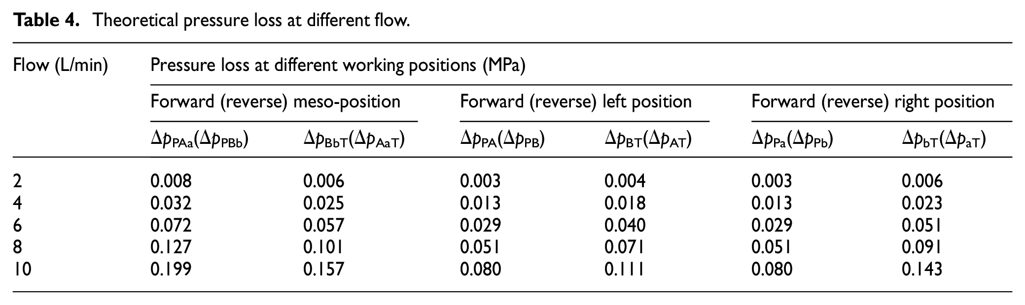
According to the data in Table 4, the pressure loss under the rated flow and the characteristic curve of flow-pressure loss can be obtained, as shown in Figures 7 and 8 respectively.

Comparison diagram of theoretical pressure difference between oil ports at rated flow.

Theoretical characteristic curve of flow-pressure loss.
Experimental pressure loss
The schematic diagram of the test system is shown in Figure 9. The prototype of the main body of the direction valve and experiment system were shown in Figure 10.

Schematic diagram of test system.

Experiment photos: (a) prototype of the main body of this valve and (b) experiment system.
As shown in Figures 9 and 10(b), the test system is mainly composed of quantitative pump 1, overflow valve 2, high-pressure filter 3, pressure gauge 4, prototype 5, electromagnetic pilot valve 6, one-way throttle valve 7, flow meter 8, filter 9, motor 10, pressure gauge switch, pipeline, joint, and oil tank. The pilot solenoid valve of the tested valve is equipped with external oil control source. The quantitative pump 1-1 and 1-2 supply oil to the main oil line and the control oil line of the test system respectively. The relevant parameters of the measuring instruments used are shown in the Table 5.
Relevant parameters of the measuring instruments.

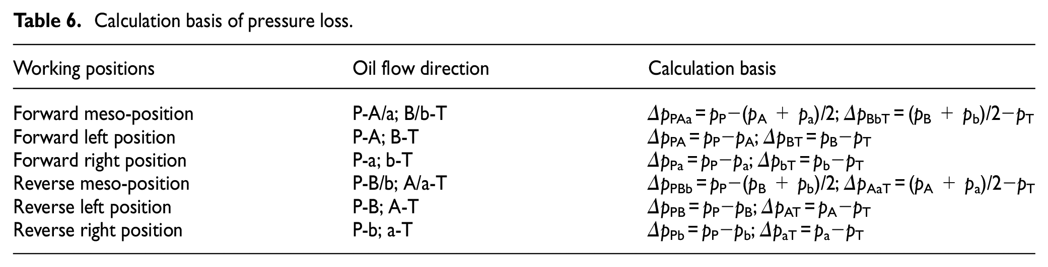
Firstly, control the valve spool of the tested valve at each working position; secondly, adjust the one-way throttle valve 7-1 to gradually increase the flow of the tested valve from 0 to 10 L/min, measure the pressure at the oil port P, T, A, B, a, and b by the pressure gauge. During this process, observe and record the pressure values of each oil port at different flow rates, and calculate the pressure loss between the oil ports on the calculation basis of pressure loss as shown in Table 6, and the pressure loss as shown in Tables 7 and 8.
Calculation basis of pressure loss.
Experimental pressure loss under each flow at three forward working positions.

Experimental pressure loss under each flow at three reverse working positions.

According to the data in Tables 7 and 8, the experimental pressure loss under the rated flow (10 L/min) and the experiment characteristic curve of flow-pressure loss can be obtained, as shown in Figures 11 and 12 respectively.
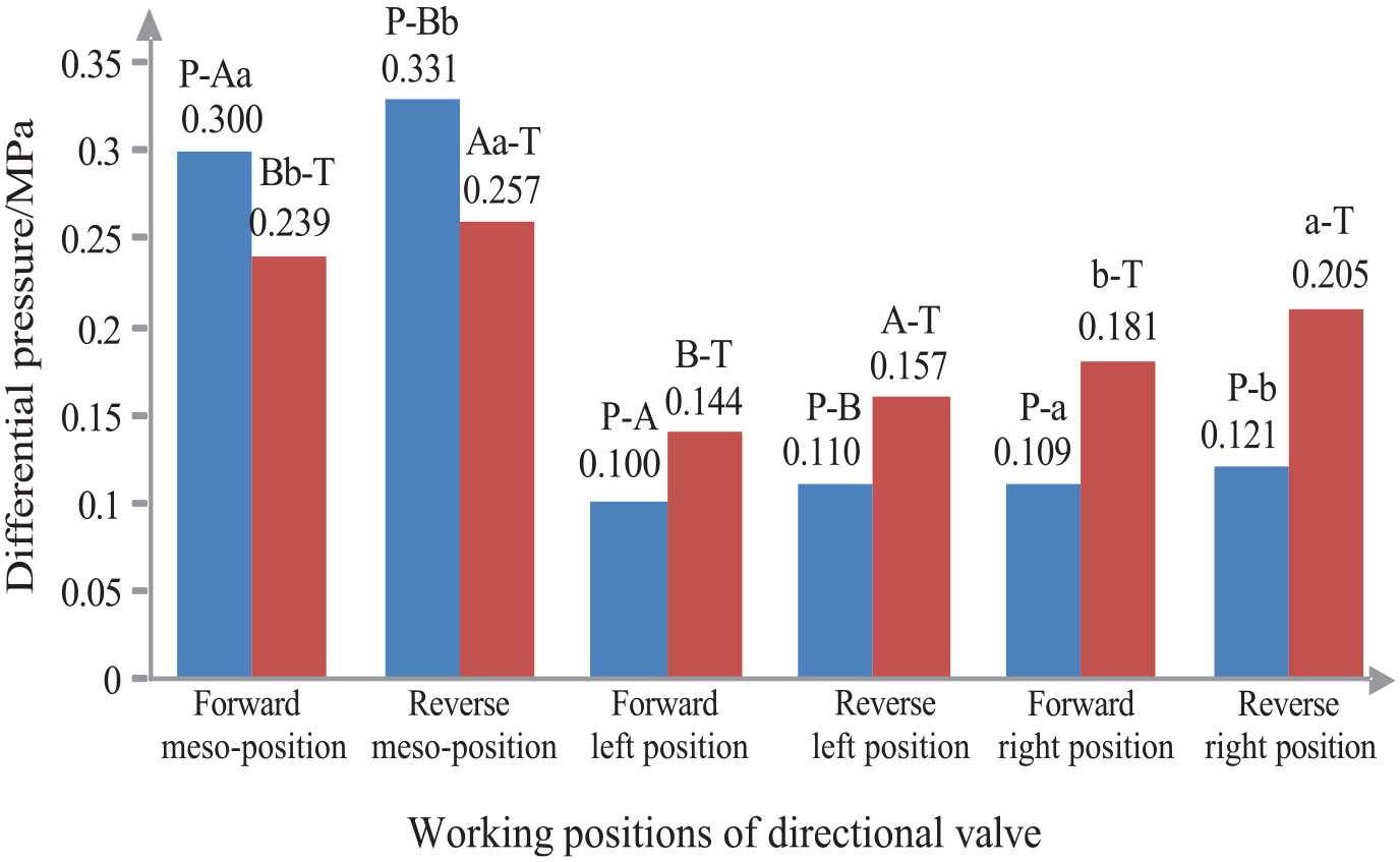
Comparison diagram of differential pressure between oil ports at rated flow.

Test characteristic curve of flow-pressure loss: (a) forward position and (b) reverse position.
As shown in Figure 11, under rated flow, the pressure loss between oil ports in meso-position is significantly higher than that in other working positions. Between oil ports in meso-position, the pressure loss when port P is connected with working port is greater than that when port T is connected with working port, while the pressure loss when port P is connected with working port in the left and right positions is less than that when port T is connected with working port.
As shown in Figure 12(a) and (b), the flow-pressure loss test characteristic curves of the valve under three working states of forward position and reverse position respectively.
Comparison and analysis
Compare Figure 11 with Figure 7, the relationship between experimental pressure loss and theoretical pressure loss under the rated flow was shown in Figure 13. Compare Figure 12 with Figure 8, the comparison relationship between test and theoretical characteristic curve of flow-pressure loss is shown in Figure 14.

Comparison between test and theoretical pressure loss under the same flow condition.

Comparison of flow-pressure loss test curve and theoretical curve: (a) forward position test curve and theoretical curve and (b) reverse position test curve and theoretical curve.
Figure 13 showed the proportional relationship between the experimental and theoretical pressure loss when the flow was the rated flow and the oil ports were connected under the same condition. It can be seen that the maximum pressure loss measured in the experiment is 0.331 MPa. The pressure loss caused by the connection between port P, port B and b in the reverse meso-position increased by 66% compared with the theoretical pressure loss under the same condition. The increasing proportion of it is the largest compared with the pressure loss between other oil ports.
Figure 14 showed the comparison between the experimental and theoretical characteristic curve of flow pressure loss. When the oil ports are connected in the same state, the experiment curves of flow-pressure loss are higher than the theoretical curves, and the change rate of the experiment curve is also higher than that of the theoretical curve with the increase of the flow.
Conclusion and discussion
(1) This paper presents a principle of direction valve adapted to the single-pump and double-motor hydraulic system, and depending on the slide and rotation of a single valve spool to achieve a six–positions and six-way reversing function.
(2) The pressure loss of the valve in the meso-position is greater than that in the left and right positions, which shows that the performance of the direction valve in the left and right positions is better than that in the meso-position.
(3) When the valve works in the left and right positions, the pressure loss of each oil port in forward connection is less than that in the reverse connection, which shows that the performance of the forward position is better than that of the reverse position. While in the meso-position, the performance of the reverse position is better than that of the forward position.
(4) The flow-pressure loss test characteristic curves were obtained. The relationship between the experiment results and the theoretical calculation is consistent, and the change trend and distribution of the experimental characteristic curve are the same as the theoretical characteristic curve, and the results of pressure loss experiment are consistent with the theoretical expectations.
The reason why the experiment data is higher than the theoretical value may be due to the influence of pressure loss along the way; during the confluence process, the oil in different directions collides with each other to increase the pressure loss; when the valve is working in the meso-position, the oil diverts and impacts the middle shoulder of the main valve spool, resulting in a large pressure loss. In addition to the above, processing accuracy, assembly accuracy, oil impurities also lead to deviations between the experiment results and the theoretical values.
In summary, the experiment verifies the correctness and feasibility of the principle of electro-hydraulic slide-rotary direction valve. The proportional relationship between the pressure loss of the valve at each working position and the variation rule of the pressure loss between the oil ports are revealed. This paper provides the experimental basis for the follow-up research.
Footnotes
Handling Editor: Aarthy Esakkiappan
Declaration of conflicting interests
The author(s) declared no potential conflicts of interest with respect to the research, authorship, and/or publication of this article.
Funding
The author(s) received no financial support for the research, authorship, and/or publication of this article.