
Abstract
Since the wave is accompanied by the transfer of energy in the process of transmission, and the energy density at the node directly affects the bearing capacity and service performance of the steel truss cable-stayed bridge members and joints, this paper quantitatively studies the energy density at the key nodes of the long-span steel truss cable-stayed bridge from the perspective of the wave response of the structure. Firstly, according to the drawings of Xiangshan Bridge, a local finite element model of the steel truss cable-stayed bridge is established, and by changing the angle between the cable and the steel truss girder and the bending stiffness of the cable, the variation law of energy density at the connection node between the cable and the steel truss girder is obtained by changing the angle between the cable and the steel truss girder and the bending stiffness of the cableway. Due to the limitations of finite element wave analysis, from the perspective of theoretical analysis, this paper establishes the local scattering matrix at the node, proves the obtained law to a certain extent, and uses the return wave-light matrix method to analyze and solve the energy density at the connection node between the cable bar and the steel truss girder, and the final analytical solution is in good agreement with the numerical solution, which proves that the law obtained by numerical analysis is correct.
Keywords
Introduction
Current research suggests that the dynamic response of a structure subjected to impact loading is effectively characterized by waves propagating throughout the structure. 1 In the context of bridge engineering, the propagation patterns of stress waves are crucial in determining the structure’s initial dynamic response. However, these patterns are often neglected in prevailing design codes, which may lead to unintended structural damage. This oversight is particularly critical in large-span beam-cable systems, such as cable-stayed, suspension, through-arch, or half-through arch bridges. In these structures, the propagation of stress waves must be accounted for, especially since the load application occurs within a time frame comparable to, or shorter than, the duration needed for stress waves to traverse the structure’s characteristic length. 2
Despite the limited research on stress wave propagation in cable-beam systems, insights can be gleaned from studies on similar engineering structures. Guo et al. 3 utilized the finite element method to model the propagation of stress waves in laminated plates. Their study elucidated the propagation patterns, damage, and destruction characteristics of these waves, and proposed an optimized layering sequence of composite materials to mitigate damage from low-speed impacts. Mohsen et al. 4 employed the Wave Finite Element Method (WFEM) for simulating wave propagation in one-dimensional variable cross-section non-uniform linear micro-polar rods, addressing wave propagation, reflection, transmission, and impact phenomena. Furthermore, Tang et al. 5 analyzed wave propagation and dispersion in infinite Timoshenko beams with periodic resonators, contributing to seismic design knowledge. However, these studies predominantly focus on semi-infinite engineering structures, whereas this research is concerned with a finite structural system.
Investigating wave propagation in finite engineering structures necessitates examining stress wave distribution at nodes 6 and discontinuities. 7 Pioneering work by Lee and Kolsky 8 focused on the generation of stress pulses at the intersection of two non-collinear rods. Building on this, Abadi 9 analyzed the reflection and transmission coefficients of waves at joints and explored the energy distribution of elastic waves in these areas. Subhash et al. 10 research, adopting both analytical and numerical approaches, analyzed longitudinal elastic stress wave propagation through a 180° bend connecting two square rods. The findings validated the applicability of one-dimensional stress wave theory in simulating long-duration stress pulses around such bends. Similarly, these studies collectively inform this research, particularly in deducing the scattering behavior of stress waves within the structure. This is achieved by synchronizing displacement coordination at nodes with force balance, enabling the establishment of displacement function constraints for both beams and cables.
Prior research has predominantly concentrated on the propagation of free waves in semi-infinite bodies, while the propagation of stress waves in engineering structures subjected to impact loads has received comparatively less focus. Investigating the patterns of stress wave propagation due to impact loads in specific structures holds substantial engineering importance. However, there exists a notable gap in research in this area. To effectively understand the general characteristics of stress wave propagation in steel truss cable-stayed bridges under impact load, an initial examination of the structure’s transient response is essential.
Some progress has been made in the study of the transient response of structures subjected to shock loads. The differences in the methods used to study this response depend mainly on the method used to solve the dynamic equations. These methods include, but are not limited to, the transfer matrix method of Pestel and Leckie, 11 the eigenfunction expansion method of Song et al.,12,13 the hypothetical displacement function method of Lu and Li, 14 and the explicit finite element method of Rafiee-Dehkharghani et al. 15 However, these methods used to analyze the dynamic response are not effective in obtaining direct expressions in the form of fluctuations in the dynamic equations. Therefore, it is important to find a dynamic analysis method that utilizes traveling wave solutions.
The reverberant ray matrix (MRRM) method proposed by Howard and Pao 16 initially focused on longitudinal wave propagation in the structure, and the results obtained were in good agreement with the experimental data only in early agreement. Pao et al. 17 took bending and shear waves into the calculation of the method, which significantly improved the accuracy of the method. After the introduction of MRRM, many researchers have applied MRRM to study the transient response of structures under shock loads. Notably, Wei et al. 18 applied MRRM to study the free vibration and dynamic response of piles semi-rigidly connected to the superstructure, demonstrating the effectiveness and accuracy of MRRM in dynamic analysis. Li and Nie 19 applied MRRM to the buckling analysis of a multi-span rectangular sheet with internal stiffeners and proposed a matrix algorithm to determine the buckling load of the sheet. Ji et al. 20 analyzed the transient response of beam-cable composite structures under motion loads, and proposed a series of solutions based on the concept of Discrete Fourier Transform (DFT), and achieved certain results. MRRM can also be used to accurately predict layered structures, 21 transient responses of continuous beams under motion loads, 22 layered beams, 23 and cylindrical shell structures. 24 Together, these studies affirm the reliability and versatility of MRRM in solving structural dynamic response problems. However, previous studies have focused on single-form structures, ignoring more complex systems, such as the cable girder systems discussed in this article. The MRRM method elucidated the transient response of the structure through the propagation and superposition of stress waves. Therefore, the MRRM method is used to derive the analytical solution of the dynamic response of the cable-stayed beam under impact load.
This paper explores the impact of stress wave propagation, which entails energy transmission, on the load-bearing capacity and performance of the steel truss cable-stayed bridge’s components and nodes, given that energy density during this propagation is a critical factor. To this end, the study quantitatively investigates the energy density at the cable-beam connection nodes within the steel truss cable-stayed bridge, utilizing the wave equation in conjunction with both the finite element method and the Matched Reciprocal Wave Return Matrix Method (MRRM). The objective is to furnish foundational insights for the structure’s design optimization.
Analysis of factors affecting the energy density at the connection nodes of cable-stays and steel trusses
Establishment of a local finite element model
The finite element analysis software ABAQUS was used for modeling, and the local model is shown in Figure 1. The lower steel truss was simulated using beam elements, and the cables were simulated using truss elements. The model dimensions for each component were based on a 1:1 scale of the Xiang Shan Bridge, a large-span steel truss cable-stayed bridge, The main span of Xiangshan Bridge is 880 m, the total length of the bridge is 1776 m, and the specific distribution of spans is 136 m + 312 m + 880 m + 312 m + 136 m. The bridge structure diagram is shown in Figure 1. In the figure, BC and GI represent the cables of the cable-stayed bridge, and the rest represent the steel truss girders. The length of each chord member segment is 12.8 m, the vertical web member is 10 m, and the diagonal web member is 16.24 m. The cross-sectional shape of the beam element is box-shaped, with the upper and lower chord members having the same cross-sectional dimensions: width 1.2 m, height 1.8 m, and thickness 0.02 m; the vertical and diagonal web members also have the same cross-sectional dimensions: width 1.0 m, height 1.2 m, and thickness 0.02 m; the cross-sectional area of the cable is 0.02 m2. The material parameters for the beam are: modulus of elasticit

Schematic diagram of the local finite element model of the steel truss cable-stayed bridge and bridge structure.
The boundary conditions at the bottom of the steel truss are fixed at both ends where the two cables are located.
Determination of vehicle impact load
The impact load of vehicles on bridges is mainly caused by the unevenness of the road surface. In existing studies, Yu et al. 21 have approximated the impact load of vehicles on bridges as a sine function, as shown below:

In equation (1),

Schematic diagram of vehicle axle load.

Time-domain diagram of impact load.
Determination of analysis steps
In structural analysis utilizing wave theory, it is imperative to account for the propagation of disturbances, which manifests as the transmission of waves within the structure. This propagation is multi-path in nature, introducing a fundamental distinction between wave analysis and overall response analysis, particularly in terms of time lag considerations.
According to wave theory, the wave speeds of longitudinal waves and bending waves are respectively:


In these equations,
When the impact load is applied to point E, the stress wave generated by the structure starts to propagate from point E to each point, and when the stress wave is transmitted to the next node, the wave will be transmitted and reflected at this node, and the transmitted wave and reflected wave will be generated in other members and continue to propagate in the structure. The path of stress wave propagation from point E to point B is shown in Figure 4.
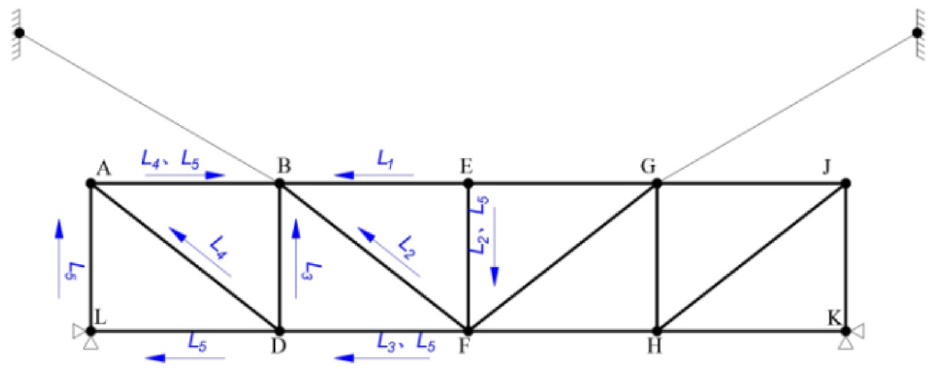
Stress wave propagation path diagram.
As can be seen from the Figure 4, there are five different paths for the wave to travel from point E to point B, each calculated using the bending wave speed of 1181 m/s. The arrival times of the bending waves for the five paths are shown in Table 1.
Propagation times of stress waves on different paths.

As previously noted, the load duration is a mere 6 × 10⁻³ s, a timespan insufficient for the bending wave to reach the joint where the cable and steel truss connect. Consequently, for effective wave motion simulation, it is essential to implement two distinct analysis steps. The initial excitation, corresponding to the aforementioned impact load, is applied at node E. The first analysis step incorporates a time step of 6 × 10⁻³ s, coinciding with the cessation of the impact load. The second step extends over a duration of 1 s, ensuring adequate time for both longitudinal and bending waves to traverse the structure. During this propagation, waves undergo reflection and transmission at the node, and this process repeats with the return of the reflected waves, thereby increasingly complicating the wave propagation. This complexity continues to evolve until it effectively represents the overall structural response.
To gain a clearer understanding of stress wave propagation in steel truss cable-stayed bridges, this study examines the impact of the angle and bending stiffness of structural members on the energy density at the cable-beam connection nodes.
Influence of cable inclination angle on energy density at the connection node of cable and steel truss
In the process of stress wave propagation, it is accompanied by energy transmission, and the energy density in the process of stress wave propagation directly affects the bearing capacity and service performance of steel truss members and joints. The greater the energy density, the greater the energy concentrated in a short period of time, and the easier it is for the node to be destroyed.
This research investigates the impact of the cable inclination angle on the energy density at the connection node between the cable and the steel truss. To this end, five distinct local finite element models were developed, each varying solely in the cable’s inclination angle, which ranged from 20 to 60 degrees, while maintaining all other conditions constant. Upon completing the simulations, the energy density at the connection node was extracted. The results of these finite element calculations are presented in Figure 5.

Energy density at the connection node of cable and steel truss at different angles; (a) 20°; (b) 30°; (c) 40°; (d) 50°; (e) 60°; (f) comparison between 20° and 60°.
To delve deeper into how the energy density at the connection node varies with the cable’s angle, a statistical analysis of the peak values of the first wave peak of the energy density at each angle was conducted. The findings of this analysis are presented in Table 2 and Figures 6 and 7.
Peak values of energy density at the connection node of cable and steel truss.


Variation of energy density at the node with angle.

Variation of energy density wave peaks at different angles.
The energy density during stress wave propagation critically influences the load-bearing capacity and functionality of the components and joints of the steel truss cable-stayed bridge. A higher energy density over a brief duration implies a more concentrated energy distribution during that period, increasing the likelihood of damage to the node. Analysis of the peak values of the first wave peak of energy density at different angles reveals a clear trend: as the cable inclination angle increases, the energy density at the connection node between the cable and the steel truss decreases. This decline, as depicted in Table 2, Figures 6 and 7. is relatively uniform without abrupt fluctuations. Additionally, Table 2 indicates that all wave peaks occur simultaneously at 0.11 s, suggesting that changes in the inclination angle do not alter the fundamental nature of stress wave propagation in the structure but affect the transmission and reflection of stress waves at the node.
The findings from the aforementioned numerical simulations lead to an important inference: enhancing the cable inclination angle positively impacts the performance of the connection node between the cable and the steel truss.
Influence of member bending stiffness on energy density at the connection node of cable and steel truss
Equations (2) and (3) establish that the velocity of longitudinal waves in a structure depends solely on the material’s modulus of elasticity and density. In contrast, the velocity of bending waves is influenced by additional factors including the member’s cross-sectional area, moment of inertia, and the wave’s circular frequency. Building on this foundation, the study examines the impact of bending stiffness of structural members on the energy density at the cable and steel truss connection node. Given that the modulus of elasticity remains constant for a specific material, the moment of inertia for a circular section is derived as per the principles of material mechanics:

Where
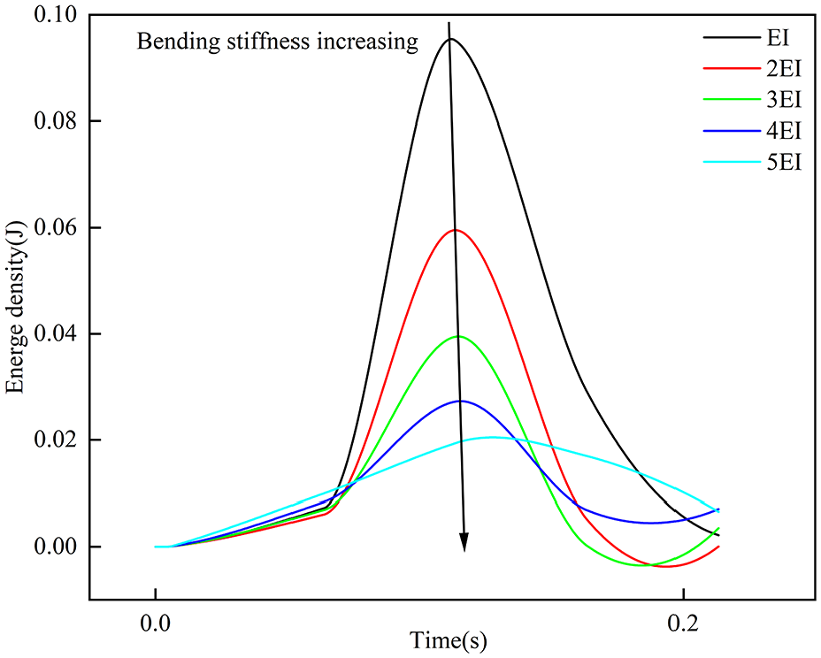
In a similar manner to the angle simulation, five finite element models were created, each varying solely in the radius of the cable’s cross-section to alter the cable’s bending stiffness. These variations maintained all other parameters constant. The bending stiffness in the numerical simulations was set at EI, 2EI, 3EI, 4EI, and 5EI, respectively.
The numerical simulation results are shown in Figure 8.

Energy density at the connection node of cable and steel truss under different bending stiffness; (a) EI; (b) 2EI; (c) 3EI; (d) 4EI; (e) 5EI; (f) comparison between EI and 5EI.
Mirroring the approach used in analyzing the impact of angles, this study extends its investigation to examine how the bending stiffness of the cable affects the energy density at the connection node. A statistical analysis was conducted on the peak values of the first wave peak of energy density under each varying condition. The outcomes of this analysis are detailed in Table 3 and Figure 8.
Peak values of energy density at the connection node of cable and steel truss.

The energy density during stress wave propagation critically influences the load-bearing capacity and functionality of the components and joints of the steel truss cable-stayed bridge. A higher energy density over a brief duration implies a more concentrated energy distribution during that period, increasing the likelihood of damage to the node. The numerical analysis results reveal that, akin to the trends observed with angular adjustments, an increase in the cable’s bending stiffness leads to a decrease in the peak value of energy density at the connection node between the cable and steel truss. Notably, these peak values consistently occur at 0.11 s, suggesting that alterations in the cross-sectional area do not modify the fundamental nature of stress wave propagation within the structure; rather, they affect the degree of transmission and reflection at the node.
Analyzing Figures 9–11 demonstrates a distinct contrast between the outcomes of the bending stiffness analysis and those of the angle influence analysis. Specifically, the reduction in energy density at the node due to increased bending stiffness initially occurs rapidly, then gradually tapers off. In contrast, the reduction attributed to changes in angle is relatively uniform throughout. Therefore, altering the bending stiffness significantly impacts the energy density at the node initially. However, beyond a certain level of increased bending stiffness, the influence of further increments diminishes, leading to a scenario where further changes in bending stiffness might result in negligible or only minimal changes in the node’s energy density.

Variation of energy density at the node with cross-sectional ratio.

Variation of energy density wave peaks under different bending stiffness.

Variation of energy density at the node with cross-sectional ratio.
In optimizing parameters at the connection node, prioritizing changes in the bending stiffness of the connecting members is recommended. Should alterations in bending stiffness fail to yield the desired outcomes, further adjustments in this aspect may prove uneconomical. Under such circumstances, adjusting the cable’s inclination angle to optimize the energy density at the node becomes a more viable strategy than continuing to modify bending stiffness.
The analysis presented in this section leads to several key conclusions:
Increasing the cable’s bending stiffness results in a reduced energy density at the connection node between the cable and the steel truss, thereby enhancing the node’s load-bearing capabilities.
Modifying the bending stiffness has a more pronounced effect on optimizing energy density at the node compared to altering the cable’s inclination angle. However, the effectiveness of bending stiffness adjustments reaches a plateau.
Changes in bending stiffness do not impact the fundamental nature of stress wave propagation within the structure; their influence is confined to modifying the transmission and reflection intensity at the node.
Theoretical verification of numerical analysis results
Given the often idealized nature of parameter selection and boundary conditions in numerical analysis, and considering that ABAQUS’s explicit dynamic analysis module employs the central difference method, which is not prone to convergence issues, the accuracy of final results cannot be assured. Consequently, validation of the laws and results obtained from numerical analysis is imperative. This section aims to confirm the patterns of energy density variation at the node, as deduced from the previous two sections, through the lens of wave theory. The subsequent section will develop an analytical solution for the node’s energy density and juxtapose it with the numerical solution, to ascertain the validity of the numerical simulation.
In wave theory, the formula for calculating the energy density of a wave is:

where the variables
From the provided formula, it becomes evident that in the analysis of influencing factors in the preceding two sections, only the wave amplitude has undergone changes, while other factors remained constant. To theoretically examine the pattern of energy density variation at the node concerning alterations in angle and bending stiffness, it becomes imperative to scrutinize the wave amplitude’s behavior under such variations.
When stress waves reach the node, they undergo reflection and transmission processes. To theoretically validate the laws deduced from the numerical simulation analysis, it becomes necessary to formulate expressions for reflection and transmission at the node, with the wave amplitude as the primary variable of interest.
The derivation process of the local transmission matrix at the connection node between the cable and the steel truss is presented below:
To determine the propagation pattern of stress waves at the node, a theoretical model is first established, as shown in Figure 12. In this model, CE, CF, CD, and CA represent the steel trusses connected to the node, while CB represents the cable connected to the node. The modulus of elasticity for the steel trusses is

Theoretical model and coordinate system.
An incident wave enters from end E of truss CE and propagates to node C, where reflection and transmission processes take place. The reflected wave comprises both longitudinal and bending waves, and similar transmission of longitudinal and bending waves occurs in each of the adjacent trusses, as indicated in Figure 12. Cable CB carries transmitted longitudinal and transverse waves, with their respective sign conventions detailed in the local coordinate system depicted in Figure 12.
The analysis assumes that the node is rigid, and upon the incident wave reaching the node, it undergoes solely translational movement without rotation. The longitudinal displacement of the node is denoted as
To determine the reflection and transmission waves in each member, a total of 10 unknowns must be solved, necessitating the formulation of 10 nonlinear independent equations for a solution. These equations can be established in the overall coordinate system based on the displacement coordination at the node.
For truss CE:


For truss CF:


For truss CD:


For truss CA:


For cable CB:


Further, the balance of forces at the node in the overall coordinate system can be established as follows:
In the U direction:

In the W direction:

where m is the mass of the node,
The internal forces of the members are represented by the constitutive equation:


Where
According to wave theory, the displacement function of a wave’s mass point is assumed as:


Where
For simplicity, let’s consider only one term of the wave’s mass point displacement function for discussion, which does not affect the wave propagation pattern. Since the incident wave undergoes reflection and scattering at the node, the node is set as the origin, that is, x = 0.
Substituting the mass point displacement function into the displacement balance equation and force balance equation, simplifying, and representing the equation system in matrix form gives:


Coefficients in the matrix S are:


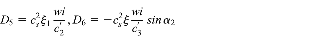


Where
In the equation (15),
In the analysis of the influence of cable inclination angle on the energy density at the connection node, only the angle between the cable and the steel truss changed, while other factors remained constant. It is assumed that the change in cable inclination angle only affects the wave amplitude in the cable, with the wave amplitudes in other connected members remaining unaffected. In the outgoing matrix,
Isolating the equations regarding cable inclination angle and wave amplitude for analysis gives:

In numerical analysis, the cable is modeled as a truss element, which only deforms axially without transverse deformation. In reality, the cable does have transverse deformation, but it is very small. Thus, it is negligible in the analysis, forming a function of
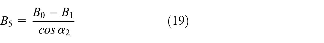
Where

Theoretical wave amplitude variation curve.
From the Figures 13 and 14, it can be seen that in theoretical analysis, as
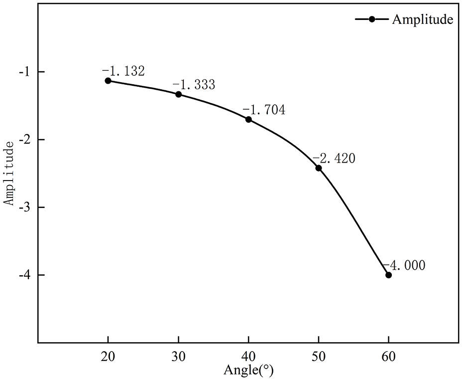
Theoretical energy density variation curve.
Similarly, equations related to the cable bending stiffness and wave amplitude are isolated:

where parameters containing the cable section radius include

Although both numerical and theoretical analyses indicate a similar general trend in the influence of the cable’s inclination angle on energy density, their variation patterns differ. Numerical analysis shows a gradual shift in energy density with inclination angle, whereas theoretical analysis reveals a pattern that initially changes slowly and then accelerates.
This divergence primarily stems from the theoretical assumption that wave amplitude in the cable varies solely with inclination angle, while amplitudes in connected components remain constant. Subsequent analysis will demonstrate the actual impact of this assumption. Additionally, the theoretical model’s exclusion of transverse waves in the cable contributes to the observed differences in energy density variation rates.
To ascertain the impact of bending stiffness on nodal energy density and further explore the effect of cable inclination angle, we analytically computed and compared nodal energy density values with numerical solutions, thereby offering a precise validation of the nodal energy density variation pattern.
Comparison of numerical and analytical solutions
The preceding section established the necessity of determining the incident and outgoing wave amplitudes at the connection node between the cable and the steel truss to derive an analytical solution for the node’s energy density. This involves solving the transient response of the structure under an impact load.
There has been considerable research on the wave analysis of frames and trusses. Main analysis methods include the transfer matrix method, direct stiffness method, traveling wave method, and the method of reverberation-ray matrix (MRRM). This study uses the MRRM method for analyzing the local model.
The MRRM method’s solution process involves several steps: Establishing a local coordinate system for each structural member and numerating each node. A different origin point within the same member alters its relationship with the local coordinate system.
Formulating wave equations for each structural unit in the local coordinate system, followed by applying the Fourier transform to transition these equations from the time to the frequency domain. Waves are classified as outgoing or incoming based on their direction, with their amplitudes remaining undetermined.
In the global coordinate system, equations are formed based on nodal displacement coordination and force equilibrium. The internal forces of units are derived from constitutive relations. The scattering matrix for each node is determined using the incoming wave amplitudes, which are then assembled in accordance with node numeration to compose the overall structure’s scattering matrix.
The outgoing wave from one node, upon reaching the next node, becomes the incoming wave for that node. The phase difference, corresponding to the travel time of the wave between nodes, is used to construct the phase matrix for each unit. These matrices are then compiled based on node numeration to form the overall phase matrix of the structure. Finally, using the combined scattering and phase matrices, the characteristic equation of the MRRM method in the frequency domain is established:


Where

The matrix
In theory, the outgoing and incoming wave amplitudes can be deduced from the previously mentioned equation. Subsequently, applying the Fourier inverse transform converts these results from the frequency to the time domain, facilitating the calculation of the node’s energy density. Nonetheless, when the frequency
In the numerical analysis of nodal energy density, constraints of finite element software limit the extraction of energy density to one end of a structural member, representing the node’s energy density. In this study, the chosen point is the C end of beam CE. Consequently, the wave amplitudes and energy density derived analytically also pertain to the C end of beam CE.
Utilizing the wave amplitude data, along with equation (5), we derived analytical solutions for the node’s energy density, which were then juxtaposed with their numerical counterparts. The comparative outcomes are depicted in Figures 15 and 16.

Comparison of numerical and analytical solutions under the influence of cable inclination angle; (a) 20°; (b) 30°; (c) 40°; (d)= 50°; (e) 60°.

Comparison of numerical and analytical solutions under the influence of bending stiffness (a) EI; (b) 2EI; (c) 3EI; (d) 4EI; (e) 5EI.
The peak energy density values at the connection node between the cable and steel truss were determined both numerically and analytically. The discrepancies between these values were calculated, with the findings presented in Tables 4 and 5.
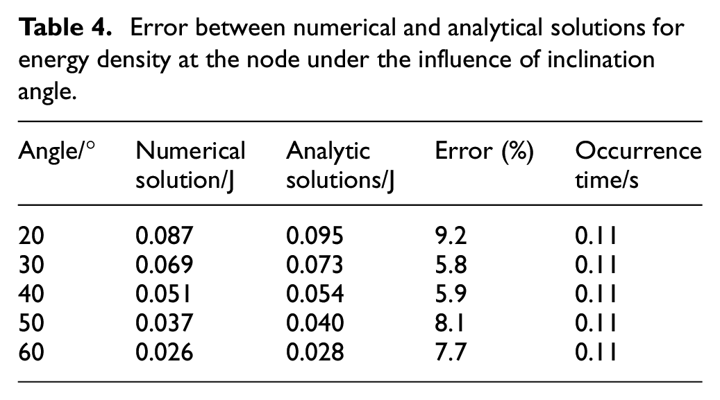
Error between numerical and analytical solutions for energy density at the node under the influence of inclination angle.
Error between numerical and analytical solutions for energy density at the node under the influence of bending stiffness.
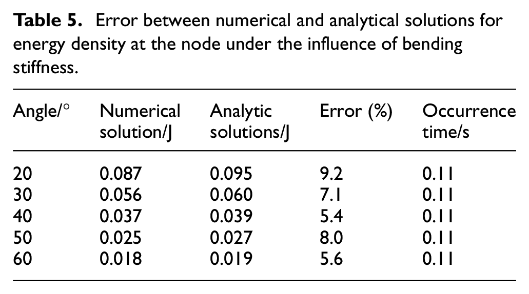
Analysis of Figures 17 and 18 and Tables 4 and 5 reveals that the analytical solutions derived via the reverberation-ray matrix method closely align with the numerical solutions computed using ABAQUS, the maximum deviation being 9.2%. This reinforces the validity of the previously drawn conclusions. Notably, the analytical solutions are predominantly higher than their numerical counterparts, attributable to the implementation of artificial damping as volume viscosity in ABAQUS’s finite element wave analysis, which causes energy dissipation during the finite element time history analysis.

Peak variation of energy density in analytical solution at different angles.
Peak variation of energy density in analytical solution under different bending stiffness.
Conclusion
This chapter presents a quantitative analysis of energy density at critical nodes in a large-span steel truss cable-stayed bridge, emphasizing the impact of structural wave response on the load-bearing capacity and functionality of the bridge’s members and joints. The study began with the construction of a 1:1 scale local finite element model of the bridge, using the Xiang Shan Bridge blueprints as a reference. The initial excitation was modeled as an impact load resulting from road surface irregularities, and the analysis step time was tailored to the speed of stress wave propagation within the structure. Variations in the energy density at the juncture of the cable and steel truss were investigated by altering the cable’s angle and bending stiffness. Given the constraints of finite element wave analysis, a theoretical approach based on wave theory was also employed. This involved establishing a local scattering matrix at the node and applying the reverberation-ray matrix method to analytically determine the node’s energy density. The congruence between the analytical and numerical solutions, with a maximal discrepancy of 9.2%, validates the accuracy of the identified energy density variation patterns in the numerical analysis. The research findings in this chapter lead to the following conclusions:
An increase in the cable’s inclination angle under consistent load conditions leads to a notable decrease in the peak energy density at the node connecting the cable and steel truss. Specifically, as the angle increases from 20° to 60°, the node’s energy density diminishes from 0.087 to 0.026 J, a 3.34-fold reduction. This finding underscores the significant influence of cable inclination angle in engineering applications, particularly for enhancing the node’s load-bearing performance.
Similarly, an increase in the cable’s bending stiffness results in a decrease in peak energy density at the same node. An increase in stiffness from EI to 5EI reduces the energy density from 0.087 to 0.018 J, equating to a 4.83-fold decrease, which is more pronounced than the effect of increasing cable inclination. Interestingly, the reduction in energy density is more gradual with increased cable inclination compared to increased cross-sectional area ratio of the cable and steel truss. Therefore, in engineering practice, adjusting the cross-sectional area is prioritized over altering cable inclination. However, once the effect of cross-sectional area modification diminishes, the adjustment of cable inclination becomes more significant.
In a node connected to multiple members, altering one member’s parameters affects the intensity of reflected and transmitted waves in the other members, but does not influence the speed of stress wave propagation in them.
The reverberation-ray matrix method effectively calculates the transient response of a local steel truss cable-stayed bridge model under impact load. The analytical outcomes closely match the numerical results, with deviations ranging from 5.4% to 9.2%, confirming the method’s accuracy. Generally, theoretical values exceed numerical ones, attributed to wave energy dissipation in ABAQUS’s finite element wave analysis.
The numerical simulation in this paper uses a 2D model, and the real bridge should be simulated using a 3D model. With the development of engineering technology, the span of the bridge will become larger and larger, and the consequent stress wave problem will become more and more obvious. The research in this paper provides a certain reference and idea for the subsequent research on the dynamic response characteristics of bridges.
Footnotes
Handling Editor: Sharmili Pandian
Declaration of conflicting interests
The author(s) declared no potential conflicts of interest with respect to the research, authorship, and/or publication of this article.
Funding
The author(s) disclosed receipt of the following financial support for the research, authorship, and/or publication of this article: The research described in this paper was financially supported by Guangdong Basic and Applied Basic Research Foundation (Grant No. 2021A1515012405).