
Abstract
Aiming at the problems of insufficient loading dimension and difficult engineering application of CNC machine tool reliability test device, a low-cost, recyclable multi-dimensional force tracking-loading simulator is developed based on the conical test piece. First of all, according to the principle of homogeneous coordinate system transformation and rigid body hypothesis theory to establish a five-axis machining center cutting force model, derive the cutting force expression of the machining center during the cutting process. Secondly, based on Ansys, the super elastomer rubber ring model for loading is established, and through nonlinear dynamics simulation, it explores the change rule of the integrated force on the spindle with different cutting depth and rubber ring thickness. Then, the loading test is carried out on a five-axis linked machining center to verify the feasibility of the multi-dimensional force tracking-loading simulator and the multidimensional loading capacity, which provides a new loading mean and theoretical basis for the reliability test of CNC machine tools. Finally, by comparing the simulation and experiment results, it is concluded that when the rubber ring thickness is 3 mm, the comprehensive cutting force fluctuation of the five-axis machining center is the smallest, and the relative error between the experiment comprehensive force and the simulation comprehensive force is 19.8%, which is the best thickness of the rubber ring under loading test.
Keywords
Introduction
CNC machine tools are the working machines of the equipment manufacturing industry, 1 and its technical level is an important symbol for evaluating a country’s comprehensive strength and manufacturing modernization level. In particular, the five-axis machining center has a unique advantage in the processing and manufacturing of complex curved surface workpieces due to its high degree of freedom, and is widely used in aerospace, rail transit, mold manufacturing, and other fields. At present, CNC machine tools have made significant progress in speed, accuracy, multi-axis linkage, composite functions, and intelligence. However, the reliability problem is prominent in the process of operation, such as high failure rate, advanced functions can not be maintained.2,3 Therefore, improving the reliability level of CNC machine tools is an urgent problem to be solved.
CNC machine tool is a set of electromechanical, hydraulic and pneumatic is equal to the integration of complex electromechanical products. 4 Compared with three-axis cutting, five-axis machining center introduces two additional rotational degrees of freedom, which has complex structure, high degree of technological integration, coupled with variable working conditions, resulting in a substantial increase in the probability of its failure. CNC machine tool products in order to achieve the specified performance parameters, before delivery must carry out a large number of reliability tests. In order to find the failure of the machine tool operation, conventional CNC machine tool reliability test 5 through a long time cutting process. There is a long cycle, high cost, wear and tear on the tool, and the need for a large number of cutting samples and other shortcomings, can not be quickly assessed and evaluated the reliability of the CNC machine tool. Therefore, there is a need to carry out a new type of CNC machine tool reliability simulation test, which is to develop a low-cost, recyclable multi-dimensional force tracking-loading simulator. And tracking the machine tool machining path and applying multi-dimensional cutting force loads subjected to the actual cutting process, instead of conventional CNC machine tool reliability test of the metal cutting process.
At present, the National Center for Quality Supervision and Inspection of Machine Tools Zhao Qinzhi, 3 Jilin University Yang Zhaojun, 4 Tsinghua University Wu Jun, 5 China Academy of Engineering Physics Chen Heng,6,7 etc., mainly realized the reliability test of CNC machine tools one-dimensional force load following the load, the test time is long, the effect is poor, and can not be directly applied to the spindle multi-dimensional force load in the test. In order to solve the problem of insufficient loading dimension of the loading device, some researchers proposed the method of multidimensional loading test with parallel mechanism. For example, Zhang et al. 8 at Tsinghua University developed a three-degree-of-freedom parallel mechanism, conducted a lot of research on the mechanism’s dynamic isotropy evaluation method, and proposed to evaluate the mechanism’s isotropic performance with the energy transfer efficiency and maximum driving force. Beijing University of Aeronautics and Astronautics Guo et al. 9 6-UPS parallel mechanism based on the development of multi-dimensional force loading materials testing machine, the material specimens to apply six-dimensional force load, test the mechanical properties of the material under the complex load. Fan et al.10,11 and developed a 3P-(4S) parallel loading simulator, based on PI feedback control explicit force control algorithm to introduce fuzzy controller and force feed-forward controller, to improve the dynamic performance of the control system, to reduce the hysteresis of the actual loading force; On this basic, a multidimensional force loading device based on the Stewart mechanism was developed for the key components of the aerospace industry 12 the elastic bearings for the compression, bending, and torsional stiffness tests, which improves the testing efficiency, and applies six-dimensional force loads to the simulated spindle to verify the multidimensional loading capability of the device. Zhao et al.13,14 from Yanshan University developed an electro-hydraulic driven multidimensional force loading parallel mechanism, and the proposed modal space sliding mode controller realizes force load decoupling at arbitrary position and large load to improve the tracking performance of force loading. Gu et al. 15 at the University of Electronic Science and Technology develop a six-degree-of-freedom parallel mechanism, complete the design of the PI controller for the attitude of the parallel mechanism, and carry out trajectory tracking tests on the moving target, and the results show that the mechanism is capable of applying force loads to the moving target. The above research verifies that the parallel mechanism has the ability of multi-dimensional loading, due to the inability to track the moving target and apply multi-dimensional force load has not yet been applied to the CNC machine tool loading test, but for the CNC machine tool loading test to provide a new means of loading and theoretical research basis.
In the field of machine tool testing, Zhu et al. 16 developed a five-axis loading device, and proposed a dynamic performance evaluation method of parallel manipulator based on the driving force utilization rate of the selected actuator, which was used to evaluate a five-axis loading device and improve the acceleration performance and bearing capacity of the loading device. On this basis, the UPS branch chain position is optimized, and a strong loading device based on redundantly actuated parallel manipulator (R5LD) is developed, 17 which makes the configuration more symmetrical, balances the force distribution between the branches, and enhances the load capacity of the loading device. Wang et al. 18 proposed a new type of loading mechanism for reliability test of CNC machine tools. The speed and acceleration performance of the mechanism were simulated and analyzed, but the loading test was not carried out. Guo et al. 19 developed a three-axis loading device (TLD) based on a three-degree-of-freedom parallel manipulator (PM), and tested the dynamic loading capacity of the TLD through loading experiments. The device can apply a three-axis force to the spindle of a random three-degree-of-freedom feed motion. Hou et al. 20 developed a multi-dimensional force loading device based on 6-PUS parallel mechanism. The multi-dimensional loading test was carried out on the three-axis linkage gantry machine tool test platform. The six-dimensional triangular wave and sinusoidal load signal were applied to the machine tool spindle. The maximum following error is less than 10%, which verifies the feasibility of the device for uniform and variable acceleration multi-dimensional force loading. Liu et al. 21 developed a multi-dimensional force follow-up loading device based on 6-PUS parallel mechanism. The loading experiment was carried out in a five-axis machining center, and the multi-dimensional force follow-up loading ability of the device was verified. The loading error of the expected value and the three-dimensional force applied to the spindle is less than 3.2%. Although the multi-dimensional force loading device developed above based on parallel mechanism has the advantages of high loading accuracy and good dynamic performance, its control system is complex, bulky, and the loading range is small, which is not conducive to engineering applications.
In this paper, in order to maximize the stimulation of potential machine tool failures and test the reliability of the machine tool, a multi-dimensional force tracking-loading simulator is developed for the first time based on the conical test piece, which can accurately simulate the actual cutting process of five-axis machining centers and realize the multi-dimensional force tracking-loading. The structure of this paper is as follows: Section “Design of multi-dimensional force tracking-loading simulation scheme for five-axis machining center” describes the composition and the working principle of the multi-dimensional force tracking-loading simulator. Section “Multi-dimensional force tracking-loading model” establishes the cutting force model and simulation model of the five-axis machining center, and derives the cutting force expression of the machining conical test piece on the machine tool. Section “Design of multi-dimensional force tracking-loading experiment scheme” builds a multi-dimensional force tracking-loading experiment system, and verifies the feasibility and multi-dimensional loading capability of the simulator on a five-axis machining center according to the orthogonal experiment scheme. Section “Results and discussion” compares and analyzes the multi-dimensional force tracking-loading experiment results with the simulation results. Section “Conclusions” draws the conclusion.
Design of multi-dimensional force tracking-loading simulation scheme for five-axis machining center
Cutting principle and improvement of conicaltest piece
At present, the international standard test piece, “S” test piece and conical test piece are the most commonly used processing test pieces. Among them, the international standard test piece is mostly used for the accuracy detection of three-axis machine tools, and it is impossible to evaluate the dynamic accuracy of the rotating shaft of multi-axis machine tools. The “S” test piece has the characteristics of complex and variable curvature, opening and closing angle and distortion angle, and the structure is complex and difficult to process. The conical test piece has a simple structure and many test items. It is the most widely used five-axis machining center dynamic accuracy test piece.22,23 Therefore, this paper takes the conical test piece as the cutting object to carry out the cutting loading test, and simulates the cutting force load of the five-axis machining center in order to stimulate the potential failure of the machine tool to the greatest extent.
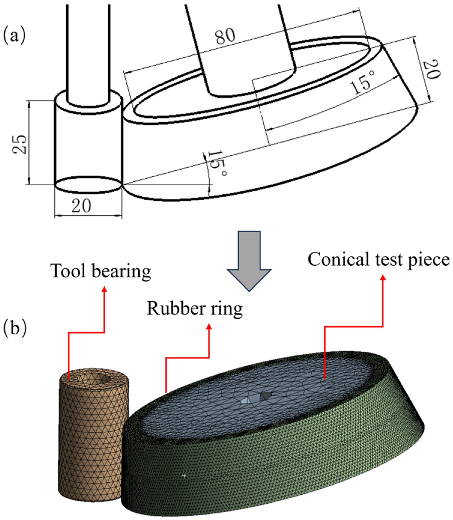
The milling principle of the conical test piece is shown in Figure 1(a). The end mill is milled along the shape of the conical test piece by a surface-driven method, and the tool axis is parallel to the side generatrix of the cone. In order to avoid the problems of direct cutting, such as consuming a large number of cutting samples and large tool wear, this paper uses rubber rings with different thicknesses to cover the conical surface of the conical test piece, as shown in Figure 1(b). The bearing of cutter mounted on the outer side of the tool rolls and squeezes the rubber ring. The deformation degree of the rubber material is used to simulate the cutting depth of the tool in the actual cutting process of the metal workpiece, and the three-dimensional force cutting load is applied to the five-axis machining center.
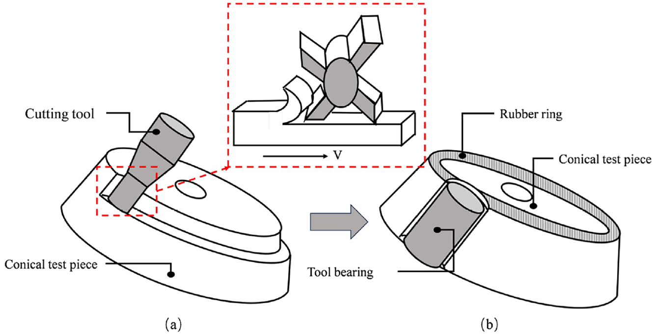
(a) Cutting principle of conical test piece and (b) improvement scheme.
Structure composition of multi-dimensional force tracking-loading simulator
The main body of the multi-dimensional force follow-up loading simulation device includes four parts: tool bearing, loading simulator, Kistler9139 dynamometer, and five-axis machining center workbench, as shown in Figure 2. Among them, the tool bearing sleeve is installed on the outer side of the tool, and the feed motion is carried by the machine tool spindle. The loading simulation device is composed of rubber ring, cone test piece, support piece, and installation bottom plate. The Kistker9139 dynamometer is connected to the computer, and Matlab, Origin, and other software are used to filter the cutting force signal, coordinate transformation and numerical calculation. The five-axis machining center workbench integrates two rotating axes, which can swing forward and backward around the A-axis from −90° to 90°, and rotate 360° freely around the C-axis.

Structure and working principle of multi-dimensional force tracking-loading simulator.
In order to simulate the actual cutting process of the five-axis machining center, the loading simulator is mounted on the Kistler9139 dynamometer, which is installed on the workbench of the five-axis machining center. The cutting force is generated under the interaction of the main motion of the spindle and the relative feed motion of the workbench. The simulated cutting process can be divided into two steps: the tool feed process and the cutting process. The tool bearing is first pressed downward along the direction perpendicular to the surface of the rubber ring to simulate the tool feed process. After reaching the specified feed rate, the outer surface of the rubber ring is rolled for one week to simulate the cutting process.
Multi-dimensional force tracking-loading model
Definition of geometric parameters and coordinate system
The cutting force model of the five-axis machining center is established by using the coordinate system transformation principle and the rigid body hypothesis theory. The coordinate system definition is shown in Figure 3(a). Taking the center of the tool bearing as the coordinate origin
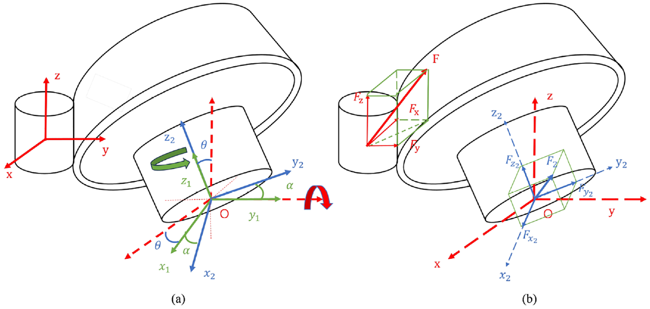
(a) Coordinate system definition of multi-dimensional force tracking-loading simulator and (b) force analysis.
According to the decomposition of the force, the force of the five-axis machining center is shown in Figure 3(b). The cutting force can be decomposed into tangential force
Establishment of multi-dimensional cutting force model
Since the tool bearing is connected to the spindle of the machine tool, the cutting force can be decomposed into the tangential force
where
The components

Similarly, the components of cutting force in
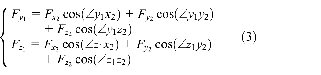
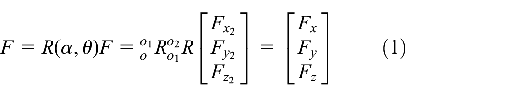
Then the matrix form of cutting force:

Since the rotation angle of the workpiece coordinate system
Then the pose matrix of the workpiece coordinate system

Similarly, the pose matrix of the intermediate coordinate system

Then the pose matrix of the workpiece coordinate system

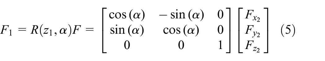
Substituting equation (8) into equation (1), the components of the

Simulation model establishment
Based on the simulation software Ansys, the geometric models of multi-dimensional force tracking-loading simulators with different rubber ring thicknesses were established respectively. As shown in Figure 4(a), it is the geometric model of the multi-dimensional force tracking-loading simulators with 2 mm rubber ring thickness. It is mainly composed of tool bearing, conical test piece, and rubber ring. The tool bearing presses the rubber ring along the conical test piece to simulate the multi-dimensional force tracking-loading process. According to International Standards ISO 10791-7:2020(E), the upper part of the bottom of the cone is a cone with a diameter of 80 mm, a thickness of 20 mm, a cone half vertex angle of 15°, and the bottom of the cone is inclined by 15°. Tool bearing diameter 20 mm, height 25 mm.
(a) Geometric model of 2 mm rubber ring multi-dimensional force tracking-loading simulator and (b) meshing.
In order to improve the accuracy of simulation calculation, the multi-layer structure is meshed by the structured method and the scanning method, and the local mesh of the rubber ring is encrypted. The multi-dimensional force servo loading simulation device is divided into 179,135 hexahedral elements, as shown in Figure 4(b).
In order to obtain the mechanical properties of the hyper-elastic rubber ring, the uniaxial compression test was carried out, and the measured stress-strain relationship is shown in Table 1. Because the rubber material has the characteristics of large elastic deformation and incompressibility, its mechanical properties show nonlinear elastic behavior, so the Neo-Hookean model is selected in Ansys software. The stress-strain relationship of uniaxial compression test is introduced into the model to characterize the nonlinear characteristics of rubber materials.
Strain-stress relationship of rubber material.

Design of multi-dimensional force tracking-loading experiment scheme
In order to verify the feasibility of the multi-dimensional force tracking-loading simulator, a loading experiment was carried out on a five-axis machining center. The multi-dimensional force tracking-loading experiment system is built as shown in Figure 5. The experimental equipment includes a five-axis machining center, a Kistler9139 dynamometer, a charge amplifier, and a laptop equipped with data acquisition and processing software. Before the multi-dimensional force tracking-loading experiment, the simulator needs to be leveled to ensure that the tool bearing is tangent to the side of the conical test piece. In order to obtain the dynamic cutting force, the Kistler9139 dynamometer is installed on the workbench of the five-axis machining center, and the loading simulator is installed on the Kistler9139 dynamometer. The tool bearing is connected with the spindle of the machining center. The program drives the spindle of the machining center to move along the conical test piece for 360°. The tool bearing rolls and presses the rubber ring on the surface of the conical test piece to a certain depth to complete the loading experiment. The cutting force between the tool bearing and the loading device is transmitted to the Kistler9139 dynamometer. The Kistler charge amplifier5080A amplifies the cutting force signal and collects it through the data acquisition system. Finally, the cutting force signal is filtered, the coordinate change and the numerical calculation is processed by using the computer with Matlab, Origin, and other software. The experimental parameters were designed by orthogonal test method.

Multi-dimensional force tracking-loading simulation experiment system.
According to the empirical formula of cutting force, the influence parameters of cutting force are mainly cutting depth, feed per tooth, and cutting speed. In this experiment, the rubber material on the surface of the conical test piece is pressed by the tool bearing, and the influence of the thickness of the rubber ring and the cutting depth on the cutting force is mainly considered. Therefore, according to the requirement that the comprehensive force of the spindle of a five-axis machining center does not exceed 1000 N, the multi-dimensional force tracking-loading experiment of 0.2, 0.4, and 0.5 mm cutting depth is carried out with different rubber ring thicknesses of 2, 3, 5, and 6 mm respectively. In order to eliminate the uncertainty in the experiment, each group of experiments was repeated three times.
Results and discussion
Analysis of experiment results
According to the above experiment process, the spindle speed is set to 1000 rpm, and the orthogonal loading experiment is carried out with the two main factors of cutting depth and rubber ring thickness. The experimental data are brought into the cutting force model for coordinate transformation, and the cutting force curve of each axis of the five-axis machining center is obtained. Taking 0.5 mm cutting depth as an example, the cutting force of each axis of the five-axis machining center is shown in Figure 6. It can be seen that the cutting force of the five-axis machining center in the x axis is cosine distribution, the cutting force in the y and z axes is sinusoidal distribution, and the cutting force in each axis decreases with the increase of the thickness of the rubber ring. From the changing x, y, z axial cutting force, it can be seen that the simulation device has a multi-dimensional loading capacity of three degrees of freedom. It can follow the actual cutting path of the five-axis machining center and apply three-dimensional cutting force load to verify the feasibility of the simulator. Compared with 3, 5, and 6 mm, when the thickness of the rubber ring is 2 mm, the cutting force in each axial direction is the largest, and there are obvious fluctuations at the peak and trough. The main reason for this phenomenon is that the cutting force is too large, which will lead to the lack of stability when the workbench is rotated to the limit angle position, resulting in the fluctuation of the axial cutting force when the thickness of the apron is 2 mm. Therefore, when the thickness of rubber ring is 2 mm, each axial cutting force fluctuates obviously at the peak and trough. As the axial cutting force decreases, each axial cutting force curve is very smooth when the thickness of rubber ring is 3, 5, and 6 mm, which provides a certain reference for the reliability test of CNC machine tools.
Five-axis machining center in the x, y, z axis direction force load experiment curve.
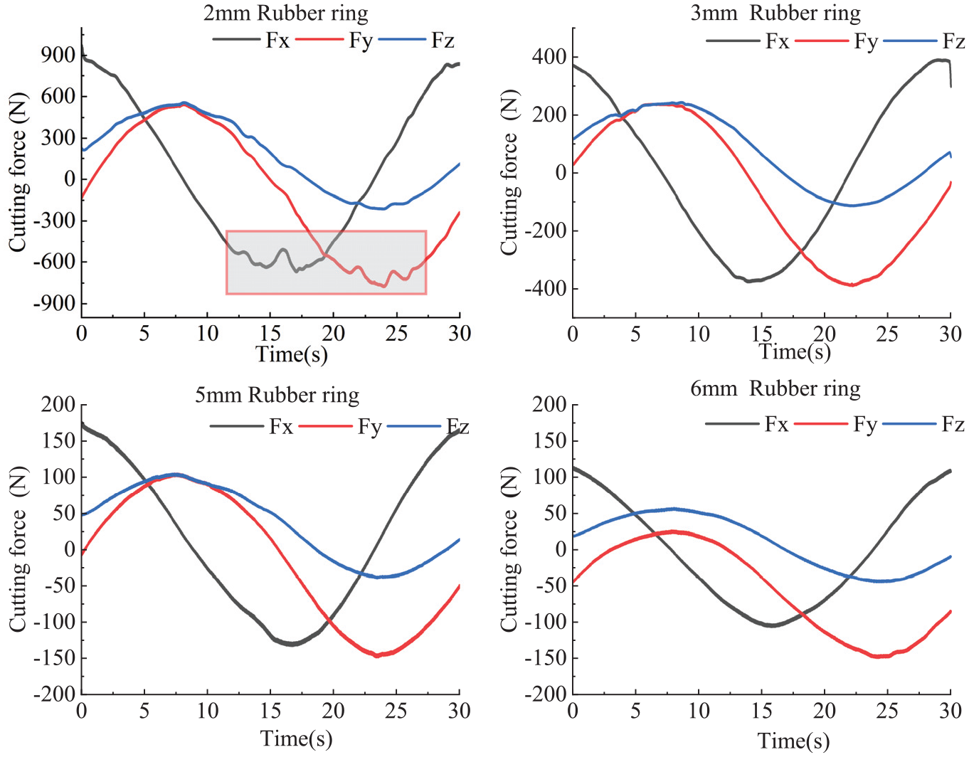
Through the vector synthesis of each axial cutting force, the comprehensive force of the five-axis machining center is shown in Figure 7. It can be seen that the comprehensive force of the five-axis machining center is negatively correlated with the thickness of the rubber ring and positively correlated with the cutting depth, and the comprehensive force has a large fluctuation. If the thickness of the rubber ring is too thin or too thick, it is easy to cause a large fluctuation of the comprehensive force. When the thickness of the rubber ring is 2 mm, the vibration of the five-axis machining center will also cause the fluctuation of the comprehensive force because the rubber ring is too thin, and the fluctuation range of the comprehensive force decreases with the decrease of the cutting depth. When the thickness of the rubber ring is 5 and 6 mm, with the increase of the cutting depth, the contact area between the tool bearing and the rubber ring increases, which makes the friction between the tool bearing and the rubber material increase. Finally, the high temperature in the contact area between the tool bearing and the rubber ring leads to the thermal softening of the material, which reduces the cutting force. When the comprehensive force decreases, the cutting heat generated by the processing decreases, so that the thermal softening effect is reduced, so the cutting force increases again, resulting in the fluctuation of the comprehensive force. 24 Through comprehensive comparative analysis, when the thickness of the rubber ring is 3 mm, the fluctuation of the comprehensive force of the machining center is the smallest, which is the best thickness for the reliability test of the five-axis machining center.

Comprehensive force experiment curve of five-axis machining center.
The comprehensive force obtained from the experiment is averaged, and the average value of the comprehensive force of the five-axis machining center is shown in Table 2. It can be seen that the average value of the comprehensive force is less than 1000 N when the thickness of the rubber ring of 2, 3, 5, and 6 mm is 0.5, 0.4, and 0.2 mm cutting depth, which meets the requirements of the five-axis machining center.
Multi-dimensional force tracking-loading experiment results.

Analysis of simulation results
Taking the same rubber ring thickness and cutting depth of the test for simulation, the cutting force of the cone specimen on each axis of the five-axis machining center is obtained. Taking 0.5 mm cutting depth as an example, the cutting force load of each axis of the five-axis machining center is analyzed, as shown in Figure 8. It can be seen that the cutting force load of the five-axis machining center in the x-axis direction is sinusoidal distribution, the force load in the y-axis direction tends to be stable, the cutting force load in the z-axis direction is cosine distribution, and the cutting force decreases with the increase of the thickness of the rubber ring. When the thickness of the rubber ring is 2 and 5 mm, the cutting force curve has burrs, and the fluctuation of the cutting force is obvious at the peak and trough. The main reason for the fluctuation of the cutting force curve and burrs is. The results show that the simulation model can simulate the three-dimensional dynamic force load of the five-axis machining center in the actual cutting process.
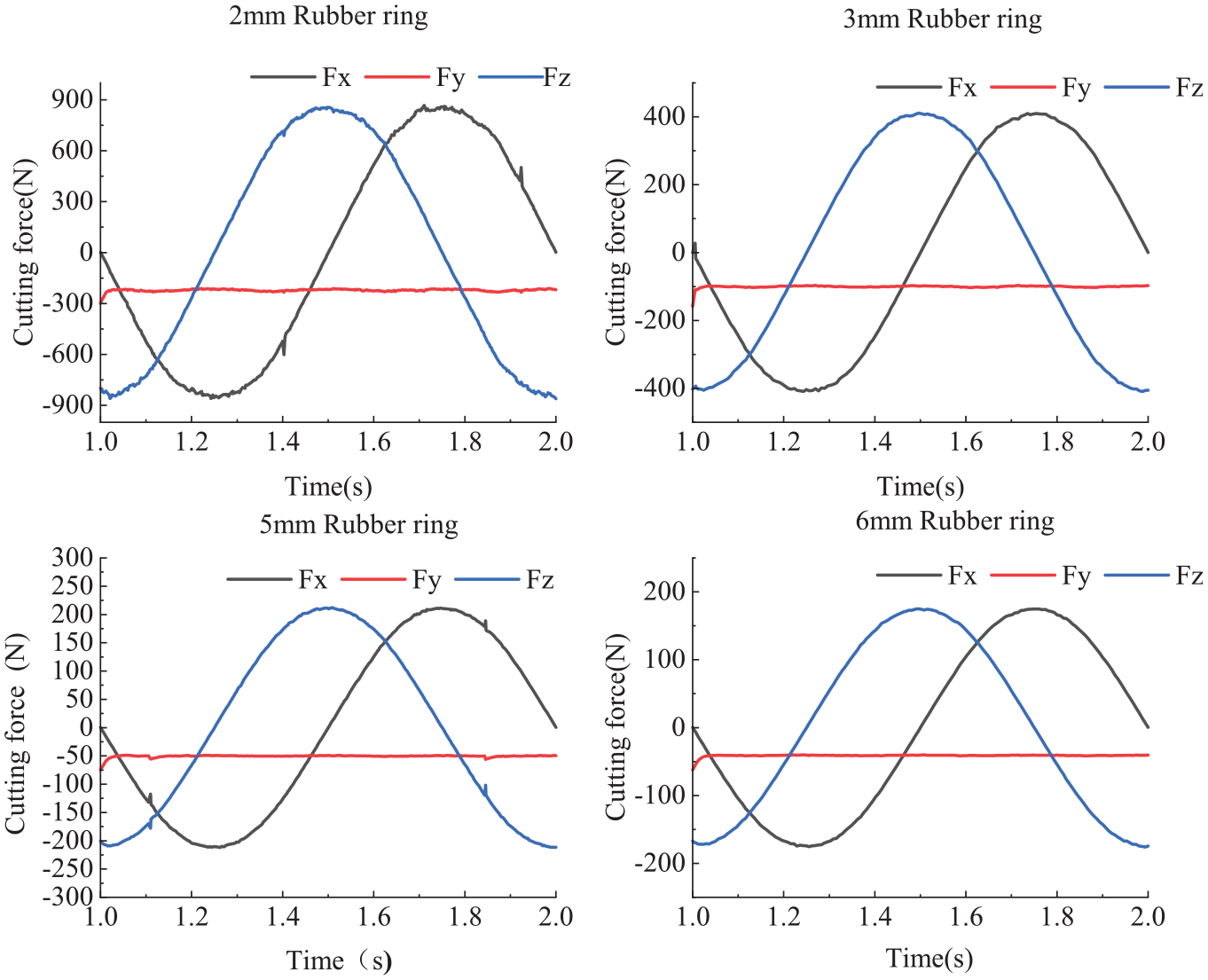
Five-axis machining center in x, y, z axial force load simulation curve.
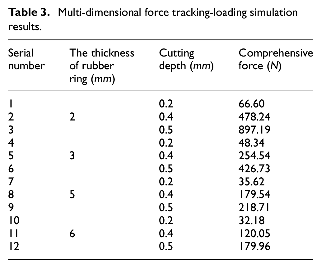
Through the vector synthesis of each axial cutting force, the comprehensive force change curve with different cutting depth and rubber ring thickness is obtained, as shown in Figure 9. The comprehensive force of the five-axis machining center increases with the increase of the cutting depth and decreases with the increase of the thickness of the rubber ring. The average comprehensive force obtained by averaging the simulation data is shown in Table 3. When the thickness of the rubber ring is 2 mm, the average comprehensive force of the five-axis machining center is the largest. As the cutting depth increases, the average comprehensive force increases from 66.6 to 897.19 N. When the thickness of the rubber ring is 6 mm, the average comprehensive force of the five-axis machining center is the smallest. As the cutting depth increases, the average comprehensive force increases from 32.18 to 179.96 N. Comprehensive analysis, 2, 3, 5, 6 mm rubber ring thickness in the case of 0.5, 0.4, 0.2 mm cutting depth, the average comprehensive force is less than 1000 N, meet the requirements of five-axis machining center, provide a reference for multi-dimensional force follow-up loading experiment.
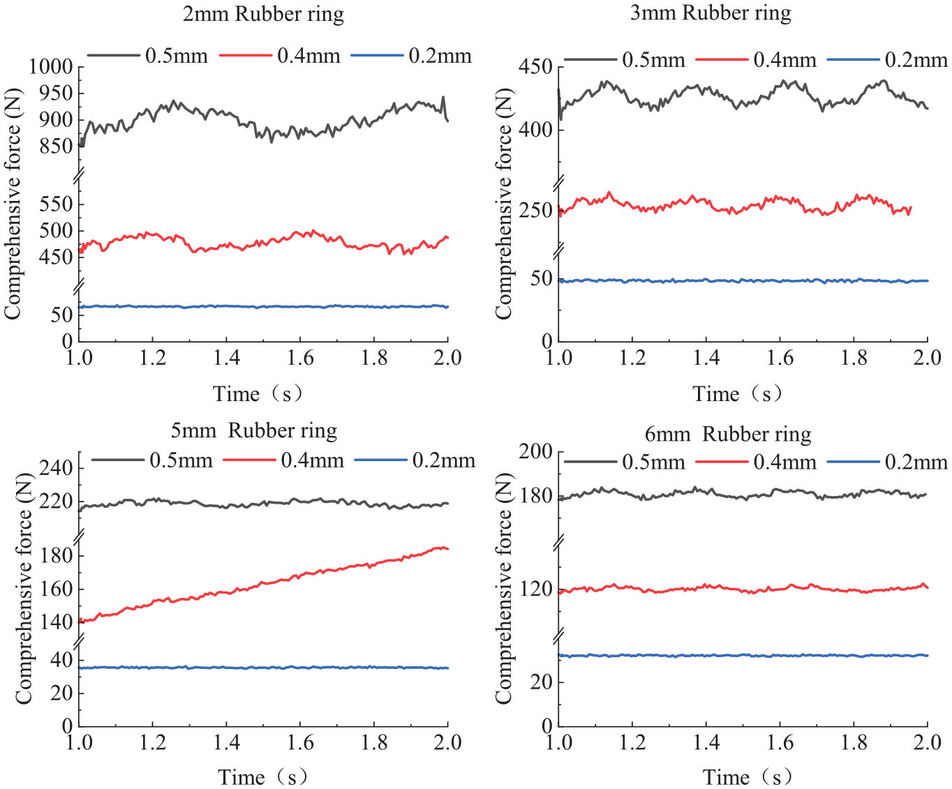
Comprehensive force simulation curve of five-axis machining center simulation curve.
Multi-dimensional force tracking-loading simulation results.
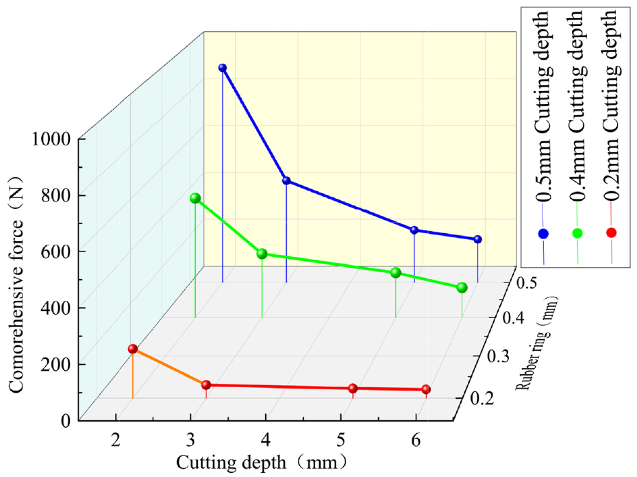
The average comprehensive force obtained from the simulation is fitted. Under different cutting depth, the average comprehensive force changes with the thickness of the rubber ring, as shown in Figure 10. It can be seen that the comprehensive force of the 2 mm 6 mm arbitrary rubber ring thickness model of the five-axis machining center at different cutting depth. When the cutting depth remains unchanged, the average comprehensive force decreases with the increase of the thickness of the rubber ring. When the thickness of the rubber ring increases from 2 to 3 mm, the average comprehensive force decreases significantly. Taking the cutting depth and the thickness of the rubber ring as the independent variables, and the comprehensive force as the dependent variable, the average comprehensive force curve is further fitted to obtain the three-dimensional surface diagram shown in Figure 11. It can be seen that the comprehensive force of the 2 mm 6 mm rubber ring thickness model of the five-axis machining center at any feed amount of 0.2 mm 0.5 mm. With the increase of cutting depth and the decrease of rubber ring thickness, the average comprehensive force shows an increasing trend. The maximum point is in the range of 2 mm rubber ring thickness and 0.5 mm cutting depth, and the maximum value is 773.3 N. The minimum point is in the range of 6 mm rubber ring thickness and 0.2 mm cutting depth, and the minimum value is 240.8 N.
The variation curve of the comprehensive force with the thickness of the rubber ring under different feed rates.

Curved surface diagram of feed rate-rubber ring thickness-comprehensive force.
Comparative analysis
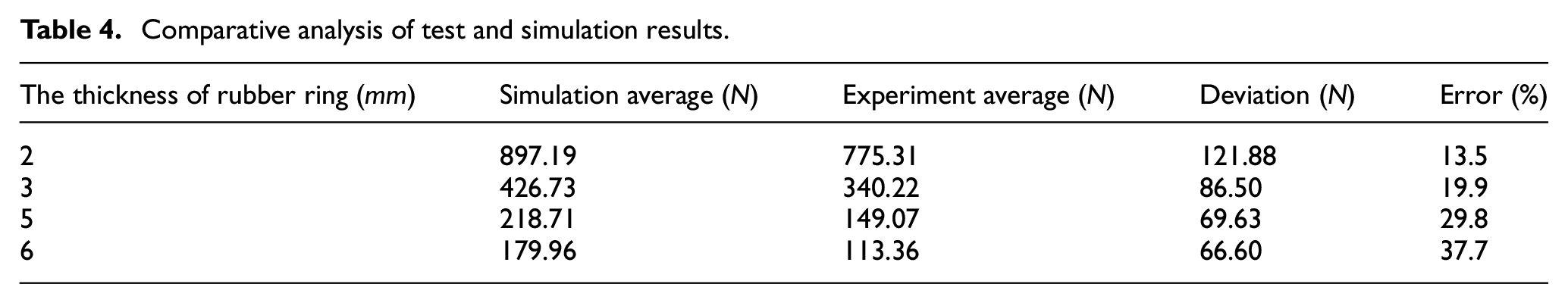
From the analysis of Section 5.2, it can be seen that the comprehensive force increases with the increase of cutting depth, and the larger the cutting depth, the more obvious the fluctuation of the comprehensive force. Therefore, the maximum cutting depth of 0.5 mm is used for cutting force simulation verification. The simulation comprehensive force and the test comprehensive force are averaged, and the average comprehensive force of the simulation and the test is shown in Table 4. It can be seen that the comprehensive force of the simulation is greater than the comprehensive force of the test. This is because the simulation analysis process adopts the transient dynamics analysis instead of the thermo-mechanical coupling analysis step, and the influence of the cutting temperature on the cutting force is neglected in the calculation and analysis25,26; at the same time, there is a direction error between the workpiece coordinate system and the dynamometer coordinate system, 27 and there is a charge drift in the dynamometer system, 28 which will also lead to a certain error between the experimental measurement value and the simulation result. The relative error of the average comprehensive force of the experiment and simulation is compared and analyzed, and the error range is 13.5% 37.7%. When the thickness of the rubber ring is 2, 3, and 5 mm, the relative error of the average comprehensive force of the experiment and simulation is 13.5%, 19.9%, and 29.8%, respectively, which is lower than 30%, and the relative error is small. It can provide reference for reliability test of CNC machine tool. For the thickness of 6 mm rubber ring, the relative error of the experiment and simulation average comprehensive force is 37.7%, and the relative error is large. It is proved that the simulation model can better simulate the cutting process of the five-axis machining center, and accurately predict the comprehensive force of the five-axis machining center when cutting the conical table specimen, which is of guiding significance for the optimization of the machining parameters of the machine tool reliability test.
Comparative analysis of test and simulation results.
As shown in Figure 12, when the cutting depth is 0.5 mm, the experiment value and simulation value of the comprehensive force on the spindle of the five-axis machining center change with time. It can be seen from the figure that the simulation comprehensive force is slightly larger than the test comprehensive force, and there is a certain fluctuation. When the thickness of rubber ring is 2, 3, 5, and 6 mm, the maximum relative errors between the simulated comprehensive force and the experimental comprehensive force are 331.69, 96.3, 125.53, and 120.26 N respectively. When the thickness of rubber ring is 3 mm, the waveform and amplitude of the experimental comprehensive force are the closest to those of the simulated comprehensive force, and the fluctuation of the comprehensive force is the smallest. Therefore, the thickness of 3 mm rubber ring can better simulate the cutting process of the five-axis machining center, and accurately predict the comprehensive force of the five-axis machining center when cutting the conical test piece, which is the best thickness for the reliability test of the five-axis machining center.
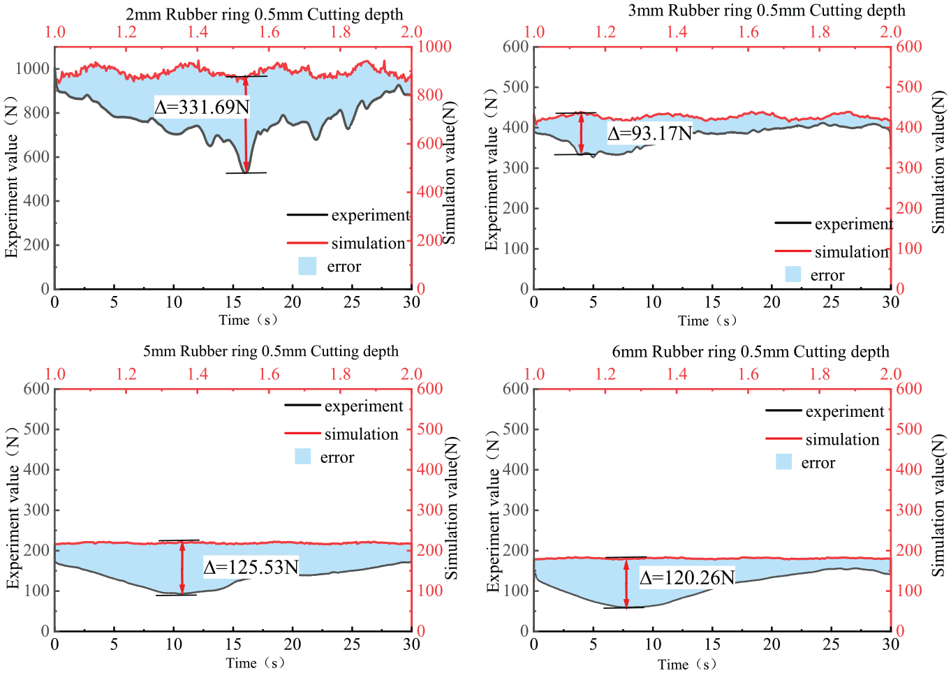
Comparison between the experiment and the simulation of the comprehensive force of the five-axis machining center.
Conclusions
In this paper, a multi-dimensional force tracking-loading simulator is proposed for the first time. Taking the conical test piece as the cutting object, carry out the multi-dimensional force tracking-loading simulations and experiments for the five-axis machining center. To investigate the influence of different rubber ring thickness and the feed rate on the cutting force during the machining process, which provides a novel loading method and reference for the reliability test of CNC machine tools.
Based on Ansys finite element simulation software, the super elastomer rubber models with different thicknesses are established. Through nonlinear dynamic simulation, the simulation results show that the comprehensive force of the five-axis machining center decreases with the increase of the thickness of the rubber ring and the decrease of the feed rate. In the case of 0.5, 0.4, 0.2 mm cutting depth, the average comprehensive force of the rubber ring thickness of 2, 3, 5, 6 mm is less than 1000 N, which meets the requirements of the five-axis machining.
The multi-dimensional force tracking-loading experiment is carried out on a five-axis machining center to verify the feasibility of the simulator. The simulator can apply multi-dimensional force tracking-loading to the five-axis machining center, which provides a recyclable and low-cost test method for the reliability test of CNC machine tool. The material loss caused by long-term cutting is avoided, and the complex problem of the control system of the existing machine tool reliability test device is solved, which is conducive to the engineering of reliability test.
Comparing the simulation and experimental data, the fluctuation of the comprehensive force on the five-axis machining center is the smallest when the thickness of the rubber ring is 3 mm, and the relative error between the experiment and the simulation comprehensive force is 19.8%. It has good loading accuracy and can accurately simulate the actual cutting of the five-axis machining center, which is the best thickness for the reliability loading experiment.
In this paper, a multi-dimensional force tracking-loading simulator is developed for the first time with a conical test piece. A preliminary research on multi-dimensional force tracking-loading experiment for five-axis machining center is carried out to form the research basis of cutting force simulation. This method can accurately simulate the cutting force of the actual cutting process of the five-axis machining center. At the same time, it has strong versatility and can be extended to the load simulation loading experiments of S-shape test piece and other non-standard test piece under actual machining conditions.
Footnotes
Handling Editor: Zuzana Murčinková
Author contributions
Conceptualization, W.J. and W.X.; methodology, S.J. and W.X.; validation, L.N., W.X., and W.J.; formal analysis, S.J.; investigation, Q.Z. and C.X.; resources, W.J.; data curation, L.H. and Y.X.; writing – original draft preparation, W.J., W.X., and S.J.; writing – review and editing, W.X., S.J., and W.J.; visualization, L.H.; supervision, S.J. All authors have read and agreed to the published version of the manuscript.
Declaration of conflicting interests
The author(s) declared no potential conflicts of interest with respect to the research, authorship, and/or publication of this article.
Funding
The author(s) disclosed receipt of the following financial support for the research, authorship, and/or publication of this article: This research was funded by 2019 Industrial Technology Basic Public Service Platform Project OF FUNDER grant number 0714EMTC000898.
Data availability
The data presented in this study are available on request from the corresponding author. The data are not publicly available to protect the information of key design parameters.