
Abstract
The Sommerfeld effect is a phenomenon in which a non-ideal prime mover fails to provide enough energy around the resonance speed in a vibration system, resulting in resonance capture and a nonlinear jump. This study discusses the successful techniques for attenuating the Sommerfeld effect in a vibration system with four degrees of freedom (DOFs) driven by a non-ideal induction motor. The kinetic equations of the system are derived using the Lagrange function. Additionally, the mean rotational speed and stability of a non-ideal motor are studied by energy balance and perturbation analysis method. Then, the relationship between electromagnetic torque and motor speed in the Sommerfeld effect is analyzed. The Sommerfeld effect exists near the natural frequencies (NFs) with electrical frequency increased or decreased. The main reason is that the gradually increasing mechanical load power of the vibrating system near the NFs contradicts the finite electromagnetic output power of the non-ideal induction motor. Moreover, the validity of the proposed methods is demonstrated through numerical analysis and simulation. The Sommerfeld effect can be effectively mitigated by appropriately increasing the damping coefficient, reducing the installation distance, and minimizing both the eccentric mass and eccentricity radius of the rotor.
Introduction
A mechanical device known as a prime mover provides prime power to mechanical systems, such as direct-current (DC) motors, induction machines and hydraulic motors,1–3 etc. The prime mover in a basic electromechanical system is typically idealized, and the relationship between mechanical components and energy loss is disregarded. 4 Nevertheless, the prime mover’s power cannot be unlimited in engineering applications. The dynamics of the electromechanical system and the saturated coupling of the actuator control the motor’s functioning, leading to non-ideal properties. 5 The existence of nonlinear jumps in motor speed and amplitude in a non-ideal vibrational system was first discovered by Arnold Sommerfeld in 1902 and named the Sommerfeld effect.6,7 In the vicinity of the resonant speed of the mechanical system, most energy of motor is shifted to vibrational foundation and only residual energy is effective in rotating rotor. As a result, the motor speed is limited and difficulty lifted, known as resonance capture. The trapped motor speed escapes from the resonance frequency through nonlinear hopping when the system’s power exceeds a certain threshold. Indeed, the Sommerfeld effect is characterized by resonance capture over a limited range in driving power followed by an abrupt liberation.8,9 Such typical nonlinear jumps in velocity and amplitude are commonly found in industrial dynamical systems.10–12 The inclusion of the Sommerfeld effect in the investigation of non-ideal vibrational systems is therefore imperative.
In recent decades, the theories of the Sommerfeld effect in nonlinear vibrational systems have been enriched by many scholars. González-Carbajal developed the concept of a quasi-static torque curve to characterize and predict the appearance of the Sommerfeld effect in vibrocompacting machines. 13 Besides, the Sommerfeld effect in dual-disk rotor cantilever beam driven by a non-ideal DC motor was revealed by Bisoi et al., through the multi-energy domain bond graph method. 14 The dynamics and Sommerfeld effect of a heavy rotor system which is coupled to a DC motor were explored by Bharti. In addition, the second kind of Sommerfeld effect was discussed in a model of rotors supported by noncircular rods and anisotropic foundation.15,16 For a 3-DOF shear build structure, Varanis et al. explored the characteristics of the Sommerfeld effect in the frequency domain through the synchronized wavelet transform method. 17 Sinha et al. investigated the Sommerfeld effect in a slotted cam machine driven by a DC motor with the bond graph models. 18
The control of the Sommerfeld effect has been studied by many authors since the Sommerfeld effect traps non-ideal motors in resonance capture and generates high amplitude vibrations. On the basis of the fuzzy Takagi-Sugeno model, Brogin et al. proposed a novel control strategy to suppress abnormal vibrations, due to the Sommerfeld effect, in a 3-DOF shear-wall. 19 To suppress the Sommerfeld effect in a flexible shaft-disk structure actuated by a DC machine with internal damping, Jha conceptualized an ideal proportional derivative controller via linearizing the current of active magnetic bearings. Besides, he presented the attenuation of the Sommerfeld effect in a discrete rotor system by adjusting the fractional order parameter in external damping.20,21 To suppress harmful vibration in geared rotor shaft drivelines excited by a DC machine, Sinha and Samantaray adjusted the structural parameters to effectively avoid the Sommerfeld effect. 22 Then, Castão et al. analyzed the inhibition process of the jump phenomena related to a non-ideal vibrational system excited by a DC motor with a nonlinear magnetic rheological damper. 23 Aiming at the inefficiency problem in the suppression process of the Sommerfeld effect, Samantaray discussed the efficiency of changing the foundation damping at a critical velocity in the nonlinear vibrational system with a single DOF. 24 To suppress the Sommerfeld effect in a magnetically levitated vibrational system excited by a non-ideal DC machine, Arbex et al. adopted passive and active control methods to decrease the amplitudes in resonance. 25
According to the aforementioned research, the DC machine is widely adopted by numerous scholars as a non-ideal prime mover due to its simplistic mathematical model. However, in comparison with the DC motor, the induction motor exhibits nonlinear characteristics and is intricately interconnected with multiple variables within large-scale mechanical systems. Bisoi et al. studied the Sommerfeld effect in a vibrational system with a single DOF driven by an induction motor, but neglected the nonlinear mechanical characteristics of the induction motor. 26 Werner investigated the control of oscillation in large induction machines installed on a flexible steel foundation, where the analysis of the Sommerfeld effect was absent in the study process. 27 Jiang et al. presented a cantilever beam vibration system driven by a non-ideal induction machine with an unbalanced rotor and the effect of unbalanced mass on the Sommerfeld effect was discussed. 28 Furthermore, Filimonikhin et al. proposed an experimental approach to explore the Sommerfeld effect in vibrational systems of pendulum, ball, or roller type driven by three-phase induction motors. 29
Non-ideal vibration systems excited by multiple motors exhibit not only the Sommerfeld effect but also another nonlinear phenomenon called synchronization. To investigate the self-synchronization and Sommerfeld effect of vibration systems actuated by two non-ideal DC machines, Sinha et al. utilized the multi-body dynamics simulation. 30 Djanan and Nbendjo explored the kinetic characteristics in a square plate vibration system driven by two DC motors with unbalanced rotors but failed to summarize the nonlinear phenomenon by the Sommerfeld effect. 31 Then, Kovriguine investigated the synchronization and Sommerfeld effect driven by two induction motors but lacked effective simulation analysis. 32 To further obtain the Sommerfeld effect under a synchronous state, a simply supported beam actuated by two unbalanced induction motors was presented by Kong. And proved the fact that a nonlinear jump in motor speed was the result of both the synchronous state and the Sommerfeld effect. 33 Zhang et al. analyzed the Sommerfeld effect in a double rigid frame vibrational structure excitation by two induction motors from the perspective of total load torque, and the jumping phenomenon of rotational speed was verified in the experiment. 34
In addition to the DC and induction motors, the typical nonlinear phenomena in vibrational systems driven by other types of non-ideal prime movers have been studied by several authors. To explain the abnormal phenomenon of dynamic response amplification of wind turbines, Lian et al. introduced the Sommerfeld effect into the study of steady responses under different loads. 35 By studying the simplified model of a car on an irregular road surface, Blekhman and Kremer analyzed the possibility that the engine speed was limited by the Sommerfeld effect in the process of power increase. 36 Wedig investigated the velocity jump phenomena of cars driving on roads by means of covariance equations, which can be ascribed as the Sommerfeld effect. 37
The Sommerfeld effect in vibration systems driven by non-ideal DC motors has been analyzed by many scholars, but only the vibrations in a single direction are studied due to the complexity of the calculation. Indeed, strong nonlinearities and complex couplings are typically exhibited in non-ideal vibration systems with multi-DOF. Therefore, in this paper, an induction motor as a non-ideal prime mover is introduced into a vibration system with four DOFs, and the effective methods of inhibiting the Sommerfeld effect are discussed. In Section “Simplified physical model and steady state analysis,” the dynamic model and the theory of the Sommerfeld effect in vibrational systems are concerned. In Section “Numerical analysis,” the basic characteristics and effect of structural parameters on the Sommerfeld effect are discussed by numerical analysis. In Section “Simulation analysis,” the effectiveness of the theoretical study is validated through simulation by establishing an electromechanical coupling model. Eventually, some conclusions are given in Section “Concluding remarks.”
Simplified physical model and steady state analysis
Simplified physical model
The simplified mechanical model of a four DOFs vibration system is presented in Figure 1(a), including horizontal vibration, vertical vibration, swing vibration, and rotor rotation motion. The rigid frame with mass m0 is supported by springs with stiffness coefficients k i and dampers with damping coefficients f i (i = x, y, ψ). Here, an eccentric rotor with mass m is driven by an induction motor which can be considered as a non-ideal power source providing limited energy. The rotation centers of the vibration system and the motor are O′ and O, respectively. Furthermore, the rotation angle and eccentricity radius of the rotor are denoted as φ and r, respectively. Parameter ψ is the swing angle of the rigid frame. In addition, the installation distance and installation angle of motors are defined as l and β, respectively.

Simplified model: (a) simplified mechanical model and (b) diagram of coordinate transformation.
On the basis of mechanical model, coordinate

The kinetic equations of the system are deduced by the Lagrange equation:

where, q = [x, y, ψ, φ]T and Q = [0, 0, 0, T
e
]T are generalized coordinate and generalized force matrix, respectively. The kinetic energy of the system is

where,

where, symbol C means the value of a physical quantity in the rotor equivalent to a physical quantity in the stator side; U
s
is the amplitude of phase voltage; R
r
and R
s
are the rotor and stator resistances, respectively; Lls = L
s
−L
m
and Llr = L
r
−L
m
are the stator leakage inductances and rotor leakage inductances, respectively; L
m
is the magnetic inductance;
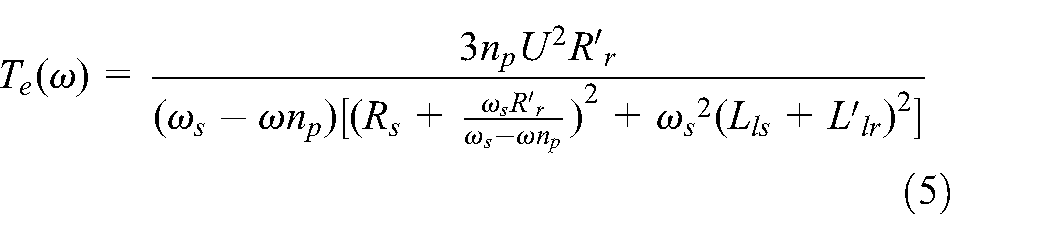
Then, the electromagnetic torque of induction motor can be derived by Te = P
m
/ω
m
, where
Steady state analysis
Since the motor speed fluctuation is much less than the average speed, the speed fluctuation can be ignored. When the system is in steady operation, the expressions

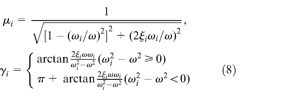
According to equation (6), the approximate steady responses of the system in x, y, and ψ DOF are deduced as:
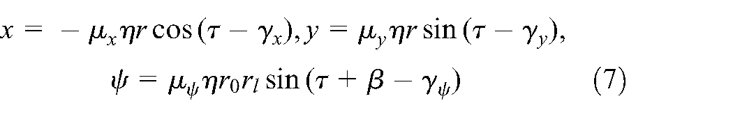
where:
To further explore the characteristics of the Sommerfeld effect, it is necessary to discuss the energetics in the vibrational system under the steady state. Thus, in view of the theory of electrical machinery, the electromagnetic output power from an induction motor over a time period is denoted as

According to the Rayleigh dissipation function D, the energy including the vibration of the vibrating body and the operation of the motor dissipated by the total mechanical load per cycle of rotation of the eccentric rotor can be derived as:

In vibration mechanics, the work done by the conserved force during a rotation period is zero. Thus, from the steady state energy equilibrium approach, the mechanical energy supplied by induction motor is balanced with the energy consumed by total mechanical load energy in a rotation period, namely Pm = P d . The energy balance equation for this vibration system can be formulated as follows:

Since equation (11) is a nonlinear higher-order transcendental function concerning ω, it proves very hard to obtain analytic answers directly. It needs to be calculated by numerical analysis method. Some potential solutions in equation (11) correspond to stable roots, while others are unstable. It can be noticed that a particular stable solution of this equation should be under the local minimum energy state. Therefore, it is necessary to propose a perturbation analysis method to analyze the stability of these solutions. When a positive perturbation is given to the motor velocity, the difference between the electromagnetic output energy of motor and the total energy dissipated can be determined. If this difference is negative, the total dissipated energy in the system proves greater than the input energy, which reduces the speed of the motor and returns it to the unperturbed state. The conditions satisfying the stable energy regime are then obtained as:

where:


where
Numerical analysis
In the previous discussion, the dynamics and Sommerfeld effect of the vibration system are analyzed based on theory. Then, the Sommerfeld effect is analyzed by revealing the steady motion of the vibration system through the numerical analysis method in this section. The essential parameters of the induction motor and rotor system are expressed in Table 1, the following representative values are considered: fy = 150 N· s/m, r = 0.10 m, m = 1 kg, and l = 0.20 m. Moreover, the NF ω x , ω y , and ω ψ of the vibration system are calculated as 55.81, 77.88, and 104.88 rad/s, respectively.
Representative parameters of the system.

Typical characteristics of Sommerfeld effect
In light of equations (11) and (12), the mechanical steady speed ω and stability coefficient H versus electrical frequency f
s
are depicted in Figure 2(a) and (b), respectively. The steady responses with x, y, and ψ DOF of the vibration system are presented in Figure 2(c) to (e). Notably, the steady speed curve is nonlinear, which differs from the linear curve derived from the function ω = 2
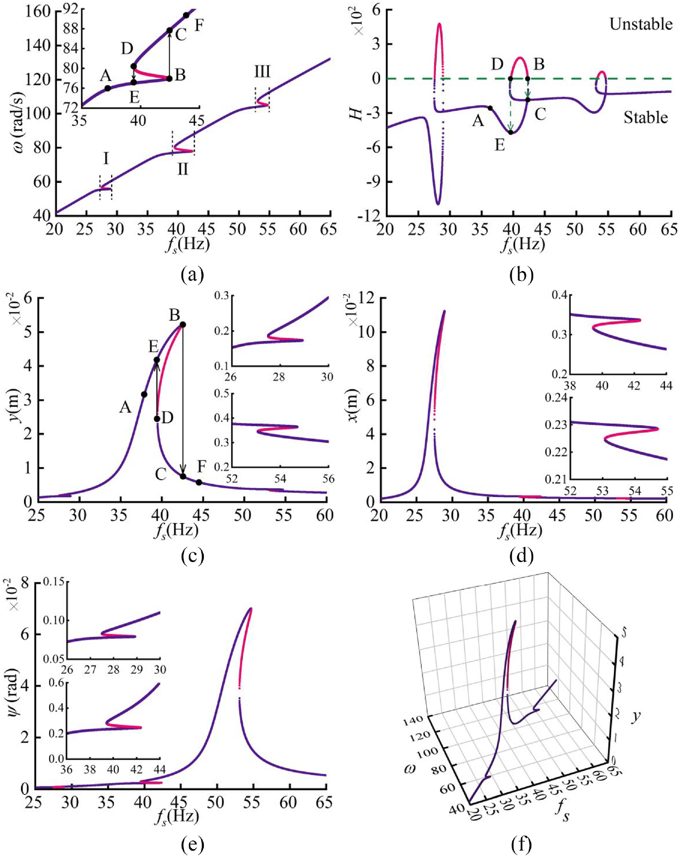
Frequency domain responses of the system with m = 1 kg, fy = 150 N·s/m, r = 0.10 m, and l = 0.20 m: (a) steady state motor speed, (b) stability coefficient, (c) amplitude of vertical vibration, (d) amplitude of horizontal vibration, (e) amplitude of swing vibration, and (f) y versus f s versus ω.
The typical characteristics of the Sommerfeld effect are revealed by focusing on the process of nonlinear jump (path A→E→B→C) in region II (39.45 Hz < f s < 42.38 Hz). During induction motor coast-up with gradually increasing electrical frequency in Figure 2(a), the motor speed and the vertical amplitude are almost increased linearly before point A. Whereas, when the motor speed approaches the critical point B, the increment of speed decreases, and the vertical amplitude rises still rapidly. This unusual phenomenon indicates that the motor speed seems limited near the resonance speed, which is known as resonance capture. Subsequently, when the frequency increases to jump point B (fs = 42.38 Hz, ωB = 77.94 rad/s, yB = 51.99 mm), the motor speed and the vertical amplitude suddenly shift from B to C (ωC=87.76 rad/s, yC = 7.78 mm). After point C, the motor speed extricates from resonance capture and restores to increase linearly. The vertical amplitude decreases continuously after passing the NF ω y . The nonlinear jump in motor speed is validated from the stability coefficient curve in Figure 2(b). The stability coefficient approaches zero infinitely at point B and jumps from point B to point C. Moreover, during the coast-down operation of the induction motor following the decreasing electrical frequency, there also exists a nonlinear jump in motor speed and amplitude (path C→D→E). Since the branch of the stability coefficient curve between point D to B is unstable, the motor speed and the vertical amplitude jump from D (fs = 39.45 Hz, ωD = 80.52 rad/s, yD = 24.14 mm) to E (ωE = 77.04 rad/s, yE = 42.17 mm) rather than from C to B. After crossing point E, the amplitude gradually weakens with the decrease in motor speed. In addition, similar nonlinear jumps in the motor speed and amplitude near NFs ω x and ω ψ exist in region I (27.50 Hz < f s < 28.92 Hz) and region III (53.08 Hz < f s < 54.71 Hz), respectively. To better visualize it, the three-dimensional plot between frequency f s , vertical amplitude y, and motor speed ω is depicted in Figure 2(f). Besides, the stability coefficient curve contains the unstable branches between the corresponding jump points. Remarkably, due to the vibrational coupling between each DOF, when there is a nonlinear jump in the amplitude of one DOF, there is also a small jump in the amplitude of the other DOF. In short, the nonlinear jumps of motor speed and amplitude near the NF are the typical phenomenon of the Sommerfeld effect.
Subsequently, the nonlinear jump phenomenon of the Sommerfeld effect has been analyzed from the view of energy balance. The electromagnetic output power (P m ) and the total mechanical load power (P d ) at various frequencies are depicted in Figure 3. Such as fs = 32 Hz in Figure 3(a), there exists one intersection point between P m and P d , which indicates the P m can both satisfy the energy required to rotate the motor and the load energy consumption. Therefore, the vibration system reaches energy equilibrium and the motor speed corresponds to the abscissa of the intersection point. However, due to the vibrational system having high amplitude in the resonance, three nonlinear cusps exist near the three NFs of P d , which results in an increase in the energy consumed by the mechanical load. As fs = 28 or 54 Hz, multiple solutions of speed exist with three intersection points between P m and P d . The fact that the increasing mechanical load power of the vibrating system contradicts the finite electromagnetic output power of the non-ideal induction motor leads to the inability of electromagnetic output power to support the motor rotation. Therewith, as fs = 39.45 or 42.38 Hz in Figure 3(b), two intersection points between P m and P d exist near the NF ω y , which means the vibration system falls into resonance capture in the range of these two frequencies. Then, when the electrical frequency is 42.38 Hz, increasing again the frequency will cause the vibrational system to exceed the resonance region. Therefore, as the total mechanical load power is reduced, the induction motor can allocate more energy to satisfy the motor rotation, resulting in the speed return to a linear increase. The energy balance relationship between P m and P d around ω x and ω ψ can be obtained by similar analysis methods. The analysis above confirms again the generation process of the Sommerfeld effect from the perspective of energy.

Electromagnetic output power P m and total mechanical load power P d : (a) P m at various electrical frequencies and (b) P m and P d near NF ω y .
The electromagnetic output power (P
m
) is mainly related to electromagnetic torque (T
e
). Thus, based on equation (5), the characteristic curves of the induction motor are plotted in Figure 4 and the operating points A to F in Figure 2(a) to (c) are marked. The characteristic curve greatly affected by electrical frequency reflects the nonlinear relationship between electromagnetic torque versus the motor speed, and
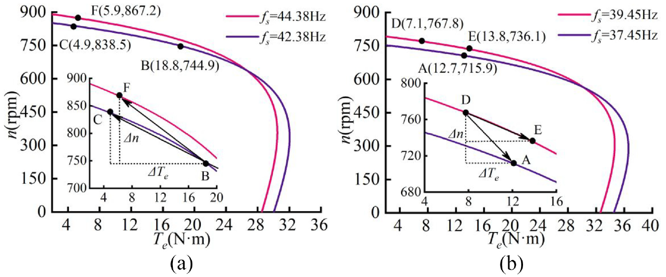
Characteristic curve of induction motor: (a) the process of increasing frequency and (b) the process of decreasing frequency.
The influence of structural parameters
After analyzing the basic characteristics of the Sommerfeld effect, the effect of different structural parameters on the dynamic characteristics of the vibration system is crucial for the investigation of suppressing the Sommerfeld effect in engineering applications. Other structural characteristics are held constant when analyzing the effect of a certain structural parameter on the Sommerfeld effect.
The impacts of different damping coefficients f y on the Sommerfeld effect of the vibration system are explored in Figure 5. What stands out in Figure 5(a) is that the greater the damping coefficient, the smaller the frequency of the speed jump point. In other words, the non-ideal motor can smoothly cross the resonance point while being less affected by resonance capture at a high damping coefficient. When f y reduces to 100 N·s/m, the motor speed is trapped by resonance at the resonant speed NF ω y . Compared to the high-damping system, it is difficult for the motor to cross the resonance region in the low-damping system. The stability curve in Figure 5(b) indicates that the larger damping coefficient is favorable to the stability in speed. Furthermore, from the amplitude-frequency curve in Figure 5(c), the nonlinearity of vibration is stronger with smaller damping. Since the motor speed makes it difficult to pass through the resonance point timely when fy = 100 N·s/m, the amplitude of the vibration system remains in the larger values. The influence of damping on the Sommerfeld effect can be revealed by the perspective of energy in Figure 5(d). The lower the damping coefficient, the greater the threshold of P d , which means that the range of electrical frequency becomes wider as multiple intersection points between P m and P d can be found. As a result, the motor is difficult to allocate enough energy for the velocity to cross the resonance point due to the sharp vibrations. In conclusion, the Sommerfeld effect of the vibrational system can be suppressed by increasing damping appropriately. Through employing the same method above, the effect of the damping coefficient in x or ψ directions on the Sommerfeld effect can be obtained, respectively.

Frequency domain responses of the system at different damping coefficient: (a) steady state motor speed, (b) stability coefficient, (c) amplitude of vertical vibration, and (d) P m and P d .
Next, the effect of different installation distance l on the Sommerfeld effect is analyzed in Figure 6. The results of steady motor speed and stability coefficient, as shown in Figure 6(a) and (b), indicate that the installation distance mainly affects the swing vibration of the system. As the installation distance decreases, the nonlinear region in the motor speed becomes smaller and more conducive to stability. In addition, through contrast swing vibration amplitude under different installation distances in Figure 6(c), it can be perceived that a positive correlation is found between installation distance and the nonlinearity of the amplitude-frequency curve. Since the motor speed is trapped in resonance capture as l = 0.30 m, the swing amplitude of the vibration system proves always large in the range f s > 55 Hz. The non-ideal motor is more difficult to pass through the resonance region at a shorter installation distance. The energy balance of the vibration system in Figure 6(d) also well describes the Sommerfeld effect in variation of installation distance. Due to the contradiction between the increasing dissipated energy and the finite mechanical output with increasing installation distance, sufficient energy is not easily obtained to maintain the stable operation of the motor. Thus, the range of frequency leading to the existence of multiple solutions for the speed becomes wider. Conversely, as the installation distance decreases, the threshold of P d reduces accordingly and the operating frequency of induction motor leisurely exceeds the NF ω ψ . In short, the swing direction of the system is mainly affected by installation distance of the motor, and the Sommerfeld effect can be suppressed by appropriately shortening the installation distance, which makes the vibration system easily get rid of the resonance capture.

Frequency domain responses of the system at different installation distance: (a) steady state motor speed, (b) stability coefficient, (c) amplitude of swing vibration, and (d) P m and P d .
Then, the Sommerfeld effect with different eccentric mass m is analyzed in Figure 7. From Figure 7(a) and (b), with the enhancement of the eccentric mass, the range of multiple and instability solutions of speed becomes wider. Most striking is that as eccentric mass enhances to 1.25 kg, the non-ideal motor may fail to pass through the resonance region. However, the motor speed can be increased almost linearly as eccentric mass reduces to 0.75 kg. In addition, the larger and nonlinear amplitude in vertical direction are appeared with enhancing eccentric mass in Figure 7(c). Besides, the energy curves of P m and P d are depicted in Figure 7(d) as the electrical frequency of P m is fs = 54 Hz. Evidently, the maximum of nonlinear cusps of the P d near the three NFs increases with the enhancement of the eccentric mass. Thus, the range of frequency which leads to the existence of multiple solutions in speed becomes wider. There are five points of intersection between P m and P d curves when eccentric mass is 1.25 kg, and two of which are near the NF ω y . This indicates that the motor energy at this time is not enough to support the motor crossing the NF ω y . Conversely, when eccentric mass is 0.75 kg, the dissipation energy of vibration system is greatly cut down. The mechanical output can maintain the vibration and motor rotation stably with excitation of a small eccentric mass. Therefore, the vibrational system excited by non-ideal motor is unsuitable with a large eccentric block mass. To suppress the Sommerfeld effect in engineering applications, the mass of eccentric block should be appropriately reduced.

Frequency domain responses of the system at different eccentric mass: (a) steady state motor speed, (b) stability coefficient, (c) amplitude of vertical vibration, and (d) P m and P d .
In Figure 8, the Sommerfeld effect in different eccentricity radius r of the block is discussed. From Figure 8(a) and (b), the greater the eccentricity, the stronger the nonlinearity in the motor speed. When r = 0.15 m, there are seven possibilities of frequency in motors near the NF ω ψ because the operating frequency of the non-ideal motor with a large eccentricity radius makes it difficult to climb over the NF ω x . While when eccentricity decreases to 0.05 m, the motor speed can be increased almost linearly. Besides, the nonlinear region in the motor speed becomes smaller and more favorable for stability. Such as amplitude of horizontal vibration with different eccentricity radii in Figure 8(c), the nonlinear characteristics of amplitudes increase with the increase of eccentricity radius. The corresponding energy curves of P m and P d are depicted in Figure 8(d) where the f s of P m equals to 41 Hz. Obviously, there are five points of intersection between P m and P d curves when eccentricity increases to 0.15 m, two of which are near the NF ω x . On account of energy imbalance, the operating frequency of motor cannot exceed the NF ω x . When eccentricity decreases to 0.05 m, the dissipative energy of vibration system is greatly reduced. As a result, the mechanical output can sustain the vibration and the operation of motor in a stable manner. In conclusion, the power of non-ideal motor is insufficient to support the operation of motor with a larger eccentricity radius, causing the motor to fall into resonance capture. To suppress the Sommerfeld effect and obtain a stable speed of non-ideal motor, the eccentricity radius should be reduced appropriately.
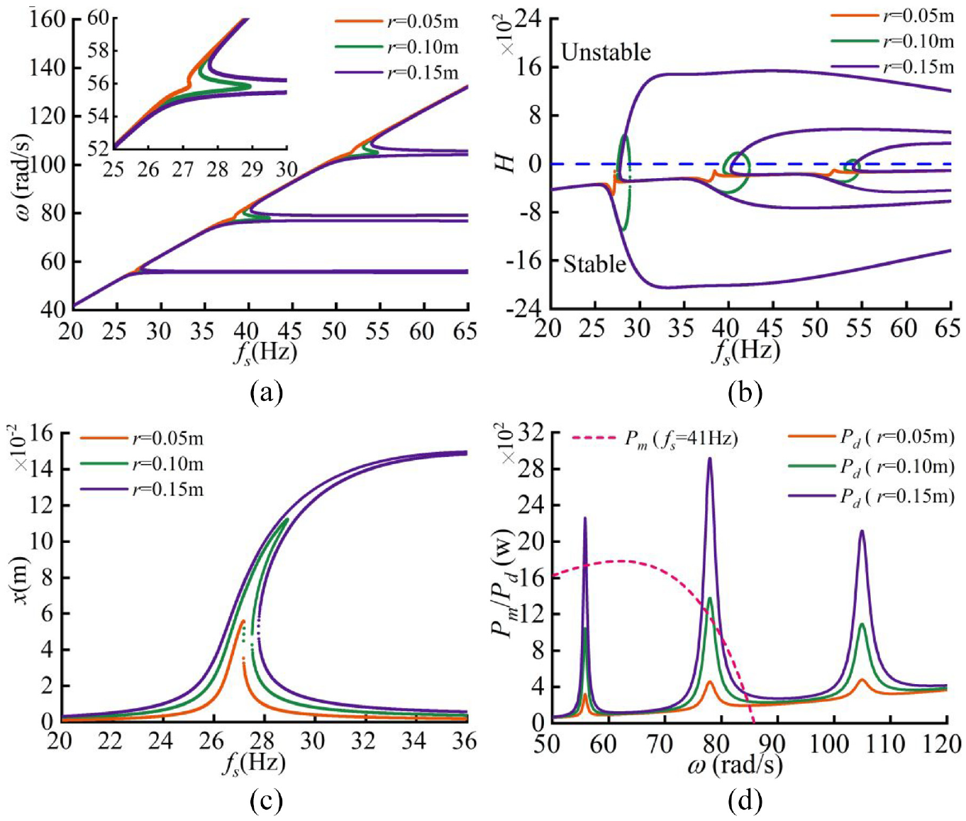
Frequency domain responses of the system at different eccentricity radius: (a) steady state motor speed, (b) stability coefficient, (c) amplitude of horizontal vibration, and (d) P m and P d .
Simulation analysis
The characteristics of the Sommerfeld effect have been examined in the previous sections through theoretical and numerical analysis. Additionally, the effect of various structural parameters, including damping coefficient, installation distance, eccentric mass, and eccentricity radius, on the dynamic responses of the system has been discussed. In this section, computer simulations are necessary to demonstrate the accuracy of the proposed theoretical approach and to elucidate effective methods to attenuate the Sommerfeld effect. As shown in Figure 9, a Matlab/Simulink-based electromechanical coupling model of the system is developed according to equation (3), and the Runge-Kutta algorithm is utilized to dynamically simulate the system. The speed of the induction motor is controlled by the open-loop frequency conversion speed control method. The Sommerfeld effect of the system is analyzed by increasing or decreasing the electrical frequency f s in the range of 20–65 Hz with intervals of 0.01 Hz. Based on the parameters in Table 1, the structural parameters of the system are chosen as identical in Section “Typical characteristics of Sommerfeld effect.”
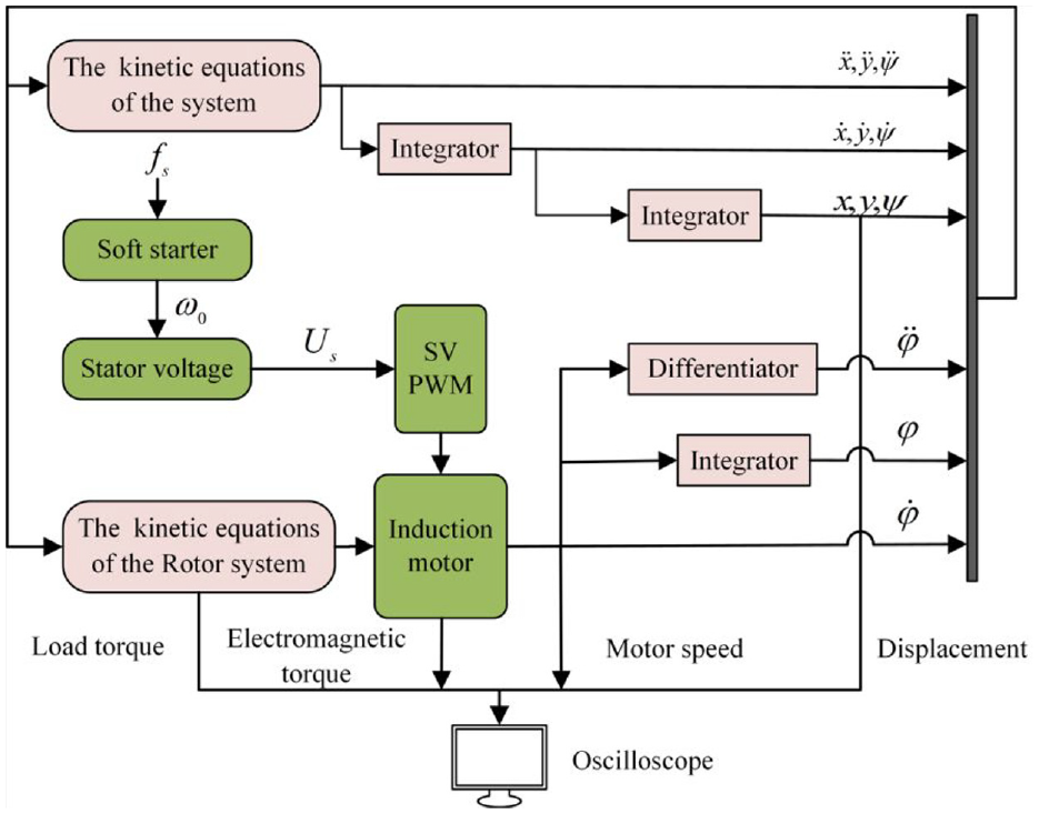
Simulation model.
Dynamic characteristics with increasing frequency
To verify the Sommerfeld effect during increasing frequency in Figure 2(a) (path B→F), the steady responses of the vibration system as electrical frequency f s increases from 42.38 to 44.38 Hz are displayed in Figure 10. The motor speed and vertical amplitude increase rapidly at fs = 42.38 Hz and eventually stabilize at 77.61 rad/s and 52.75 mm, respectively. The motor speed turns out to be difficult to exceed the resonance speed, and the vertical amplitude keeps increasing, namely the resonance capture. When f s raises 2 Hz at 10 s, the motor speed and displacement of the system significantly fluctuate due to the abrupt frequency variation. After 3 s, the motor speed stabilizes at 89.01 rad/s, while the vertical amplitude decreases to 7.28 mm. In this case, the vibration system overcomes resonance capture and exhibits a jumping process in both speed and amplitude. The electromagnetic torque of the induction motor and load torque of the system are illustrated in Figure 10(c). Due to the reduction of load consumption, the mean electromagnetic torque of the motor is reduced from 18.9 to 5.7 N m, which coincides with the numerical analysis in Figure 4(a). Moreover, the range of torque fluctuations decreases after passing the NF ω y . The fluctuation range of motor speed is small when the system under stable, which justifies the theory in Section “Steady state analysis” that neglects the velocity fluctuations. Finally, the stable motion trajectories at the barycenter of the vibrational system are presented in Figure 10(d), and the shape of the elliptic trajectory is obviously changed. In short, the essential features of the Sommerfeld effect are implemented by simulation and the theoretical analysis has been validated.

Dynamic characteristics with the frequency changed from 42.38 to 44.38 Hz: (a) motor speed, (b) vertical displacement, (c) electromagnetic torque and load torque, and (d) trajectory of motion.
Dynamic characteristics with decreasing frequency
The Sommerfeld effect exists not only in the frequency increase process but also in the frequency decrease process according to the previous discussion. Hence, the dynamic characteristics as electrical frequency decrease from 39.45 to 37.45 Hz in Figure 11 are utilized to verify the nonlinear jump phenomenon in Figure 2(a) (path D→A). When fs = 39.45 Hz, the motor speed increases rapidly during startup and eventually stabilizes at 80.83 rad/s in Figure 10(a). Interestingly, the motor speed at fs = 39.45 Hz is higher than fs = 42.38 Hz in Figure 10(a). The reason is that the motor speed has multiple solutions in region II of Figure 2(a). In the same frequency region, the corresponding speed of segment C→D is higher than B→E. Thus, the simulation results confirm again the nonlinear characteristics of the motor speed near the resonance speed. When f s suddenly decreases to 37.45 Hz, the motor speed jumps directly from 80.78 to 76.68 rad/s rather than decreases linearly. Besides, the vertical amplitude jumps from 21.76 to 42.17 mm in Figure 11(b). The fundamental characteristic of the Sommerfeld effect is the nonlinear jump in motor speed and of displacement, which reconfirms the precision of theoretical analysis. The electromagnetic torque of induction motor and the load torque of the system are depicted in Figure 10(c). Fluctuations in the electromagnetic torque and load torque increase with decreasing f s due to the rise in the vertical displacement. Meanwhile, the mean electromagnetic torque value rises from 6.9 to 13.1 N m, with discrepancies that fall within an acceptable range compared to the theoretical analysis in Figure 4(b). Finally, the stable motion trajectories at the mass center of the system are outlined in Figure 11(d). Due to the Sommerfeld effect, the elliptical trajectory suddenly changes.

Dynamic characteristics with the frequency changed from 39.45 to 37.45 Hz: (a) motor speed, (b) vertical displacement, (c) electromagnetic torque and load torque, and (d) trajectory of motion.
Dynamic characteristics with different structural parameter
The dynamic characteristics under different damping coefficients f y with the electrical frequency changes from 42.38 to 44.38 Hz are shown in Figure 12. The typical phenomenon of the Sommerfeld effect, when the damping coefficients fy = 150 N·s/m, have been thoroughly explained in Section “Dynamic characteristics with increasing frequency.” When fy = 100 N·s/m, as the frequency increases, the motor speed remains locked around 77.07 rad/s. Besides, the vertical amplitude increases from 62.48 to 72.37 mm, which indicates that the vibration system is trapped in resonance capture. Increasing f y to 200 N·s/m, the motor speed increases from 85.53 to 89.79 rad/s and the vertical amplitude slightly drops from 1.39 to 1.02 mm. Apparently, the speed and amplitude of the vibration system vary linearly under these parameters, implying the absence of the Sommerfeld effect. The simulation analyses are consistent with the results in Figure 5. Therefore, the Sommerfeld effect can be effectively suppressed by appropriately enhancing the damping coefficient.

Dynamic characteristics with different damping coefficient: (a) motor speed and (b) vertical displacement.
Following a change in electrical frequency from 54.71 to 56.71 Hz, the dynamic characteristics of system under various installation distances are discussed in Figure 13. When l = 0.20 m, the motor speed enhances from 104.17 to 114.82 rad/s, and the swing amplitude decreases from 6.59 × 10⁻² to 1.16 × 10⁻² rad, which manifests the existence of the Sommerfeld effect near the NF ω ψ . As l = 0.30 m, the motor speed always remains around 104.25 rad/s though f s changes. Moreover, the swing amplitude continues to increase. In this way, the vibration system is trapped in resonance capture for a large installation distance. By contrast, when l = 0.10 m, there exists a linear increase in motor speed from 111.06 to 115.03 rad/s and a decrease in swing displacement amplitude from 0.87 to 0.59 rad. Therefore, decreasing installation distance allows the vibration system to escape resonance capture effectively. These simulation analyses are in good agreement with the numerical analysis in Figure 6, which confirms that attenuating the Sommerfeld effect can be achieved by reducing the installation distance.

Dynamic characteristics with different installation distance: (a) motor speed and (b) swing displacement.
Therewith, as f s changes from 42.38 to 44.38 Hz, the dynamic characteristics of the system with various eccentric mass m are compared in Figure 14. The typical Sommerfeld effect of the vibrational system when m = 1.00 kg has been explained in Section “Dynamic characteristics with increasing frequency.” When m = 1.25 kg, although f s increases, the motor speed is locked at 77.21 rad/s and the vertical amplitude is always large, which suggests that the vibration system is trapped in resonance capture at a large eccentric mass. Conversely, as m = 0.75 kg, the motor speed increases linearly from 85.85 to 89.76 rad/s and the vertical amplitude decreases slightly from 0.69 to 0.47 mm. These simulation analyses are consistent with the numerical analysis in Figure 7. It has been confirmed that a proper reduction of the eccentricity mass can weaken the Sommerfeld effect in vibration systems.

Dynamic characteristics with different eccentric mass: (a) motor speed and (b) vertical displacement.
In Figure 15, the impacts of the electrical frequency changes from 28.92 to 29.92 Hz on dynamic characteristics with various eccentricity radius r are presented. The results show that when r = 0.10 m, increasing the frequency leads to a sudden jump in motor speed from 55.68 to 62.58 rad/s and a decrease in horizontal displacement amplitude from 10.08 to 1.17 mm, which confirms the existence of Sommerfeld effect near the NF ω x . However, when r = 0.15 m, the operating frequency of motor exceeding the NF ω x is difficult by increasing electrical frequency. The vibration system is trapped in a resonance state, and the horizontal amplitude is always great. On the contrary, when eccentricity r = 0.05 m, a linear increase can be observed in motor speed from 60.42 to 62.54 rad/s, and the horizontal amplitude varies from 0.65 to 0.55 mm. The simulation results agree with the numerical analysis in Figure 8. Therefore, decreasing the eccentricity radius can reduce the Sommerfeld effect of the vibrational system.

Dynamic characteristics with different eccentricity: (a) motor speed and (b) horizontal displacement.
Concluding remarks
The Sommerfeld effect in the vibrational system with four DOFs excited by a non-ideal induction motor is concerned. The kinetic equations of the system are derived from the Lagrange function. Additionally, the mean rotational speed and stability of a non-ideal motor are studied by the energy equilibrium approach and perturbation analysis method. Then, the validity of the proposed approach is demonstrated through numerical analysis and simulation. A summary of several significant findings is provided below:
The Sommerfeld effect exists around the NFs in the system. The system amplitude and motor speed jump nonlinearly as the electrical frequency approaches the NF in a rising or decreasing manner.
The reasons for the Sommerfeld effect are explained by the energy equilibrium approach and the mechanical characteristics of the induction motor. The progressively increasing mechanical load energy of the vibrating system contradicts the finite electromagnetic output energy of the non-ideal induction motor, which results in an inability of the electromagnetic output to support the rotation of the motor and to generate nonlinear jumps. As the electrical frequency increases, the electromagnetic torque decreases to reduce the energy consumption and enhance the motor speed. In turn, as the electrical frequency reduces, the induction motor increases the electromagnetic torque to meet the energy consumption and reduces the motor speed.
To suppress the Sommerfeld effect of vibrational systems in engineering applications, the influence of various structural parameters on the dynamic characteristics is further explored. From numerical analysis and simulation verification, it can be concluded that appropriately increasing the damping coefficient or reducing the installation distance of the motor is effective for attenuating the Sommerfeld effect. Besides, reducing the eccentric mass and eccentricity radius of the rotor allows the vibration system to pass smoothly through the resonance speed.
Footnotes
Handling Editor: Sharmili Pandian
Declaration of conflicting interests
The author(s) declared no potential conflicts of interest with respect to the research, authorship, and/or publication of this article.
Funding
The author(s) disclosed receipt of the following financial support for the research, authorship, and/or publication of this article: This work was supported by the Sichuan special equipment inspection research Institute research project(SCTJ-2023-YN01).