
Abstract
This paper introduced a hierarchical control strategy for direct yaw moment (DYC) to enhance the handling and stability of distributed drive electric vehicles (DDEVs) at medium to high speeds. The upper controller entailed a speed-following PI controller and an adaptive fuzzy linear quadratic regulator (AFLQR) controller, with the control objectives centered on reducing the absolute value of the sideslip angle and tracking the desired yaw rate. The proposed approach utilizes a fuzzy logic-based AFLQR controller, which could dynamically adjust the weighting parameters for sideslip angle and yaw rate in response to the vehicle speed and sideslip angle, offering better adaptability to varying driving conditions. At the lower control level, a tire-dynamic-load-based torque distribution method was applied. The control strategy’s efficacy was demonstrated through co-simulation involving CarSim and Simulink. This evaluation compared AFLQR control against non-yaw control, conventional LQR control and sliding mode control (SMC), focusing on handling and stability during sinusoidal steering wheel input test and double lane change maneuver. Results highlight that AFLQR reduces the sideslip angle by 7.88% and the yaw rate error by 84.29% compared to LQR, enhancing vehicle handling and stability. Lastly, a hardware-in-the-loop (HIL) experiment verified the control strategy’s validity.
Keywords
Introduction
Distributed drive electric vehicles (DDEVs) use in-wheel or wheel-side motors for propulsion. Unlike centralized drive vehicles, DDEVs streamline the transmission chain, enhancing efficiency and enabling yaw moment control for improved stability.1,2 DDEVs offer an ideal platform for exploring electric vehicle control tech and dynamic performance. This fuels the evolution of intelligent full-wire control for vehicle chassis and future electric vehicle (EV) advancements.3,4 However, while the distributed electric drive boosts propulsion versatility, torque allocation and managing multiple drive units heighten system complexity. The torque distribution strategy notably affects economy, handling, and high-speed stability. Thus, a reliable direct yaw-moment control (DYC) system gains importance. DYC, common in all-wheel drive (AWD) vehicles, enhances stability by governing yaw motion. 5 In DDEVs, each wheel’s autonomy enables precise yaw control, especially for cornering at high speeds or quick steering rotation.
Scholars have recently dedicated substantial efforts to investigating the DYC system within the context of DDEVs. The electronic control unit (ECU) processes the sensor data and calculates the desired additional yaw moment required to stabilize the vehicle during cornering or other maneuvers. Each control algorithm has its advantages and limitations. For example, proportion-integral (PI) and proportion-integral-derivative (PID) controllers are widely used in the automotive industry due to their simplicity, rapid response and high stability. Generalized PI control law can track the system reference considering a varying longitudinal velocity. 5 Controller based on PID to deal with various road adhesion coefficients were proposed. 6 PID control requires careful tuning to achieve optimal performance, and the tuning parameters may vary under different driving conditions. It may struggle to handle complex and nonlinear systems effectively. Researchers have proposed alternative control algorithms to solve the nonlinear vehicle dynamics system. An example is the model predictive control (MPC) algorithm, which uses the vehicle’s dynamics model to predict the vehicle’s behavior over a future time horizon, usually including multiple moments. This allows for better handling of nonlinearities and time-varying conditions. 7 Multiple evaluation metrics in vehicle maneuverability, stability and path-following ability are simultaneously used as control targets for the MPC, allowing the MPC to make trade-offs between the corresponding performances according to the driving conditions.8,9 In addition, due to its excellent performance in considering multiple input systems and the difference in the effect of active steering (AS) on vehicle stability control at different speeds (active steering has a limited effect on vehicle stability control at high speeds compared to DYC),10,11 However, MPC relies on accurate vehicle models, which may not be available in all cases. 12 To make a single-vehicle model applicable in different situations, sliding mode control (SMC) is introduced. SMC is robust to uncertainties and disturbances, making it suitable for handling various driving conditions.13–15 It drives the system state to a sliding surface, where the system’s behavior is controlled directly. SMC can be sensitive to parameter variations, requiring careful design and tuning. Researchers have already combined SMC with PI, 16 neural network algorithm 17 and a stability index proposed by Li et al. 18 to control vehicle stability. SMC may induce chattering, resulting in high-frequency control actions, which may not be desirable for some applications, while a linear quadratic regulator (LQR) is better at avoiding this problem. LQR is a powerful control technique that relies on optimal control theory. LQR minimizes a quadratic cost function to determine the control inputs. 19 In the 4WIS vehicle, the additional yaw moment can be obtained by solving the cost function by the LQR controller.20–22 On the other hand, energy consumption control should not be neglected for EVs. LQR can optimally control the output energy of the actuators (in-wheel motors or wheel-side motors fitted to DDEVs), 23 or LQR can be integrated with a holistic corner controller (HCC) 24 or MPC 25 to solve the problem of balancing energy consumption and stability. One of the drawbacks of LQR is that it may need to be updated frequently while it is working to maintain better performance under changing conditions. The conventional vehicle stability controller has the parameter fixed above, but the diversity of vehicle stability state and the complexity of the road environment limit the application of the conventional controller.
Hence, scholars have introduced fuzzy logic to address these diversities and complexities, aiming to achieve adaptive vehicle stability control. Existing adaptive vehicle stability control systems primarily integrate vehicle dynamic parameters such as sideslip angle, yaw rate, lateral distance deviation, and others, amalgamating them as inputs for fuzzy logic processing. For example, the yaw rate error and its derivation were set as the input of the fuzzy logic to obtain the compensation moment to control vehicle lateral stability. 26 The errors of sideslip angle and yaw rate were inputs to the fuzzy logic, which output the vehicle’s yaw moment to control yaw stability.27,28 The errors of sideslip angle and yaw rate were used as inputs to the fuzzy logic, and the fuzzy logic output a weighting coefficient 29 or positive gain coefficients 30 of the SMC to control the yaw stability of the DDEV. Lateral distance deviation and yaw angle were inputs to fuzzy logic, and feedback steering inputs were designed using LQR and fuzzy control to improve steering stability. 31 The steering wheel angle and sideslip angle were selected as fuzzy logic inputs to obtain the wheel torques to control the stability of the DDEV. 32 The steering angle given by the driver, sideslip angle and yaw rate error were considered as fuzzy logic inputs to obtain the front wheel steering angle of the active steering system as the output. 33 In addition to using vehicle dynamic parameters as inputs to fuzzy logic, the joint slip surface of SMC and its derivation were set as the input variables of the fuzzy logic to obtain the vehicle stability weight coefficient. 34 The road deviation and its derivation were set as the input of the fuzzy logic to obtain the PID controller parameters to control lateral stability. 35 The publications above fail to consider vehicle speed’s influence on handling and stability.
To break through the limitation of the conventional LQR controller with fixed parameters, we combine fuzzy logic and LQR control to improve the adaptability of the controller under different working conditions. Furthermore, considering the influence of vehicle speed on vehicle handling and stability, we incorporate vehicle longitudinal speed as an additional input to the fuzzy logic alongside the sideslip angle. We propose adaptive fuzzy linear quadratic regulator (AFLQR) control, which applies to DDEVs. Using fuzzy logic, the proposed AFLQR adapts the state feedback gain matrix in the LQR controller. Specifically, this AFLQR controller generates tuning matrices using defined fuzzy rules by mapping the vehicle’s state variables (longitudinal speed and sideslip angle) into the fuzzy sets. These matrices are used to calibrate the output of the LQR controller and enable the vehicle to adjust the weights for the sideslip angle and the yaw rate following the desires under different working conditions, ultimately achieving the goal of improving DDEV’s handling and stability. The advantages of the proposed AFLQR control can be summarized as follows: (1) The proposed AFLQR control adjusts the weights of the sideslip angle and the yaw rate following the desires according to the vehicle speed and sideslip angle to satisfy the handling and stability requirements of the vehicle under different working conditions; (2) The integration of fuzzy logic facilitates the proper operation of the controller in fuzzy and uncertain environments, thereby endowing the proposed controller with a high degree of robustness, adaptability, and ease of alignment with the requirements of engineering practice. However, utilizing AFLQR control presents a challenging aspect that warrants careful consideration: LQR control is exclusively suitable for linear systems, necessitating the linearization of the nonlinear vehicle model before AFLQR controller design. Improper linearization poses a risk of compromising the response of the nonlinear system. Hence, selecting a widely recognized linear vehicle model to approximate the nonlinear counterpart becomes imperative.
The contributions of this study are as follows: (1) In addition to integrating the sideslip angle, we incorporate vehicle longitudinal speed as one of the inputs of fuzzy logic. The combination of fuzzy logic and LQR control forms the basis of our proposed AFLQR controller. The aim is to finely regulate vehicle handling and stability across various working conditions; (2) the effectiveness of the proposed method is proved by co-simulation with MATLAB/Simulink and CarSim. A hardware-in-the-loop (HIL) experimental platform for vehicle handling and stability control is established, and the effectiveness of the designed control strategy is further verified by DLC testing.
The rest of this paper is organized as follows: In the section “Distributed drive electric vehicle model,” a two-degree-of-freedom vehicle dynamics model and in-wheel motor models are developed. In the section “Vehicle controller design,” the direct yaw-moment hierarchical control strategy framework is introduced. Then, the upper controller, which is used to solve for the desired additional yaw moment, and the lower controller, which is used to calculate the torque distributed to each wheel, are presented in four parts. The proposed hierarchical control strategy is compared with other control strategies for control effects by co-simulation and further verified by hardware-in-the-loop experiment in the section “Results of simulation and experiment.” Finally, the conclusion is yielded in the section “Conclusion.”
Distributed drive electric vehicle model
Two-degree-of-freedom vehicle linear model
To facilitate the analysis of the motion characteristics of the car, the influence of the steering system is not considered when establishing the linear two-degree-of-freedom (2-DOF) vehicle model, and the front wheel angle is used as the input. The effect of the suspension is not considered, and the vehicle is only considered to make a planar motion; the vehicle’s forward speed is regarded as constant; thus, there are only two degrees of freedom: lateral motion and yaw motion. Ignoring the change of the aligning moment, the lateral acceleration is less than 0.4 g, and the tire characteristics are in the linear region.
The vehicle dynamics model can be expressed in the form of differential equations of motion, 36 as shown in equation (1) and Figure 1.

where
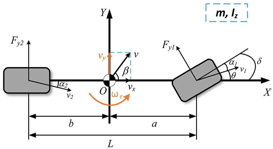
2-DOF vehicle model.
The simplified linear 2-DOF vehicle model can reflect the essential characteristics of the vehicle curve motion, and the yaw rate calculated by this model is used as the expected value to design the vehicle stability controller.
Equation (1) can be rearranged and expressed as follows in the form of state equation.

where
When the longitudinal speed of the vehicle remains constant and reaches a steady state, conditions

where

The upper limit of vehicle yaw rate can be determined as equation (5).

Therefore, the expected yaw rate based on the 2-DOF reference vehicle model is shown in equation (6).

Motor model
Permanent magnet synchronous motors (PMSMs) are selected as the driving motors. To increase the output torque, a single-stage planetary gear reducer with a reduction ratio of 12.5 is adopted. This paper simplifies the motor model by adopting the actual experimental data. Figure 2 illustrates the torque-speed characteristic curves of the motor at full load under driving and braking conditions.

Torque-speed characteristics of motors at full load.
The motor model can be expressed as shown in equation (7).

where
Vehicle controller design
In this paper, the linear 2-DOF vehicle model is taken as the reference model, and the driving torque required is obtained according to the speed-following controller. According to the vehicle stability requirements, the desired additional yaw-moment of the vehicle under the current driving state is calculated based on the AFLQR. Each wheel is then assigned a driving torque calculated by the torque distribution controller. The structure of the direct yaw-moment hierarchical control strategy is shown in Figure 3.

Structure diagram of direct yaw-moment hierarchical control strategy.
In vehicle stability control, many uncertainty factors, such as sensor noise and model errors, affect the control efficiency of the controller. To mitigate the negative impact of uncertainty, scholars have employed multi-sensor measurements and algorithmic estimation to obtain specific vehicle parameters (e.g., steering wheel angle, vehicle speed, lateral acceleration, sideslip angle, and yaw rate).37–39 These parameters are then used to infer the vehicle’s stability state accurately. This study rests upon the supposition that the vehicle’s longitudinal speed, sideslip angle, yaw rate and steering angle can be ascertained through measurement or estimation.
Speed-following controller
A vehicle speed-following control model is designed based on PI control. The mathematical model of the vehicle speed-following controller is shown in equation (8).

where
LQR controller
In this research, the linear 2-DOF vehicle model is used as the reference model, and the additional yaw moment

where
By subtracting equation (9) from equation (2), the state equation of the deviation value can be obtained as equation (10).

Letting state vector

It can be seen that the linear time-invariant system

In equation (10), the semi-positive definite matrix
AFLQR controller
The fixed
The performance of the LQR controller is related to the selection of weighting matrices
According to the above analysis, when selecting the weight coefficient
Selecting the difference between vehicle speed and 16.67 m/s (

Membership function of fuzzy control: (a) input variable
According to the above theoretical analysis of the vehicle dynamics, more emphasis should be placed on the
Fuzzy control rules.
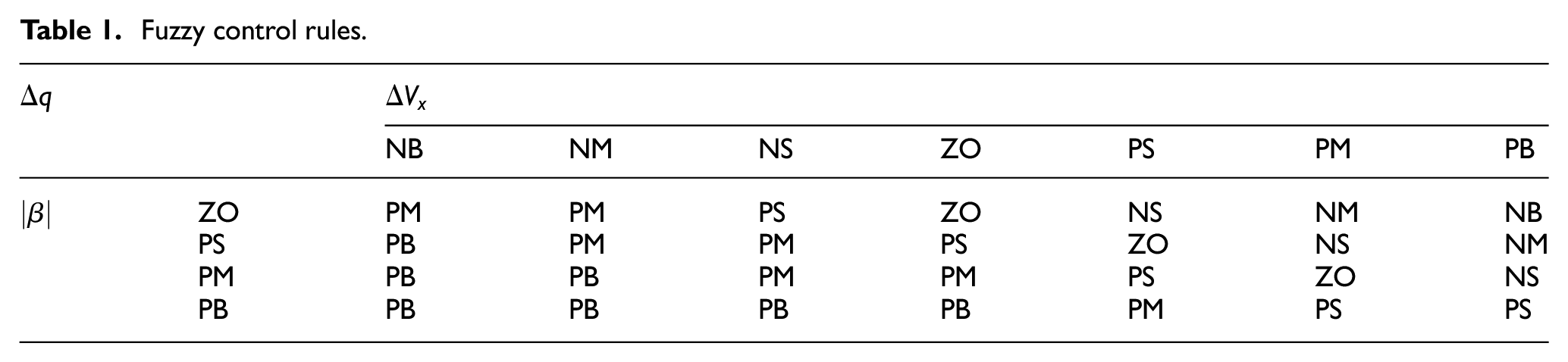
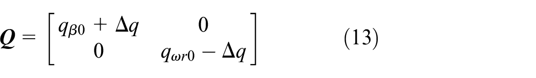
According to the fuzzy strategy, the matrix

where
For the system stability analysis, we use Lyapunov stability theory to prove it. First, define the Lyapunov function:

where
Then, find the first order derivative of

Substituting

Substituting

The solution

where
Torque distribution controller
The key technology for distributed electric drive vehicles is to reasonably distribute the driving torque of each wheel and ensure vehicle dynamics and stability.
During the driving process, each wheel’s load changes. To avoid the change in vehicle stability caused by the change in wheel load, this paper presents a tire-dynamic-load-based torque distribution strategy. Firstly, the left and right wheel torques are distributed according to the total driving force and the additional yaw moment to obtain the total driving torques of the left and right wheels, respectively, 41 as in equation (20). For each wheel, the driving torque of each driving wheel is as equation (21).

where

In the equation,

where
The vehicle controller unit first calculates the driving torque of each wheel. Then, the torque command is sent to the motor model, and a look-up table obtains the actual motor output torque. The output torque of each driving wheel is shown in equation (23).

where
In this paper, the proposed control strategy involves both upper and lower controllers. The upper controller mainly calculates the additional yaw moment through AFLQR control, and the lower controller distributes the torques through the tire-dynamic-load-based method, with the control objective of improving vehicle handling and stability. The proposed control offers several advantages: (1) AFLQR adjusts the weights of the sideslip angle and yaw rate based on vehicle speed and sideslip angle, ensuring handling and stability under varying conditions; (2) the integration of fuzzy logic enhances the controller’s robustness, adaptability, and alignment with engineering requirements by effectively operating in uncertain environments; (3) the use of a tire-dynamic-load-based method accounts for load variations on the wheels, improving practical vehicle performance. However, the proposed control has a disadvantage: LQR control is designed for linear systems, necessitating the linearization of the nonlinear vehicle model before the proposed AFLQR controller design. Improper vehicle model linearization can potentially degrade the performance of the proposed controller.
Results of simulation and experiment
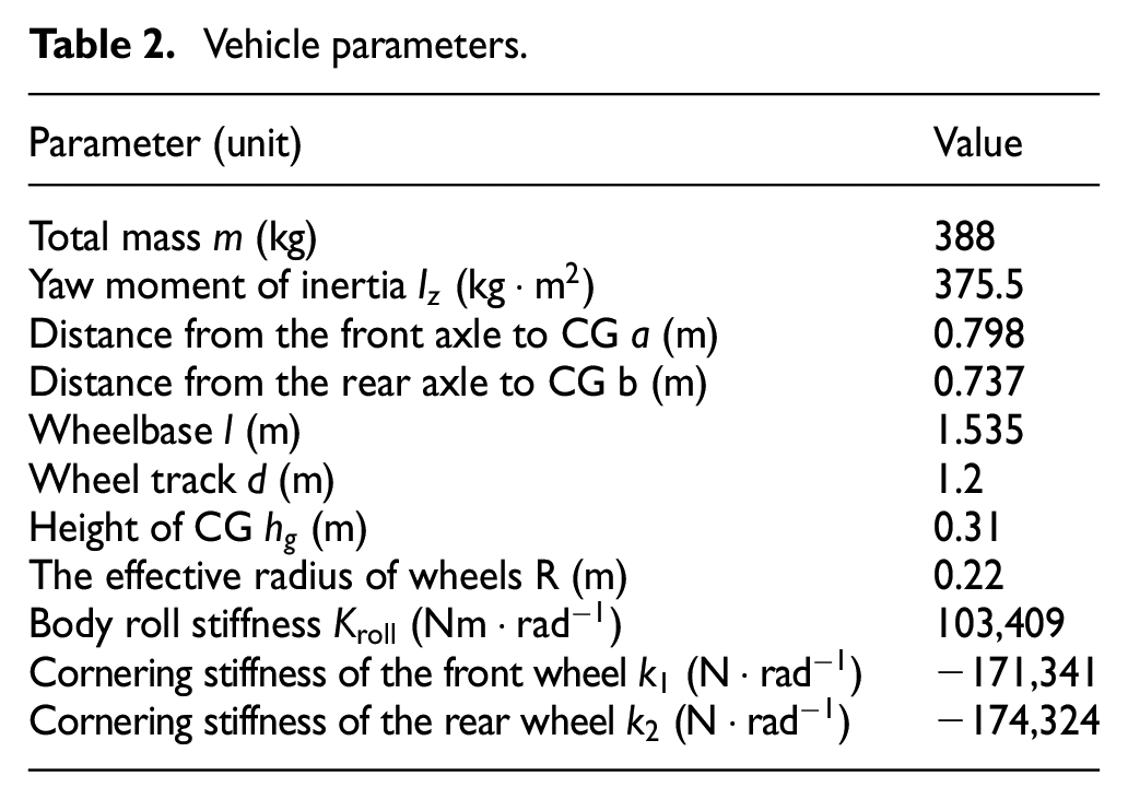
To assess the performance of the DYC based on AFLQR for the DDEV, CarSim was used to set the nonlinear multi-degree-of-freedom vehicle model, and Simulink was used to build the stability control strategy and motor models in this section. CarSim and Simulink built the co-simulation platform. The research object of this paper is a 4WID-EV partaking in the Formula Student Electric China (FSEC) championship. The vehicle parameters are shown in Table 2.
Vehicle parameters.
To better compare the effect of different control strategies, vehicles with four different control strategies are listed, namely, “Non-Yaw Control,”“LQR control,”“SMC,” and “AFLQR control.” The “Non-Yaw Control” stands for a non-yaw stability controlled DDEV, a four-wheel drive electric vehicle whose total drive torque is distributed equally to each wheel. The “LQR Control” stands for a DDEV fitted with a conventional LQR (fixed weight parameter) controller that utilizes a dynamic load torque distribution method. The “SMC” stands for a DDEV with a sliding mode control (SMC) that utilizes a dynamic load torque distribution method. The “AFLQR Control” stands for a DDEV fitted with an AFLQR controller that utilizes a dynamic load torque distribution method. To make the results more convincing, the initial weight parameters of the AFLQR are set the same as those of the LQR, and the torque distribution method adopted by DDEV fitted with AFLQR controllers is the same as that adopted by DDEV fitted with LQR controllers and SMC, which is based on the dynamic load torque distribution. Based on the four control strategies, the DDEVs are simulated under sinusoidal and double line change conditions, respectively, and the hardware-in-the-loop (HIL) experiment was carried out based on the NI-PXI platform.
Sinusoidal steering wheel input simulation
Simulation conditions: the vehicle speed is set to 80 km/h (49.71 mph), the road adhesion coefficient is 0.85, and the steering wheel input is a sinusoidal angle input with a period of 5 s and an amplitude of 90° after 1 s straight ahead. Figure 5 shows the steering wheel angle input, and the simulation results are shown in Figure 6.

Steering wheel angle input under sinusoidal condition.

Sinusoidal steering wheel input simulation results: (a) driving trajectory, (b) longitudinal velocity, (c) sideslip angle, (d) Yaw rate, and (e) driving torque of each wheel.
Figure 6(a) shows the vehicle driving trajectory curves under different control strategies. It can be seen that the lateral displacement deviation of vehicles with the non-yaw stability control is larger, and the lateral displacement deviation of vehicles with AFLQR control is slightly smaller than that with LQR control and SMC. Figure 6(b) shows the longitudinal velocity curve. It can be seen that the overshoot is larger when there is non-yaw stability control, and the speed-following effect is better when there is yaw motion control. Figures 6(c) and (d) show the sideslip angle and yaw rate response when different control strategies are adopted. The deviation of sideslip angle and yaw rate with non-yaw stability control is significantly higher than that with yaw motion control. Without yaw control,
Figure 6(e) shows the wheel drive torque curve. It can be seen that the right wheel torque is greater than the left wheel torque at the beginning of the left turn, and then the wheel torque changes with the change of the additional yaw moment. When the additional torque is larger, one wheel motor is in braking mode, and the other wheels are in driving mode.
To demonstrate the control effect of different control strategies more intuitively, two evaluation metrics are now introduced: maximum error of sideslip angle from the desired value
Comparison of different control strategies under 80 km/h sinusoidal steering wheel input simulation.

Double lane change simulation
The double lane change (DLC) simulation was carried out according to the standard condition of double lane shift in ISO3888-2:2002. The road adhesion coefficient was selected as 0.85, the simulation speed was set as 110 km/h (68.35 mph), and the simulation time was set as 8 s. The vehicle state response was obtained, as shown in Figure 7.

Double lane change simulation results: (a) driving trajectory, (b) longitudinal velocity, (c) sideslip angle, (d) yaw rate, and (e) driving torque of each wheel.
Figure 7(a) shows the trajectories of vehicles with different strategies. It can be seen that the vehicle cannot be stabilized without yaw control, but with yaw control, the vehicle can drive along the target trajectory. The lateral displacement deviation with AFLQR control was slightly smaller than that with LQR control and SMC. Figure 7(b) shows that the speed can follow the target value with yaw control. Figure 7(c) and (d) show the sideslip angle and yaw rate response under different control strategies. The vehicle will eventually lose stability without yaw control, so the deviation of the sideslip angle and yaw rate is significantly higher than that with yaw control. When there is no control,
In the model-in-the-loop (MIL) simulation, the sinusoidal steering wheel input condition and double lane change (DLC) condition are implemented, and the simulation results are shown: (1) In both conditions, the vehicle equipped with stability control maintains the absolute value of the sideslip angle below 5°. Additionally, the proposed AFLQR achieves a further reduction in the sideslip angle by over 7% and 5% compared to LQR and SMC, respectively; (2) compared with LQR control and SMC without adaptive control, the proposed AFLQR reduces the maximum error of yaw rate by 72.55% and 64.10% respectively at 80 km/h medium speed sinusoidal steering wheel input. Besides, at 110 km/h high-speed double lane change, the AFLQR significantly reduces the maximum error of yaw rate by 84.29% and 75.56%, respectively; (3) in addition to improving the vehicle’s stability and handling performance, the proposed AFLQR also increases trajectory following performance. In the double lane change condition, the AFLQR reduces the maximum error of lateral distance from 0.26 m with LQR and 0.25 m with SMC to 0.23 m. Through the quantitative analysis of simulation outcomes across various control strategies, it is believed that the proposed AFLQR control enhances the handling and stability of FSEC electric vehicles compared to LQR control and SMC. This enhancement contributes to bolstering driver confidence and promoting driving safety (Table 4).
Comparison of different control strategies under 110 km/h double lane change simulation.

Hardware-in-the-loop experiment
The simulation part of the above belongs to the model-in-the-loop (MIL). To further verify the control strategy’s effectiveness and the controller’s real-time application, a real controller from DDEV was introduced, and a HIL experiment platform for the AFLQR controller was built in this experimental section. As shown in Figure 8, the HIL test platform includes a CarSim vehicle model, simulator and vehicle controller. CarSim software established the vehicle simulation model. The simulator adopts the NI-PXie-1085 system, including a program-controlled power supply, PXIE-6363 multi-function I/O board, NI-PXIE-8880 real-time processor, and PXie-8510 vehicle multi-protocol interface module. The test platform software is the NI Veristand system. The vehicle controller is an ECU developed by NXP’s MPC56xx. The specific working process is as follows: First, the vehicle control program is designed based on the vehicle model, and the ECUCoder is used to generate control software code with one click of the program and write it into the vehicle controller. By setting the connection between the controller and the real-time model through NI Veristand, the simulator and the vehicle controller are communicated in real-time through the CAN bus. The controller obtains vehicle state parameters from the simulator, calculates each wheel’s driving torque command through the vehicle controller, and sends it to the vehicle model in the simulator. Finally, the real-time simulation system is performed, and the vehicle model is controlled to operate according to the torque command transmitted by the controller under the given driving conditions. The calculation time within each control step is 0.0005s.

Structure of the hardware-in-the-loop platform.
The HIL test experimental condition selects a double lane change test. The desired vehicle speed, road surface and other experimental conditions were the same as those in section “Double lane change simulation.” The test results are shown in Figure 9 and Table 5.

Hardware-in-the-loop experiment results (based on AFLQR control under double lane change condition): (a) driving trajectory, (b) longitudinal velocity, (c) Sideslip angle, (d) yaw rate, (e) driving torque of front wheels, and (f) driving torque of rear wheels.
Comparison of MIL simulation’s and HIL experiment’s stability variable curve peak values.

where
As shown in Figure 9(a), it can be seen that the vehicle can follow the target path under the HIL experiment. The curve deviates at the inflexion point of the trajectory but does not exceed the position of the test stake, so it meets the experimental requirements. It can be seen from Figure 9(b) that the vehicle speed can follow the target speed, and there is a certain fluctuation compared with the MIL simulation results. Figure 9(c) and (d) show the high fit of the HIL experiment to the MIL simulation, respectively (the deviation of sideslip angle and yaw rate are 0.15% and 0.14%, respectively), which further validates the excellent control effect and feasibility of the AFLQR controller in real controllers. In the HIL experiment, the maximum deviation of the sideslip angle from the desired value is 2.57°, and the maximum deviation of the yaw rate from the desired value is 0.20°/s, achieving commendable stability and meeting this vehicle’s stability design requirements.
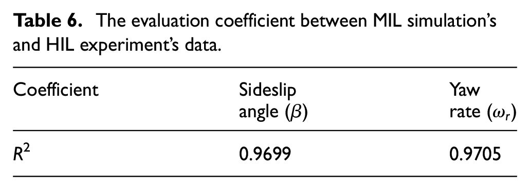
The evaluation coefficient between MIL simulation’s and HIL experiment’s data are shown in Table 6. From Table 6, it can be seen that the R2 value of the sideslip angle of the vehicle is 0.9699, and the R2 value of the yaw rate is 0.9705, which indicates that the proposed control strategy can still operate well in the hardware device with good reliability.
The evaluation coefficient between MIL simulation’s and HIL experiment’s data.
Conclusions
The main research works and findings are listed below:
(1) Permanent magnet synchronous motors (PMSMs) were selected as the driving motors, and a distributed drive electric vehicle (DDEV) model was developed to supply a reliable basis for direct yaw control (DYC).
(2) Based on the highly recognized linear 2-DOF yaw plane vehicle model, LQR control and fuzzy logic, an adaptive fuzzy linear quadratic regulator (AFLQR) controller was proposed to control the vehicle’s handling and stability in different working conditions. The control strategy concentrated on adjusting the weights of the desired sideslip angle and the desired yaw rate following under various conditions.
(3) With the application of the same dynamic load torque distribution method under the sinusoidal steering wheel input condition and double lane change condition, the proposed AFLQR reduced the sideslip angle by 7.14%, which gave the vehicle excellent handling performance. The proposed AFLQR adjusted the weights of the vehicle’s handling and stability. Compared with LQR without adaptive control, the AFLQR reduced the maximum error of yaw rate by 72.55% under the 80 km/h sinusoidal steering wheel input condition. Besides, the AFLQR significantly reduced the maximum error of yaw rate by 84.29% at 110 km/h under high-speed double lane change condition. In addition to improving the vehicle’s stability and handling performance, the AFLQR also increased the trajectory following performance. Under double lane change conditions, the AFLQR reduced the maximum error of lateral distance from 0.26 m with LQR and 0.25 m with SMC to 0.23 m.
(4) The hardware-in-the-loop (HIL) experiment further verified the effectiveness of the hierarchical control strategy containing the AFLQR controller + dynamic load torque distribution method. The peak deviations of sideslip angle and yaw rate between the HIL experiment and the MIL simulation were less than 0.2%, which further proved the effectiveness of the proposed control strategy. During the HIL experiment, the maximum deviation of the sideslip angle from the desired value was 2.57°, while the maximum deviation of the yaw rate from the desired value was 0.20°/s. These deviations attained commendable stability, satisfying the stability design requirements for this vehicle.
This paper conducts specific research concerning the adaptive control over the distributed drive electric vehicle’s stability and handling in different conventional stability states. During the design and simulation of the control strategy, we have traditionally operated under the assumption that the ground imparts an ample reactive force onto the tires. We have thus far disregarded the potential impact of wheel lockup or slip on the efficacy of control. In the future, making the control strategy more compatible with realistic driving conditions by thoroughly investigating the effect of wheel lockup and slip on the adaptive control can be taken as a further research topic.
Footnotes
Handling Editor: Aarthy Esakkiappan
Declaration of conflicting interests
The author(s) declared no potential conflicts of interest with respect to the research, authorship, and/or publication of this article.
Funding
The author(s) disclosed receipt of the following financial support for the research, authorship, and/or publication of this article: This work was supported by the Natural Science Foundation of China (Grant No. 52072116), the Key Research and Development Projects of Hubei Province (Grant No. 2020BAB141) and the Special Fund of Hubei Longzhong Laboratory of Xiangyang Science and Technology Plan.