
Abstract
We develop a program for predicting bearing performance, including the maximum contact stress, bearing power loss, minimum lubricating film thickness, static safety factor, and dynamic life, and an optimal design for high-speed angular contact ball bearings in aircraft gearboxes using optimization algorithms. A program is developed to predict bearing performance by calculating the loads and displacements of individual balls based on the bearing’s kinematic and static equilibrium equations. Next, an optimization program is developed with non-dominated sorting genetic algorithm III (NSGA-III), wherein calculated bearing performance indicators serve as constraints or objective functions. The performance of individuals within the final Pareto front is evaluated using the inter-criteria correlation (CRITIC) and weighted product methods. The optimization performances of NSGA-III and NSGA-II are compared based on their hypervolume indicators. A solution of the kinematic and static equilibrium equations under the load cases and duty cycles of real aircraft gearboxes is obtained, enhancing the prediction accuracy. Furthermore, optimization, including bearing performance metrics rarely considered in previous studies, is performed. Optimal specifications superior to reference bearings employed in aircraft gearboxes are obtained, enhancing all three objective functions or specific objective functions. The optimization performance of NSGA-III is confirmed to surpass that of conventional NSGA-II.
Keywords
Introduction
Bearings are essential mechanical components installed on the shafts of gearboxes to secure the rotating input shaft at a designated position, support the axial loads generated by gear meshing, and facilitate smooth shaft rotation. Rolling element bearings comprise two rings with a set of rolling elements running on their tracks. Because of their low starting torque and kinetic friction, rolling element bearings are widely utilized in various industrial machines, such as automobiles, aircraft, ships, construction equipment, and robots.1,2
Bearings installed in aircraft gearboxes must withstand harsh operating conditions characterized by high-speed operation, high loads, and severe environmental conditions such as high temperatures and altitudes, distinct from those in automotive and general industrial applications. 3 Bearings designed for electric vehicle gearboxes are being studied to accommodate the high speed of electric motors.4–6 However, the loads acting on these bearings are significantly lower than those acting on bearings in aircraft gearboxes. Aircraft gearbox bearings are required to support high axial and radial loads at high rotational speeds. They are exposed to various external conditions owing to the elevated temperatures and altitudes associated with gas turbine engines. Consequently, aircraft gearbox bearings require an optimal design and precision manufacturing to ensure smooth operation under more severe loads and environmental conditions than conventional bearings. Bearings must satisfy the stringent reliability requirements of aircraft gearboxes, including their performance, lifespan, and environmental durability. 7
Bearings designed for aircraft gearboxes, characterized by their unique requirements, often cannot be selected from standard bearing catalogs provided by manufacturers. Engineers must undertake custom designs of nonstandard bespoke bearings that satisfy aircraft gearboxes’ performance, lifespan, and environmental durability requirements. The bearing performance is influenced by the internal geometry of the bearing, making it crucial to select optimized bearing specifications to satisfy the required performance. Engineers have developed computer-aided engineering tools for performing analysis-based designs and evaluating nonstandard custom bearings’ performance. 8 However, these bearing design methods typically involve trial and error processes that require significant time, effort, and computational power from the PC.
To address these challenges, optimization techniques have been proposed for the optimal design of nonstandard custom bearings. Studies have also been conducted in this regard. Chakraborty et al. utilized genetic algorithms to maximize the dynamic load rating of deep-groove ball bearings. 9 Rao and Tiwari extended Chakraborty’s work by considering optimal design parameters such as the bearing width and constraints related to the raceway thickness. 10 Lin adopted a genetic algorithm, a differential evolution hybrid algorithm, to maximize the dynamic load rating of deep-groove ball bearings. 11 Duggirala et al. developed optimal designs utilizing crowding-distance particle swarm optimization to maximize the static load rating, dynamic load rating, and lubricating film thickness of deep-groove ball bearings. 12 Gupta et al. selected specifications that maximized the static load rating, dynamic load rating, and lubricating film thickness utilizing the non-dominated sorting genetic algorithm (NSGA) II (NSGA-II). 13 Tiwari et al. utilized genetic algorithms to optimize the design of a tapered roller bearing to maximize its static load rating. 14
These studies focused on optimizing the designs of deep-groove ball bearings and tapered roller bearings. However, bearings utilized in aircraft gearboxes must withstand very high axial loads compared to those utilized in other applications. Consequently, angular contact ball bearings, better suited than deep-groove ball bearings for sustaining high loads, are primarily applied. 15 Numerous studies have been conducted on the angular-contact ball bearings. Wei and Chengzu utilized the NSGA-II to maximize the dynamic life and minimize the frictional power loss of high-speed angular contact ball bearings. 16 Kim et al. targeted angular contact ball bearings on a grinder main shaft. They developed optimal designs to maximize the radial and axial stiffness utilizing micro-genetic algorithms and the progressive quadratic response surface method. 17
However, these studies on angular contact ball bearings for high-speed conditions often have limitations in that they consider only a few performance metrics of the bearings as objective functions.9–14,18 Beyond the dynamic life, frictional power loss, and stiffness, other critical bearing performance indicators such as the safety factor, minimum lubricating film thickness, bearing power loss, and maximum contact stress are also critical, particularly for aircraft gearbox bearings operating under severe conditions such as high speeds, loads, and temperatures. Therefore, a comprehensive approach that considers various objective functions for minimization and maximization is required to optimally design the angular contact ball bearings utilized in aircraft gearboxes. Here, the following bearing performance metrics were considered as the optimization objective functions and constraints: (a) safety factor, (b) dynamic life, (c) maximum contact stress, (d) bearing power loss, and (e) minimum lubricating film thickness.
Previous studies considered optimizing the static safety factor and dynamic life of bearings during the optimization process; however, static and dynamic load ratings were utilized as the objective functions to maximize them. It is necessary to design bearings that satisfy the minimum static safety factor in the actual gearbox design process based on the type of operation instead of maximizing the static load rating. In addition, although maximizing the dynamic rating may not be critical, designing bearings that satisfy the minimum dynamic life requirement determined by the loading cases and duty cycles is essential. Therefore, it is crucial to determine the loading cases and duty cycles acting on the actual gearbox and calculate the loads and displacements of each ball based on the kinematics of the bearing and the static equilibrium equations of the ball and raceway. Here, the details of the loading case and duty cycle acting on an actual aircraft gearbox are determined, and the kinematic and static equilibrium equations of the bearing are solved via numerical analysis techniques to compute the static safety factor and dynamic life. Furthermore, the calculated static safety factor and dynamic life were not set as objective functions but as constraints. Other bearing performance metrics (maximum contact stress, bearing power loss, and minimum lubricating film thickness) with no specific requirement conditions were set as the objective functions for the optimal design.
Various optimization techniques have been proposed to solve engineering problems. Bearing design processes utilizing various optimization methods have also been the subject of extensive research via various optimization methods. Some researchers have adopted genetic algorithms to maximize the dynamic load rating of bearings, but they have primarily focused on single-objective optimization.9–11,14 Bearing design involves multiple performance metrics, making employing algorithms suitable for multi-objective optimization problems necessary. Hence, some researchers utilized NSGA-II to optimize bearings by considering various performance metrics as the objective functions.12,13
However, Yannibelli et al. reported that NSGA-III outperformed NSGA-II when evaluating various performance metrics with the L2-norm, which jointly assessed the makespan, cost, and number of task failures caused by out-of-bound errors. 19 Ciro et al. also found that NSGA-III performed better than NSGA-II when dealing with problems with multiple objective functions, owing to the process of defining a hyperplane and reference points to classify solutions and select the best candidates for the next population. 20 Furthermore, Teymourifar et al. observed that NSGA-III outperformed NSGA-II in terms of obtaining more nondominated solutions. 21
Here, we employed NSGA-III, which has not been previously utilized for optimal bearing design. Furthermore, we compared the performances of NSGA-II and NSGA-III in the context of the optimal bearing design by calculating the hypervolumes and analyzing the results of both algorithms.
In summary, the main contributions and innovativeness of this study are as follows.
The optimal design approach utilized here represents a significant advancement in the field because it comprehensively incorporates various performance metrics that have not been extensively addressed in previous studies. By considering performance metrics such as the static safety factor, dynamic life, bearing power loss, maximum contact stress, and minimum lubricating film thickness, this study provides a more thorough understanding of the behavior of bearings under diverse operating conditions.
This study considered the actual load cases and duty cycles of aircraft gearboxes, which previous studies have not considered. In addition, the bearing’s kinematic and static equilibrium equations were solved. Via this process, the actual safety factor and dynamic life of the bearings were calculated. This realistic approach enhances the applicability and reliability of optimized designs for practical aircraft applications.
The application of NSGA-III for bearing specification design showcases a methodological innovation, leveraging the algorithm’s superior performance compared to NSGA-II, as supported by the existing literature. This choice demonstrates our commitment to employing cutting-edge optimization techniques to achieve optimal designs in high-performance engineering systems.
Overall, this study contributes a holistic and practical framework for designing high-speed angular contact ball bearings, making notable strides in addressing key performance indicators and employing advanced optimization methodologies for enhanced efficiency and reliability in aircraft applications.
Static equilibrium of angular contact ball bearing
Coordinates of angular contact ball bearing
Gearbox bearings were installed on the shafts to support the loads and moments generated by gear meshing. The loads and moments on the bearings can be broadly categorized into radial, axial, and tilting moments. The magnitudes of the loads and moments on the bearings can be calculated based on factors such as the gear meshing force applied by the gear pair, length of the shaft, and location where the bearing is installed. As loads and moments act on the bearing, each rolling element that constitutes the bearing experiences stress and displacement.
Here, it is necessary to first calculate the loads and displacements of each rolling element under the given bearing load conditions to determine the maximum contact stress and dynamic life as performance indicators of the bearing. For the angular contact ball bearing analyzed here, the load on each ball was influenced by internal geometry factors such as the number of balls, ball diameter, pitch diameter, inner and outer raceway curvature radii, and initial contact angle. Mathematical calculations were performed with kinematic and static equilibrium equations of the bearings. Sections “Coordinates of angular contact ball bearing” to “Determination of contact load and stress” describe the calculation process outlined in the references in a clear and concise manner.1,2
Figure 1 illustrates the Cartesian coordinate system of the bearings utilized here. The axis on which the bearing was mounted was defined as the x-axis, whereas the y- and z-axes were the two radial axes orthogonal to the x-axis. The r-axis is an arbitrary reference axis passing through the center of each ball, and it is defined for the number of balls with intervals corresponding to the orbital angles,


Bearing coordinate system.
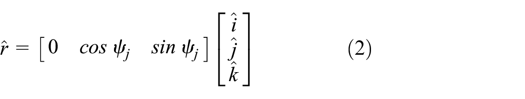
Unit vectors
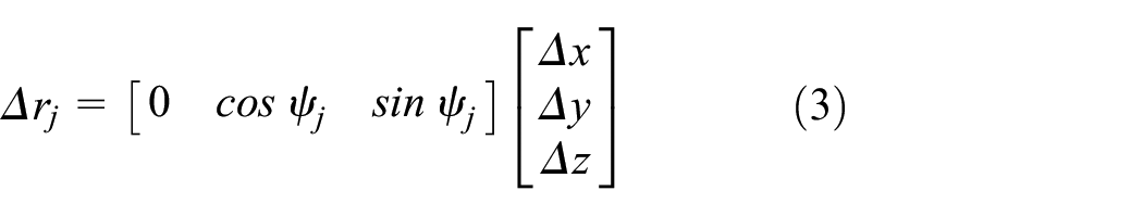
Subsequently, five relative displacements (

Relative race displacements, miscellaneous frames, and sign convection.
The equations in the contact plane defined by the orbital angle

Determination of displacement and contact angle for each ball


Inner and outer raceway curvature centers and contact angle.
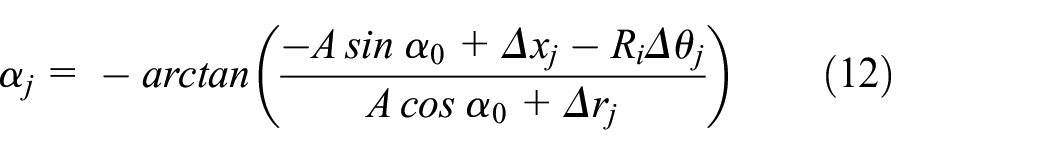
By defining the auxiliary parameter

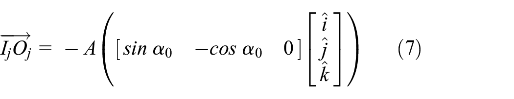

When displacements occur in the bearing, the coordinates of
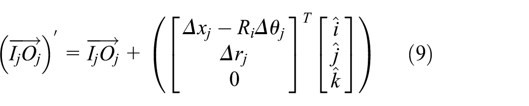
where

The deformation

Determination of contact load and stress
The displacements and changes in the contact angles of each ball induced by the loads and moments on the bearing can be calculated by following the processes outlined in equations (1)–(12). Determining the point contact stiffness between each ball and the inner and outer races enables calculation of the loads on each ball. Furthermore, the contact stress can be calculated with the knowledge of the point contact area. To determine the point contact stiffness and the contact stress, assumptions were made regarding both elastic deflection of point contact and Hertizan contact. The Hertz theory of the contact between two elastic solids is widely employed to calculate the point contact stiffness and point contact area.22–24 Hertz theory is based on the calculation of elliptical functions, which can be conveniently performed with tables or charts.25,26 The calculation process is described in Hertz’s paper and in numerous textbooks and handbooks27–29; therefore, this paper does not present a detailed calculation procedure. The load on each ball,


The loads and contact stresses for each ball calculated with equations (13) and (14) were adopted as constraints and objective functions in the subsequent optimization process, particularly to determine the dynamic life and maximum contact stress. Further details are provided in Sections “Maximum contact stress” and “Basic reference rating life.”
Formulation of angular contact ball bearing problem
Design parameters
Figure 4 presents the key specifications of the bearings utilized here. The bearing design variables for optimal bearing design are as follows: (a) number of balls,

Macrogeometries of angular contact ball bearing.
The main specifications for the bearing, including the inner diameter
The inner raceway groove curvature coefficient


Objective functions
Maximum contact stress
Fatigue cracks are initiated at specific weak points, such as slag and nonmetallic inclusions, located beneath the surface of a bearing ring, typically at a depth where the shear stress is maximized at 45° in the direction of rolling. When the roller traverses the surface, the subsurface experiences alternating shear stress, ultimately resulting in fatigue cracks. 30 The contact stress that occurs when the balls of the bearing come into contact with the inner and outer races generates orthogonal and maximum shear stresses below the surface. These shear stresses are the primary cause of subsurface fatigue, making it essential to minimize contact stress to prevent subsurface fatigue in the bearing race. 31 Therefore, the maximum contact stress between the balls and the race was set as the objective function to minimize the contact stress.
As expressed by equation (14), contact stresses

Bearing power loss
When a rolling bearing rotates, a significant amount of power is dissipated, which increases significantly, particularly at high speeds. 32 The bearing power loss refers to the power dissipated by the bearing during operation. This is one of the main causes of reduced gearbox efficiency alongside gear loss. 33 Therefore, here, the bearing-power loss was set as the objective function to minimize the decreased efficiency of aircraft gearboxes operating at high speeds.
The bearing power loss


Minimum lubricating film thickness
Adequate lubrication reduces friction and wear between the ball and bearing races. Inadequate lubrication can induce metal-to-metal contact, reducing the wear life of the bearing and causing premature failure, eventually impairing the smooth operation of the gearbox and the aircraft’s mission performance. The lubricating film thickness can be determined by the elastohydrodynamic lubrication theory to ensure effective bearing lubrication. 35 Therefore, the minimum lubricating film thickness between the balls and raceways was set as the objective function to be maximized to minimize friction and wear. The calculation process is expressed in equations (22) and (23).

The subexpressions utilized to compute the film thickness are as follows.


Constraints
Static safety factor
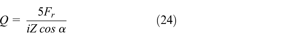
The static safety factor

The recommended value of the static safety factor for a ball bearing depends on the type of operation. When accurate information on the magnitude of shock loads is unavailable, the static safety factor should be at least 1.5 or higher.
36
Therefore, the first constraint related to the static safety factor, denoted by

Basic rating life
The basic rating life,


Basic reference rating life
The basic reference rating life
Similar to the basic rating life, the basic reference rating life was set to a minimum of 13,000 h. The third constraint, which is related to the basic reference rating life, is denoted by


Geometric constraints
For the ease of bearing production, the constraints
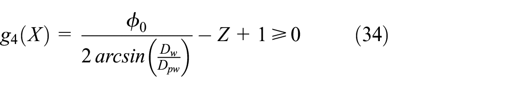

In addition, the ball diameter has upper and lower bounds, as expressed in equation (37).

Therefore, Constraints


Furthermore, a slight difference exists between the pitch diameter and average bearing diameter (the average of the inner and outer diameters) for the running mobility of the bearing; the constraints are given by equations (40) and (41). 39


Finally, the inner and outer raceway groove curvature coefficients have the constraints expressed by equations (42) and (43). 10


Optimization results and discussion
Methodology implementation
The optimal design of the angular contact ball bearing here involved multiple objective functions, which necessitated the utilization of a multi-objective optimization (MOO) algorithm.12,13,16,17 Several algorithms have been utilized for multi-objective optimization in bearing design. However, NSGA-III has not yet been utilized in bearing-design processes. NSGA-III outperforms NSGA-II, particularly when dealing with three or more objective functions.19–21,40,41 Therefore, NSGA-III was utilized here as the MOO algorithm to optimize the design of the angular contact ball bearing.
A real-coded NSGA-III algorithm was employed for the optimization process (Figure 5). We employed a binary tournament selection method to select parents for reproduction and performed crossover and mutation with 5% probability. 42 The population size was set to 500, and the iterations were carried out over 200 generations. A multicriteria decision-making method known as the CRITIC method was adopted for decision-making. The CRITIC method is preferred because of its ability to reflect the contrast intensity and conflicting relationships within each decision criterion, offering several advantages over entropy-based methods and TOPSIS.43–47

Flowchart of bearing optimization with NSGA-III.
Reference bearing
A reference bearing was selected to compare its performance with the optimal specifications obtained from the optimization results of a conventional bearing. The reference bearing is a high-speed angular contact ball bearing utilized in aircraft gearboxes. Its detailed specifications are presented in Table 1, and the lubrication information of the bearing is presented in Table 2.
Geometries of reference bearing.

Lubrication parameters in this study.

Some previous studies focused on maximizing the static and dynamic load ratings, neglecting the actual duty cycle. However, because this study utilizes the static safety factor and dynamic life as constraints based on the operating conditions of aircraft gearbox bearings instead of static and dynamic load ratings, the duty cycle details of the aircraft gearbox bearings are required. Table 3 presents the duty cycle information for the aircraft gearbox bearings; experienced aircraft designers provided these data.
Duty cycle of aircraft gearbox bearing.

Optimization details
The optimization process involved the evolution of 500 individuals per generation over 200 generations. The lower, upper, and step sizes of the design variables are listed in Table 4. The inner and outer diameters, listed in Table 1 for the reference bearing, were determined based on the diameter of the shaft and the available installation space for the bearing. These parameters could not be arbitrarily changed during the bearing design process; therefore, they were excluded as design variables. The design variable ranges were selected to remain within reasonable limits of the reference bearing specifications and satisfy the geometric constraints outlined in Section “Geometric constraints,” ensuring the resulting design is feasible.
Ranges and step sizes of design variables.

Results and discussion
Optimization results
The optimal design results are compared with those of the reference bearing, as outlined in Section “Reference bearing.”Table 5 presents the results of the Pareto-front individuals for both the reference bearing and optimal design, including the design variables, output values, and objective functions. The weights for each objective function were calculated with the CRITIC method, and the weighted product was computed accordingly. Based on the weighted product value, the top ten individuals and three individuals who minimized each objective function were selected for presentation.
Optimization results.

Individuals with the highest weighted product (Rank 1) exhibited improvements in all three objective functions compared with the reference bearing. Specifically, the maximum contact stress decreased by 11.40%, the bearing power loss decreased by 1.82%, and the minimum lubricating film thickness increased by 2.67%.
Furthermore, all individuals ranked up to 10 exhibited improvements in all three objective functions (Table 6). For example, 27 ranked individuals achieved a decrease of up to 16.79% in the maximum contact stress. Similarly, Rank 41 individuals underwent a decrease of up to 45.41% in the bearing power loss, and Rank 33 individuals increased the minimum lubricating-film thickness by up to 23.56%.
Hypervolume indicator values obtained with NSGA-III and NSGA-II.

Consequently, the multi-objective optimization process enabled the identification of optimal specifications that improved all three objective functions for high-speed angular contact ball bearings utilized in aircraft gearboxes. Moreover, the process identified specifications that could significantly improve one or two specific objective functions compared to the others. This provides a more convenient method for designers to select bearing specifications that satisfy design requirements during the design process.
Comparison analysis between NSGA-III and NSGA-II
As established, the NSGA-III can outperform the NSGA-II, particularly when dealing with problems involving more than three objective functions.19–21 Furthermore, NSGA-III exhibits better diversity ranking compared to other typical multi-objective optimization algorithms. 48 According to the study by Kim et al., when applied to gear optimization, NSGA-III successfully captured a diverse set of solutions, outperforming other MOO algorithms such as KnEA, MOMBI-II, and RPEA, affectively handling a discontinuous design distribution. 49 That is, it was revealed that NSGA-III yields superior results in the optimal design process of machine elements with discontinuous design distributions, such as gears and bearings, compared to other MOO algorithms. Therefore, NSGA-III was utilized for the multi-objective optimization of the bearings here, in contrast to previous studies that utilized NSGA-II. However, previous research has not quantitatively compared NSGA-II and NSGA-III in the optimal design process of machine elements. An optimization process was performed with only NSGA-II to confirm whether NSGA-III performed better than NSGA-II. The population size was also set to 500, iterations were carried out over 200 generations, and the crossover and mutation rates were set to 5%, the same as for NSGA-III. The performances of the NSGA-II and NSGA-III in the bearing optimization process were evaluated by determining the hypervolume indicator.
The hypervolume indicator is effective for evaluating results in evolutionary multi-objective optimization problems because it is Pareto compliant, can simultaneously assess the convergence and diversity of solution sets, and requires the specification of only one reference point.50–52 A higher hypervolume indicator value indicates that the optimization results cover a wider area in the multi-objective space, including solutions that balance multiple objectives and encompass a larger portion of the objective function space, representing a higher quality of optimization results. Auger et al. described hypervolume indicator values’ theory and calculation process. 53
Table 6 lists the hypervolume indicator values calculated based on the results of the optimization processes for NSGA-II and NSGA-III. The generation size and number of generations were varied to compare various cases, resulting in 12 cases for computing the hypervolume indicator of the final Pareto front. The results confirmed that in 10 of the 12 cases, the hypervolume indicator value of NSGA-III exceeded that of NSGA-II. In the two cases with the smallest generation size and number of generations, NSGA-II had a slight advantage in the hypervolume indicator values. However, as the size and number of generations increased, NSGA-III consistently outperformed NSGA-II in terms of the hypervolume indicator values.
Moreover, in most cases, the difference in the hypervolume indicator values between the NSGA-II and NSGA-III increased with increasing generations. NSGA-III generally demonstrated an increasing trend in the hypervolume indicator values with increasing generation sizes, whereas NSGA-II did not exhibit a clear increasing trend. Consequently, within the available computing power range, NSGA-III outperforms NSGA-II when sufficiently large generation sizes and numbers of generations are utilized.
In conclusion, this study demonstrated that NSGA-III, introduced for the first time in the optimization of high-speed angular contact ball bearings for aircraft gearboxes, outperforms NSGA-II. In future studies, when performing optimization with NSGA-III for various types of bearings, superior results are expected compared with previous findings.
Conclusion
This study attempted to develop a program for predicting the performance of bearings, including the maximum contact stress, bearing power loss, minimum lubricating film thickness, static safety factor, and dynamic life. In addition, the objective was to achieve an optimal design for high-speed angular contact ball bearings in aircraft gearboxes by applying optimization algorithms.
Initially, a program was developed to predict the performance of the high-speed angular contact ball bearings utilized in aircraft gearboxes. The programming involved defining the static equilibrium equation of the bearing in the coordinates defined by the bearing and bearing balls. The program predicted various bearing performance indicators by incorporating the actual duty cycle details of the aircraft gearboxes. This approach considered parameters such as the static safety factor, dynamic life, maximum contact stress, bearing power loss, and minimum lubricating film thickness, which have often been neglected in previous studies.
The obtained static safety factor and dynamic life served as constraints. In contrast, the maximum contact stress, bearing power loss, and minimum lubricating film thickness were set as the objective functions in the developed optimal design algorithm. In contrast to conventional genetic algorithms focusing on single-objective optimization or the widely employed NSGA-II for multi-objective optimization, NSGA-III was employed in this study.
The evaluation results indicated that the optimized designs improved all three objective functions compared to the reference bearings utilized in conventional aircraft gearboxes. Indeed, among the entities classified under Rank 1, one exhibited a noteworthy decrease of 11.40% in the maximum contact stress, 1.82% in the bearing power loss, and an increase of 2.67% in the minimum lubricating film thickness. Furthermore, specific designs were identified for situations where a specific objective function must be maximized or minimized according to the designer’s requirements. When seeking to minimize the maximum contact stress, specifications resulting in a reduction of the maximum contact stress by up to 16.79% can be derived. Similarly, employing the same method, specifications leading to a decrease in bearing power loss by up to 45.41%, and an increase in the minimum lubricating film thickness by up to 23.56% can be obtained. In addition, the performance of NSGA-III was compared with that of the commonly utilized NSGA-II by determining the hypervolume indicator. The results consistently favored NSGA-III over NSGA-II, particularly when larger generation sizes and numbers of generations were adopted.
In conclusion, the developed program for predicting bearing performance and the NSGA-III-based optimal design algorithm is expected to facilitate the process of selecting bearings with optimal specifications. The direction for future study is as follows: Only the macro-geometry of angular contact ball bearings mounted on aircraft gearboxes was used as a design variable in this study. In subsequent research, including the micro-geometry in the optimization design process is expected to yield better optimal design specifications.
Footnotes
Appendix
Handling Editor: Yawen Wang
Declaration of conflicting interests
The author(s) disclosed receipt of the following financial support for the research, authorship, and/or publication of this article: This work was supported by the Korea Research Institute for Defense Technology Planning and Advancement (KRIT) grant funded by the Korean government DAPA (Defense Acquisition Program Administration) (No. KRIT-CT-21-013, Next Generation Rotorcraft Transmission Core Parts, 2021).
Funding
The author(s) received no financial support for the research, authorship, and/or publication of this article.