
Abstract
In the work, the differential equations of motion of the gyroscopic rotor, built taking into account the anisotropy of stiffness and damping of the flexible support, are solved analytically, by the method of harmonic balance, convenient for obtaining separately amplitude-frequency and phase-frequency characteristics in the direction of oscillations. The equations of the non-stationary process are obtained by the method of changing amplitudes. It has been found that when the linear stiffness of the elastic support is different in two orthogonal directions, two critical velocities and the corresponding resonant regions arise. In the area of each critical speed, there are two amplitude-frequency curves of oscillations of the main direction and the direction perpendicular to it, respectively. The geometric nonlinearity of damping suppresses the elevations of these amplitude-frequency curves more significantly than linear damping. If only one of the two directions has a damping nonlinearity, then its effect is on the amplitude-frequency curves of the corresponding critical speed. It is more efficient to control resonant amplitudes for smooth resonant transitions by enhancing the linear damping with geometrically nonlinear damping. The results of the analytical solution of the equations of motion agree well with the results of direct modeling and experimental studies.
Keywords
Introduction
As is commonly known, rotary machines are widely used in many industries and have been studied for a long time, and a sufficient amount of literature is devoted to the study of their dynamics. Despite this, there are many problems associated with vibrations that occur during the acceleration and deceleration of the machine, and the stationary mode of its operation. Their sources are, in particular, uneven mass distribution, malfunctions in the support structure and its bearings.
As a rule, a simplified model with lumped parameters is used to study the dynamics of the shaft of one rotor on the bearing supports. The supports, being between the shaft and the support structure, are the means of their connection; they have different shapes and structures, depending on specific assumptions. It is very important to use the properties and characteristics of the support material to dampen the vibration in order to stabilize the movement. In addition to choosing the optimal stiffness and optimal damping of the elastic support, a reasonable purpose of the accuracy of manufacturing of the support elements is necessary for the stable operation of the machine. The more precise dynamic design of the machine will allow the correct analysis of the elastic support operation.
The total deflection of the rotor consists of the deflection on the elastic support and the deflection of the shaft itself. In this case, only the deflections of the elastic support will be damped. Therefore, for maximum damping of oscillations, it is desirable to place the elastic support in the place of the greatest deflection, that is, as close as possible to the rotor.
It is known that linear damping of oscillations occurs in resonance zones and after them linear damping does not affect the amplitude value. It is proved that the geometric nonlinearity of damping in contrast to the linear damping, not only significantly suppresses the maximum resonant amplitude of oscillations, but also protects isolation from vibration in zones beyond the resonant frequency of oscillations and eliminates jumping effects.1–10 It is also proved that if the linear damping shifts the left boundary of the instability zone toward large amplitudes of oscillations and shaft rotation speeds, the geometric nonlinearity of the support damping narrows the instability zone from all its boundaries.5–8 The article by Al-Solihat and Behdinan 4 has experimentally confirmed that rubber materials for elastic support have both linear and nonlinear damping. In the works of Iskakov et al.,6,8 in their experimental parts, the reliability of the research hypothesis is given that the geometric nonlinearity of vibration damping has an advantage not only in the zones of the resonant velocity and behind it, but also in the range of high shaft rotation speeds when suppressing vibrations of a rather significant value. A comparative analysis of the effects of damping of a spring or rubber sheets of a flexible support with a rigid support base (as in the works of Iskakov et al.6,8) was carried out in the article by Fujiwara et al., 11 in the experimental single disc rotor system that is supported by ball bearings at both ends, by simulation and experiment. In the article by Li and Shaw, 12 a system with one degree of freedom with nonlinearity of stiffness and damping undergoes both resonant direct excitation and resonant parametric excitation, with a common phase between them, and the response of its dynamics is investigated. Here, previous studies of the effects of parametric amplification damping nonlinearity are summarized and expanded.
The work of Mahdi Mofidian and Bardaweel 13 considers a nonlinear system consisting of a magnetic spring with positive nonlinear stiffness and a mechanical inclined spring with geometric nonlinear negative stiffness and studies the effect of geometric nonlinearity of viscous vibration damping. The results show that this nonlinear system transmits fewer vibrations around the resonant peak than in a competing linear vibration isolation system.
In the works of Iskakov,14,15 the effects of physical nonlinearity of damping on the dynamics of a gyroscopic rigid rotor with a soft and rigid nonlinear characteristic of an elastic support were investigated. The narrowing of the width of the instability region with the increase in the value of the physical damping nonlinearity is more noticeable in the region close to the resonant frequency. An increase in the value of linear viscous damping reduces the nonlinearity in the system and adversely affects the insulation zones. 16 Geometrically, the damping nonlinearity is effective when the insulation system response is increased; therefore, the insulation region is not affected.
Geometrically, the damping nonlinearity not only expands the zone of isolation from vibration, but is also used to control the exit from the zone of resonant oscillations of the rotor with large amplitudes with a jumping effect and the Sommerfeld effect or to weaken and eliminate these effects.8,17–19
Any anisotropy of stiffness and damping of the elastic support can be reduced to the sum of such anisotropies in two directions: opposite to each other and mutually perpendicular.
Different tension of the springs or anisotropy of the viscoelastic properties of the material may cause anisotropies stiffness and damping of the support material. As a consequence, the deflected rotor shaft will cause uneven gear wear and shocks in the actuator. With different support stiffness in orthogonal directions, considered in papers,19,20 instead of one critical velocity and resonance zone, in studies,1–7,9–18 two critical velocities and, accordingly, two resonance zones with jumping effects arise in the presence of a nonlinearity of the elastic characteristic, which is undesirable. Therefore, with the purpose of regulation and optimal selection of stiffness of the support material in case of detecting its anisotropy and suppressing resonant and beyond resonant amplitude elevations and elimination of nonlinear jumping effects, narrowing the boundaries of the zones of motion instability, the study of the effect of anisotropy of linear stiffness and linear and geometrically nonlinear damping of the elastic support on the dynamics of rotary machines, including gyroscopic ones, taking into account the nonlinearity of the elastic characteristic of the support material, is relevant.
This article studies the responses of the nonlinear dynamics of a gyroscopic rotor with a vertical rigid shaft mounted on the lower hinged and upper elastic supports. In contrast to the article by Iskakov et al., 7 the supporting stiffness and damping of the rotor in two orthogonal directions are anisotropic, and accordingly the anisotropic model of the gyroscopic rotor system is derived in section “Equations of motion.” In section “Solving the equations of motion and frequency characteristics of a nonlinear rotor system with anisotropic elastic and damping characteristics,” to solve the differential equations of motion of the rotor system, the harmonic balance method has been applied for the case of anisotropy of reference stiffness and damping in the mutually perpendicular directions, as a result, stationary amplitude-frequency and phase-frequency characteristics have been found separately in the direction of oscillations, which is an advantage of this method. In section “Results,” the equations of non-stationary oscillations in differential form, from which joint equations of stationary amplitude and phase-frequency characteristics can be derived, were obtained by the method of varying amplitudes. The final results of sections “Solving the equations of motion and frequency characteristics of a nonlinear rotor system with anisotropic elastic and damping characteristics” and “Non-stationary resonant oscillations of the rotor system” are applied in section “Results” and are reflected in stationary and non-stationary amplitude-frequency curves at different values of linear damping and geometrically nonlinear damping, including in the case of a nonlinear rigid characteristic of the support. Section “The study of the effect of anisotropy of the properties of the support material on the dynamics of the experimental rotor” presents the results of studies of the effect of anisotropic elastic and damping characteristics of the support on the dynamics of the experimental rotor. At the end of the article, the summarized results are presented in the form of conclusions from the studies carried out.
Equations of motion
A harmonic forced ideal gyroscopic rotor system consisting of a disc, a shaft and supports is considered (Figure 1). A disk having a mass

Rotor geometry.
Considering the above, the projections of the angular velocity on the coordinate axes of the ONKZ system can be written in the form

The expression of the kinetic energy of the disk can be written on the basis of Koenig’s theorem

where
Considering the fact that

where

The projections of the gravitation moment have the form
where
As is known, the phenomenological geometric nonlinearity of damping is added in studies1–10,14–19 to the equations of motion with linear and (or) soft and (or) hard characteristics of the support elasticity. Two (nth) types of damping term have been considered: the first is given by the velocity multiplied by the square of the displacement ((n−1)th degree of displacement), and the second term is proportional to the velocity cube (proportional to the nth degree of velocity). In References 1–10,14–19, linear, physical, and geometric dissipations were obtained with the use of the Kelvin-Voigt viscoelastic mechanical model.
The research carried out in the works of Amabili21,22 is very attractive. Experiments on beams, plates, and shells of large sizes made of different materials and with different boundary conditions showed a strong nonlinear dependence of damping on oscillation amplitudes comparable to the dimensions of bodies. To clarify this, in articles,21,22 in contrast to works,1–10,14–19 the geometric nonlinearity is introduced in the viscoelasticity model with one degree of freedom obtained from a standard linear solid material, and there will be no internal resonances or activation of additional modes that can absorb the energy of oscillatory motion. The lack of energy across the boundary, for example of a rectangular plate, confirms the increase in damping with an increase in the amplitude of oscillations. The developed model justifies the introduction of a nonlinear damping term, representing the product of the square of the displacement by the velocity.
It is known that rubber shock absorbers have both damping nonlinearity and stiffness nonlinearity.23,24 To achieve higher vibration insulation performance, the presence of nonlinearities in the design should be taken into consideration. Therefore, the resilient support of the top bearing of the gyroscopic rotor can be made of materials such as natural rubber, rubber, and other polymers having not only linear damping, but also nonlinear damping, widely used as a damper of emerging vibrations. Given this as well as the anisotropy of damping in orthogonal directions, the dissipative energy in the elastic support in the form of a Rayleigh function will be set

where


where
Lagrange equations of the second kind for a rotor system can be represented as:

Here
Substituting expression (2) taking into account (3) and expressions (4)–(6) in (7), the equations for the rotor motion will be obtained

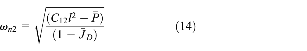
Natural frequencies (critical speeds) of the damp-free rotor system (8):

where

in case of
For numerical calculations using formulas (9) and (10), some geometric and dynamic parameters of the gyroscopic rotor system are borrowed from the experimental installation used in the works of Iskakov.6,8 These parameters are shown in Table 1.
Parameters of the gyroscopic rotary system.

Now it is possible to calculate the natural frequencies (critical speeds) of the gyroscopic rotor system (8): ω1 = 64.94 s−1, ω2 = 71.34 s−1.
The natural angular speed of the shaft rotation ω1 in the interval [64.95 s−1, 64.48 s−1] can be approximately considered constant and equal to ω1 = 65 s−1.This makes it possible to use ω1 in the process of reducing
Introduce the following dimensionless parameters:


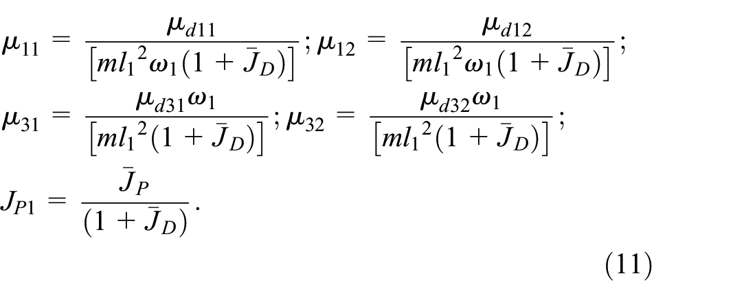
Using (11), the equations of motion (8) can be represented in dimensionless form:

where

- dimensionless natural frequency of the rotor system (12) at
- dimensionless natural frequency of the rotor system (12) at
Solving the equations of motion and frequency characteristics of a nonlinear rotor system with anisotropic elastic and damping characteristics
The values

where
In this case, the geometric center of the disk describes an ellipse with the following equation

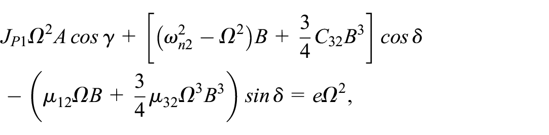
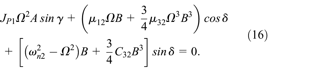
Substituting expressions (15) into system (12), using some trigonometric identities and equating only the coefficients for the functions


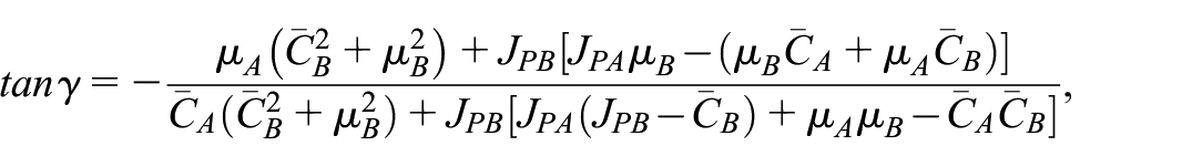
Introduce the following designations:


Taking into account (17), present the expressions for the amplitude-frequency characteristics:


and expressions for phase-frequency characteristics:

Non-stationary resonant oscillations of the rotor system
In the case of selecting the area of rotor operating speeds for their critical values, resonant transitions to these areas, and back when the motor is switched on and off, respectively, are not stationary.
To study non-stationary processes in a rotor system close to linear, use one of the asymptotic methods to solve the equations of motion (12), for example, slowly-changing amplitudes method (VAM).7,25 For the possibility of applying the slowly-changing amplitudes method, the following restrictions are accepted. The components of the moments of the damping forces
Equation (12), with small values

Equation (20) are a system of second order nonlinear ordinary differential equations with respect to
Since we want to investigate the forced fundamental resonant oscillations, we will look for solutions (20) at the frequency of the exciting moment:

where
Introduce new variables
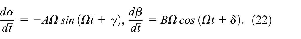
Expressions (22) are not the results of differentiation
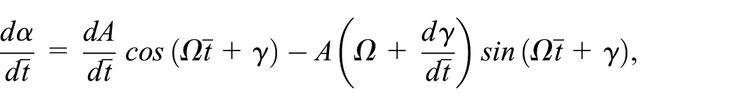

Therefore, in order to be consistent with expressions (22), it must be assumed that


These ratios can be considered as additional conditions imposed

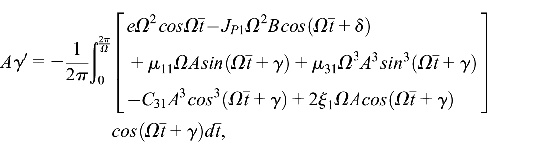
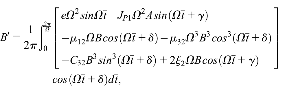

After performing the integration of equation (25), we come to a system of equations of non-stationary oscillations of the rotor


Under the conditions
By equations


To study the effect of stiffness anisotropy and damping of the elastic support on the rotor transient dynamics in the resonance region, following the method used in works,7,9,17–19,26 we obtain differential equations of rotor motion in a dimensionless compact form

where
Higher harmonics are suppressed by damping forces over time, and single-frequency oscillations of the basic harmonic develop in the system with a frequency close to the frequency of the disturbing force. 8
The single-frequency method makes it possible to consider a non-stationary resonant transition under very general conditions – causing the variability of the coefficients of differential equations, in the presence of nonlinearity of the restoring and damping characteristics of flexible supports. In fact, the law of change in the angular velocity of the rotor can be obtained only on the basis of processing the results of experimental studies of acceleration and deceleration of the machine. However, to determine the general nature of a non-stationary resonant transition, the single-frequency method allows solving the problem with an arbitrary law of variation in the angular velocity of the rotor. In this case, the angular velocity of the rotor should change slowly with respect to the values of the natural frequencies of the system under study.
Therefore, search for solutions (28) in the form:

Further, using the method of varying amplitude and proceeding as in the previous one, the equations of the transient process will be obtained in the form


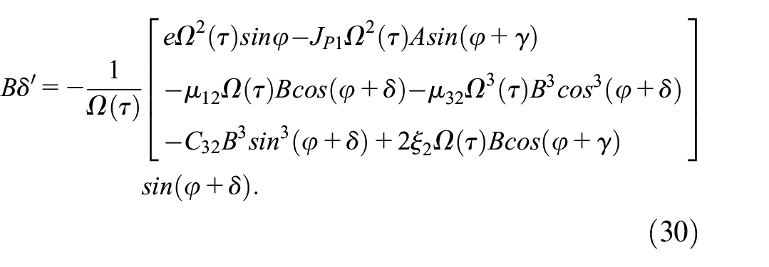
After averaging equation (30), a system of equations of a non-stationary process will be obtained


In equations (28), (30), and (31), the most commonly used form of representing the change in the angular speed of rotation of the shaft
Results
Stationary amplitude-frequency characteristics
Calculations by formulas (11), (13), and (14) give the following values of dimensionless parameters:
The results of the calculation according to formulas (9) are graphically presented in Figures 2 and 3. For a visual representation of the frequency response in the directions of oscillation, the values of the amplitude of oscillations A and B are deposited in orthogonal axes perpendicular to the axis of the angular velocity of the shaft Ω. From these graphs, two critical velocities and two resonance zones corresponding to the values of the linear characteristic of the support elasticity in two orthogonal directions are clearly visible. In the zone of each critical speed, there are two amplitude-frequency curves. The appearance of the second amplitude-frequency curve is associated with projections of a passive gyroscopic moment that connect both equations of rotor motion. The greater the value of the passive gyroscopic moment, the higher the peak amplitude of this curve. The area covered by the amplitude-frequency curve of the main direction is larger in size than that for the second direction. Increase in the value of the linear damping (Figures 2(a), (c), (e) and 3(a), (c), (e)) or values of geometrical nonlinearity of damping (with a constant value of linear damping; Figures 2(b), (d), (f) and 3(b), (d), (f)) in one of the directions suppresses the maximum resonance amplitudes of oscillations of this direction and oscillations of the perpendicular direction, but corresponding to this critical velocity. Comparison of Figure 2(b), (d), (f), with 2(a), (c), (e) and Figure 3(b), (d), (f) with 3(a), (c), (e) shows that geometrically nonlinearity of damping at a constant value of linear damping suppresses the peaks of the amplitude-frequency curves more significantly than linear damping. 27

Stationary amplitude-frequency characteristics at C31 = C32 = 0 for values: (a) μ11 = 0.01, 0.02, 0.04 and μ12 = 0.01; (b) μ31 = 0.01, 0.02, 0.04 and μ32 = 0.01; (c) μ11 = 0.01 and μ12 = 0.01, 0.02, 0.04; (d) μ31 = 0.01 and μ32 = 0.01, 0.02, 0.04; (e) μ11 = 0.01, 0.02, 0.04 and μ12 = 0.01, 0.02, 0.04; (f) μ31 = 0.01, 0.02, 0.04 and μ32 = 0.01, 0.02, 0.04.

Stationary amplitude-frequency characteristics at C31 = C32 = 0.1 for values: (a) μ11 = 0.01, 0.02, 0.04 and μ12 = 0.01; (b) μ31 = 0.01, 0.02, 0.04 and μ32 = 0.01; (c) μ11 = 0.01 and μ12 = 0.01, 0.02, 0.04; (d) μ31 = 0.01 and μ32 = 0.01, 0.02, 0.04; (e) μ11 = 0.01, 0.02, 0.04 and μ12 = 0.01, 0.02, 0.04; (f) μ31 = 0.01, 0.02, 0.04 and μ32 = 0.01, 0.02, 0.04.
The graphs in Figure 3 show that with linear stiffness irregularities in orthogonal directions and the presence of a nonlinear rigid characteristic of the support in both directions, the amplitude-frequency curves of the main directions have four jumping effects (the figures show two jumping effects corresponding to the direction of the rotor speed increasing). They can be more effectively eliminated with an increase in the value of the geometric nonlinearity of damping (with a constant value of linear damping; Figure 3(b), (d), (f)) compared to linear damping (Figure 3(a), (c), (e)). The absence of jump transitions in the second amplitude-frequency curve is explained by the fact that it is located in a region with a large value of geometric nonlinearity of damping, where there are no jump effects, but the influence of the nonlinear rigid characteristic of the support remains. With an increase in the projection of the passive gyroscopic moment toward the projection of the inertia moment, jump effects may appear in the second resonance curve. It is known that with the isotropy of the linear elastic characteristic of the support, the amplitude-frequency curve can have only two jumping effects corresponding to one critical speed.
When the values of the nonlinear rigid characteristic of the support differ, the slopes of the amplitude-frequency curves of the main directions are different depending on these values.
The reliability of the obtained results is confirmed by a good agreement of the results of the analytical solution and the numerical solution of the equations of the rotor motion (12; see Figure 4) and suppression of the amplitudes of variations of angular coordinates constructed by direct modeling, geometrically by nonlinearity of damping at a constant value of linear damping (see Figure 5). Comparison of analytical and numerical solutions of equation (12) is made at the following parameters: Ω = 1.0067; C31 = C32 = 0; μ31 = 0.01, 0.02, 0.04; μ32 = 0.01; μ11 = μ12 = 0.01.

Analytical and numerical solutions of equation (12) by

Numerical solutions of equations (12) by (a):
Non-stationary amplitude-frequency dependencies
In the case of a slow increase in the angular velocity of the shaft with ν = 0.00025 and

Non-stationary amplitudes depending on the vibration frequency at ν = 0.00025 and C12 = C32 = 0 for values: (a) μ11 = 0.01, 0.02, 0.04 and μ12 = 0.01; (b) μ12 = 0.01, 0.02, 0.04 and μ32 = 0.01; (c) μ11 = 0.01 and μ12 = 0.01, 0.02, 0.04; (d) μ12 = 0.01 and μ32 = 0.01, 0.02, 0.04; (e) μ11 = 0.01, 0.02, 0.04 and μ12 = 0.01, 0.02, 0.04; (f) μ12 = 0.01, 0.02, 0.04 and μ32 = 0.01, 0.02, 0.04.

Non-stationary amplitudes depending on the vibration frequency at ν = 0.00025 and C31 = C32 = 0.1 for values: (a) μ11 = 0.01, 0.02, 0.04 and μ12 = 0.01; (b) μ31 = 0.01, 0.02, 0.04 and μ32 = 0.01; (c) μ11 = 0.01 and μ12 = 0.01, 0.02, 0.04; (d) μ31 = 0.01 and μ32 = 0.01, 0.02, 0.04; (e) μ11 = 0.01, 0.02, 0.04 and μ12 = 0.01, 0.02, 0.04; (f) μ31 = 0.01, 0.02, 0.04 and μ32 = 0.01, 0.02, 0.04.
With a slow decrease in the angular speed of the shaft with ν = −0.00025 and

Non-stationary amplitudes depending on the vibration frequency at ν = -0.00025 and C31 = C32 = 0 for values: (a) μ11 = 0.01, 0.02, 0.04 and μ12 = 0.01; (b) μ31 = 0.01, 0.02, 0.04 and μ32 = 0.01; (c) μ11 = 0.01 and μ12 = 0.01, 0.02, 0.04; (d) μ31 = 0.01 and μ32 = 0.01, 0.02, 0.04; (e) μ11 = 0.01, 0.02, 0.04 and μ12 = 0.01, 0.02, 0.04; (f) μ31 = 0.01, 0.02, 0.04 and μ32 = 0.01, 0.02, 0.04.

Non-stationary amplitudes depending on the vibration frequency at ν = -0.00025 and C31 = C32 = 0.1 for values: (a) μ11 = 0.01, 0.02, 0.04 and μ12 = 0.01; (b) μ31 = 0.01, 0.02, 0.04 and μ32 = 0.01; (c) μ11 = 0.01 and μ12 = 0.01, 0.02, 0.04; (d): μ31 = 0.01 and μ32 = 0.01, 0.02, 0.04; (e) μ11 = 0.01, 0.02, 0.04 and μ12 = 0.01, 0.02, 0.04; (f) μ31 = 0.01, 0.02, 0.04 and μ32 = 0.01, 0.02, 0.04.
Thus, in summary it can be said that the enhancement of linear damping with geometrically nonlinear damping is one of the effective methods of control (management) of resonant amplitudes to ensure smooth resonant transitions.
The study of the effect of anisotropy of the properties of the support material on the dynamics of the experimental rotor
Experimental work on the study of the effect of the anisotropy of the restoring and damping characteristics of the support on the dynamics of the gyroscopic rotor of the centrifuge was carried out on an experimental installation, the general view of which is shown in Figure 10, and the layout of the elastic damping inserts is shown in Figure 11.

General view of the experimental rotor: 1 – rotor bowl, 2 – ZET 701 probes, 3 – elastic support, 4 – housing, 5 – electric motor in the casing, 6 – control stand, 7 – platform, 8 – eddy current displacement sensor ZET 7140-S, 9 – measuring line connector, 10 – ZET 7174 interface converter, 11 – UNI-T UT372 tachometer, 12 – laptop.

The design of the elastic support (a) from the hexagon: 1 – rubber plate (BMS or HFAAR), 2 – coupling, 3 – rotor shaft, 4 – bearing and (b) quadrilateral: 5 – viscoelastic tab of HIPS brand (high impact polystyrene), 6 – viscoelastic tab of BFLEX brand.
The installation consists of the main elements: the rotor bowl, the shaft, the drive motor, the lower cardan and upper elastic support, and the housing attached to the platform. The rotor is made in the form of a cylindrical bowl to satisfy the condition
To measure the amplitude of the transverse movement of the shaft, ZET 701 probes are installed on the housing, which are connected to eddy current displacement sensors ZET 7140-s, and those in turn are connected to the connector of the measuring lines ZET 7001-P, then to the converter of the ZET 7174 interface. The interface converter is connected to the computer. The tachometer UNI-T UT372 is used to measure the speed.
The values of the parameters of the constituent elements of the experimental rotor design are shown in Table 2.
Parameters of the structural elements of the experimental rotor.

The ZetLab vortex sensor program and the UT372 tachometer program are involved. The results of the experimental work are reflected in the ZETLAB program. Processing of the obtained measurement data is carried out in the MATLAB program. Experimental amplitude-frequency characteristics of a gyroscopic rotor with an elastic hexagon support are shown in Figures 12 and 13. Damping inserts-plates are made of BMS rubber and HFAAR rubber.

Experimental amplitude-frequency curves with an increase in the speed of rotation of the gyroscopic rotor in different versions of the support material: X1– from BMS grade rubber, X2– from HFAAR grade rubber.

Experimental amplitude-frequency curves with a decrease in the angular velocity of the gyroscopic rotor in different versions of the support material: X1– from BMS grade rubber, X2– from HFAAR grade rubber.
With the increasing speed of rotation of the shaft over time in the mode (Figure 12) and the change of the viscoelastic support plate grade it is easy to notice a more damping effect of the HFAAR grade compared to the BMS grade. The maximum resonance amplitude decreases from 1.248 to 1.168 mm. After the resonance region 217.8–800 s−1, the amplitude decreases at the end of the interval from a value of 1.139 mm to a value of 1.080 mm. Taking into account the results of References 1–10, it remains to assume that the suppression of the amplitude of the resonant and after the resonant oscillations of the frequency response of the experimental rotor is the result of the influence of only geometrically nonlinear damping. In the case of acceleration of the rotor, its critical speed is 102.2 s−1 for the BMS rubber grade, 124.4 s−1 for the HFAAR rubber grade (Figure 12). In case of slowing down, the critical rotor speed is 290.9 s−1 for the BMS rubber grade, 277.3 s−1 for the HFAAR rubber grade (Figure 13). The experimental values of the critical velocities practically coincide with the analytically found values according to formula (11) from the work 8 :

The difference in the values of the critical rotor speed in during acceleration and deceleration is explained as in the article by Bharti et al. 28 by the asymmetry of support stiffness and shaft flexibility. When running out in the zone 800–386.4 s−1 below the resonance, the amplitude of oscillations decreases from 1.139 to 1.080 mm, as when running up in the zone below the resonance, and the maximum resonance amplitude from 1.232 to 1.145 mm. The amplitude of oscillations at critical run-out speeds is lower than at run-up. 28 When running out, jumps are observed in the resonance zone, which indicate the existence of a nonlinear rigid characteristic of the support. Comparison of resonance curves in Figures 12 and 13 prove the asymmetry of nonlinear stiffness in opposite directions.
Figure 14 shows an experimental resonance curve and an analytically constructed amplitude-frequency characteristic of the rotor at direct stroke for the HFAAR rubber grade of the elastic support. The analytical resonance curve at c3= 0 is constructed according to the formula


Graphs of the experimental resonance curve (1) and analytical frequency response (2) with a direct stroke for the HFAAR rubber grade elastic support.
By the points of intersection of experimentally and analytically constructed frequency characteristics, the values of linear damping and geometric nonlinearity are approximately determined: μd1 = 22.60 N m s, μd3 = 1422.9 N m s3.
Figure 14 shows a good agreement between the amplitude-frequency curves obtained by experimental and analytical studies in the resonance zone, the differences in the results before and after the resonance zones are about a tenth of a millimeter. As is known, the width of the resonance curve Δω, in those places where the amplitude of the oscillations is
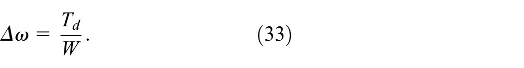
It follows from formula (33) that the width of the resonance curve
Models and exact values of linear and nonlinear damping are usually determined as a result of their identification, which is a separate research topic.
The anisotropy of stiffness and damping in two orthogonal directions was created by placing in two opposite cells of the tetrahedron (octahedron) of impact-resistant polystyrene HIPS, in the other two flexible soft material BFLEX perpendicular to the previous cells. Experimental amplitude-frequency response for the directions x(α) and y(β) are shown in Figure 15. The first critical velocity is ∼31.8 s−1, the second critical velocity is ∼318.2 s−1. For the first critical velocity, the direction x(α) is principal, and for the second critical velocity, the direction y(β) is principal. Therefore, the amplitude of oscillations of the direction x(α) at the first critical speed is greater than the same amplitude at the second critical speed, the amplitude of oscillations of the direction y(β) at the first critical speed is less than the same value at the second critical speed. The difference between the maximum resonance values of the amplitude of oscillations of one direction is not very large, due to the influence of the significant values of the projections of the passive gyroscopic moment. Jumps are observed in the resonant regions, which confirm the existence of a rigid nonlinear characteristic of the support elasticity. In the first resonance region, jumps occur from large amplitude and a lower speed of rotation to smaller amplitude and a large speed of rotation, and in the second resonance region, jump transitions are carried out from a smaller amplitude and speed of rotation to a large amplitude and speed of rotation of the shaft. This proves the anisotropy of the nonlinear stiffness of the material of the elastic support: if in the direction x(α) the nonlinear elasticity of the support has a rigid characteristic, then in the direction y(β) it has a soft characteristic. The manifestation of damping anisotropy, including geometric nonlinear in the region behind the critical rotation speeds, is more significant than in the region between the critical rotation speeds of the shaft.
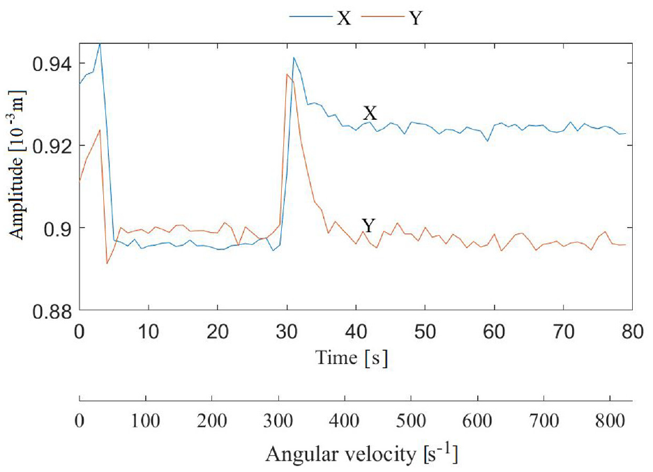
Resonance amplitude-frequency characteristics with increasing rotation speed of the gyroscopic rotor and anisotropy of elastic damping properties of the support material in mutually perpendicular directions: X(α) and Y(β).
Based on the results of the research carried out in this work, and using 7 3D models and the prototype developed in the work of Iskakov et al. (Figure 10) and the structure of the elastic support of the gyroscopic rotor (Figure 11) a patent was obtained for the invention of a centrifuge based on a gyroscopic rotor. 29 In the proposed support design (Figure 11), the change in the number and combination of the arrangement of inserts with different viscoelastic properties can be adjusted (controlled) by the stiffness and damping of the support. The operating speed range of the machine can be determined by the critical speed(s). In this case, the viscoelastic materials for the inserts are selected in such a way that their elastic and damping properties helped the rotor smoothly pass through the critical speed(s) and avoid the jump effect in the resonance curve(s) arising under the influence of the nonlinear elastic characteristic of the inserts.
Conclusions
Differential equations of motion of the gyroscopic rotor are constructed taking into account the anisotropy of the elastic and damping properties of the support material and are solved analytically by the method of harmonic balance, convenient for obtaining separately frequency characteristics of oscillations of orthogonal directions. When obtaining equations of non-stationary oscillations, the method of changing amplitudes is used.
In the case of different linear stiffness of the elastic support material in two orthogonal directions, two critical velocities and the corresponding resonance zones are observed. In the zone of each critical speed, there are two amplitude-frequency curves of oscillations of the main direction and the direction perpendicular to it caused by the action of the projection of the passive gyroscopic moment.
In the case of a nonlinear rigid characteristic of the support elasticity, the amplitude-frequency curves of the main directions are accompanied by jump transitions.
An increasing in the geometrical nonlinearity of damping with the constant linear component suppresses the resonant amplitudes of oscillations of each direction more significantly than the linear component.
Enhancement of linear damping with geometrical nonlinearity of damping is one of the effective methods of controlling the resonant amplitudes, providing smooth resonant transitions.
Comparison of analytical solutions and the results of direct modeling of the equations of rotor motion show good agreement between them.
The effects of the anisotropy of the elastic and damping properties of the elastic support material on the dynamics of the gyroscopic rotor have been experimentally investigated.
The results of the studies performed can be used in scientific research and design calculations for creation of supports with the best elastic and damping parameters for a vibrating gyroscopic rotary machine.
Footnotes
Handling Editor: Aarthy Esakkiappan
Declaration of conflicting interests
The author(s) declared no potential conflicts of interest with respect to the research, authorship, and/or publication of this article.
Funding
The author(s) disclosed receipt of the following financial support for the research, authorship, and/or publication of this article: This research has been/was/is funded by the Science Committee of the Ministry of Science and Higher Education of the Republic of Kazakhstan (Grant No. AP15473701, BR20280990).