
Abstract
Due to cylinder friction, valve dead zone effect, flow nonlinearity, and measurement noise exist in pneumatic system. In the actual machining, it is difficult to achieve precise control of the pneumatic servo polishing system using the traditional PID algorithm, so the machining accuracy of the blades cannot be guaranteed. A sliding mode control (SMC) method based on high gain observer (HGO) is proposed. The HGO observes the output signal of the system and feeds the estimated signal back to the SMC to ensure that the observation error is uniform ultimate boundedness. Simulation and experiments show that compared with the PID algorithm, the steady-state error of HGO-SMC can be reduced by 66.4%. Compared with SMC(sgn), the high-frequency chattering of HGO-SMC can be reduced by 72.5%. Moreover, the polishing processing experiment shows that HGO-SMC can improve the form and position accuracy by 52.6% and reduce the surface roughness by 55.6%, compared with the original PID control algorithm of the polishing machine tool.
Introduction
Blades are complex curved surface parts, which are widely used in aerospace, ships, and other fields.1–4 The working environment of the blade is extremely complex. It is required to bear strong mechanical centrifugal force and aerodynamic force, overcome extremely strong heat load and vibration load, and have strong corrosion resistance and abrasion resistance. Since there are still some machining tool marks on the surface of the blade after finishing, the quality is far from meeting the use requirements, which seriously affects the fatigue strength and service life of the blade. Generally, the polishing process is used to ensure that the surface roughness, residual stress, and surface structure of the blade meet the actual engineering needs.5–8 The difficulty in the polishing process of curved surface parts is to maintain a stable pressure on the contact point and remove the residue evenly. Therefore, the selection and control of polishing force is very important.
The polishing force control system is a nonlinear aerodynamic system susceptible to interference. Using traditional PID control strategy can not achieve high-precision control of blade polishing force. In the process of blade polishing, polishing force is a very critical process parameter, which has been paid more and more attention by researchers, especially the control strategy of polishing force. Due to the non-linear problems such as the dead zone characteristic of proportional valve, cylinder friction, and gas compressibility in pneumatic system, a second-order linear PID self anti-interference controller is proposed, which can skip the dead zone after compensation through linear PID feedback control law. 9 In literature, 10 a gravity compensation algorithm is proposed to eliminate the interference of workpiece gravity on the constant force polishing control system. The hybrid force/position active flexible control algorithm of robot is established, the force control model based on least square parameter identification is proposed, and the constant control of polishing force is realized based on Fuzzy PID control strategy. In literature, 11 a pneumatic polishing force control system is designed to achieve reliable and stable polishing force control. The polishing force is controlled in real time by the PWM signal generated by PLC. The PID control algorithm with moving average filter is designed in the PLC, which improves the dynamic performance of the system. In literature, 12 under the condition of strong vibration interference, the motor encoder and joint torque sensor are used to detect and control the robot polishing contact force. The extended state observer is used to estimate the contact force in real time, and the adaptive filter is designed by combining the notch filter and tracking differentiator.
In literature, 13 in order to ensure the stability of the robot polishing contact force, a robot impedance control parameter learning algorithm based on reinforcement learning is proposed. By combining the dynamic matching method and the linearization method to predict the output distribution of the state, the impedance parameters of the optimal strategy are obtained. In literature, 14 during the robot abrasive belt polishing process, the adaptive weighted particle swarm optimization algorithm is used to optimize the input shaper and realize parameter self-tuning. The controller achieves a smooth transition between blade grinding and polishing processes, effectively shortening the system stabilization time and reducing the maximum overshoot. In literature, 15 due to the problems of low output force, poor control accuracy, and slow dynamic response of the force control end effector of industrial robots, a pneumoelectric force-controlled end-effector coordinated control method based on impedance control is proposed. Compared with the pneumatic end effector, the end effector has the advantages of high precision of polishing force control, fast dynamic response, and small overshoot. In literature, 16 in order to ensure the active flexible motion of robot, a hybrid control strategy of polishing robot based on adaptive impedance control is proposed to reduce the impact caused by machining contact. Simulation and experimental results show that the control strategy can ensure that the motion curve is consistent with the surface topography of the workpiece, enabling more accurate position tracking and polishing force tracking. In literature, 17 in order to improve the polishing quality of complex surfaces by polishing robot and ensure the constant polishing force in the process of machining, a real-time adjustment of spindle speed according to the vector direction of the machined surface is proposed. After finishing polishing trajectory planning, the robot corrects the trajectory along the normal vector direction of the machined surface by combining the feedback signal of the sensor and the PI controller, and indirectly realizes polishing force control. In literature, 18 based on the dynamic input-output model of the pneumatic polishing force control system, and for the non minimum phase system, a new integral sliding mode controller is proposed, which is composed of equivalent control and switching control. Simulation and experiments show that the proposed controller can effectively suppress the external disturbance and model uncertainty of nonlinear pneumatic system. Compared with the traditional PID controller and RST controller, the control accuracy of polishing force has been significantly improved.
Due to the obvious dead time characteristics, friction characteristics, and relay characteristics of the strong nonlinear control system, the traditional PID control strategy is difficult to achieve the desired control effect.19–22 Due to the sliding mode control algorithm has strong robustness, fast response, and no need for system online identification, which has a good control effect for nonlinear systems. However, when the state trajectory reaches the sliding mode surface, it will cross back and forth on both sides of the sliding mode surface and then approach the equilibrium point, resulting in high-frequency buffeting.23–27 Switching gain reduction, dynamic sliding mode, filtering, and saturation function can effectively reduce high-frequency chattering of sliding mode control, but it increases the steady-state control error and improves the design difficulty of the controller.28–30
In recent years, many researchers have applied intelligent control technology to practical projects and achieved good control effect. In literature, 31 an adaptive fuzzy sliding mode controller based on Kalman filter is proposed. An adaptive fuzzy logic algorithm is designed to approximate the parameters of the sliding mode controller to avoid real-time high-frequency chattering, and Lyapunov theory is used to prove the stability of the system. In literature, 32 an internal model control based on inverse system theory is proposed to overcome multivariable coupling, nonlinearity, and pure delay of the system. The simulation results show that the combination of internal model control and PID has stronger robustness, higher control accuracy, and easier adjustment of control parameters. In literature, 33 in order to reduce the influence of unknown parameters on the control system, neural network technology is used to approximate the unknown nonlinear term in the controller design process. Lyapunov theory is applied to ensure that all signals in the closed loop system are uniformly ultimately bounded, and the system attitude is synchronized with the desired trajectory. In literature, 34 a nonsingular terminal sliding mode control based on genetic algorithm and particle swarm optimization algorithm is proposed to solve the vibration problem of nonlinear fully coupled systems, which can overcome the uncertainty of system variables and external disturbances.
In this paper, the force of polishing structure is analyzed and the polishing force calculation model is established. An adaptive sliding mode control based on high gain observer is designed, which does not require the system state to be measurable, and can estimate the system state through the high gain observer to ensure that the observation error is uniformly ultimately bounded.
Rest parts of this paper are organized as follows: the CNC polishing machine tool structure is introduced in Section “CNC polishing machine.” In Section “Mathematical model of polishing force calculation,” mathematical model of polishing force calculation is established. Nonlinear dynamics model of polishing force control system is established in Section “Nonlinear dynamics model of polishing force control system.” HGO-SMC is designed in Section “HGO-based SMC.” Simulation and experimental analysis of the proposed HGO-SMC is carried out in Section “Simulation and experimental analysis.” Section “Conclusion” is the conclusion.
CNC polishing machine
In order to carry out abrasive belt polishing process experiment, we have developed a five-axis CNC polishing experimental platform. The main structure of the machine tool is shown in Figure 1, which includes machine bed, column, spindle mechanism, five servo motion axes, and auxiliary equipment. The control system of the polishing machine is mainly composed of numerical control system, servo control system, and industrial control computer. The numerical control system is used to calculate the relative motion trajectory of abrasive belt-wheel and the blade, the servo control system is used to realize the precision control of five motion axes, and the industrial control computer is mainly used for the parameter control of abrasive belt-wheel. The motion parameters of the CNC polishing machine is shown in Table 1, and schematic diagram of polishing force control system is shown in Figure 2.

CNC polishing experimental platform.
Motion parameters of CNC.


Schematic diagram of CNC polishing experimental platform.
Mathematical model of polishing force calculation
The polishing structure and stress of the abrasive belt-wheel series is shown in Figure 3. The abrasive belt-wheel series is composed of drive wheel, contact wheel, and abrasive belt. The driving wheel is mounted on the frame of the polishing structure and can rotate and move in the vertical direction relative to the frame. The contact wheel is rigidly connected with the polishing structure and can only rotate around the center. The whole polishing structure is installed on the CNC machine tool and can only move up and down under the pressure of the polishing cylinder. The air cylinder and hydraulic motor act on the driving wheel to make the abrasive belt tension, and the contact wheel is driven by the abrasive belt

Stress of the abrasive belt-wheel series.
During blade polishing, mechanical relationship of the whole polishing structure can be expressed as follows:

where
To study the deformation of the contact wheel caused by the belt tension, which is necessary to analyze the actual force on the contact part between the contact wheel rubber and the abrasive belt. 35 The radial contact pressure between the abrasive belt and the contact wheel can be derived by the equilibrium equation (2).
where
Deformation problem of contact wheel caused by abrasive belt tensioning can be considered as deformation of a plane elastic thick walled cylinder under non-uniform contact stress. Stress boundary condition can be expressed as follows:

where
When the abrasive belt is under tension, the stress in the rubber layer of the contact wheel can be written as follows:
It is not only necessary to consider the deformation of rubber contact wheel caused by tension but also study main body deformation position of contact wheel, abrasive belt, and blade. Assuming that all contact parts are isotropic elastic materials, the contact problem can be simplified as a spring system, as shown in Figure 4. When the contact stress acts on the spring system, the strain relationship between each layer can be expressed as follows:

where

Schematic diagram of contact part simplified as a spring system.
Mooney-Rivlin is the most widely used constitutive model for nonlinear elastomers such as rubber, the stress-strain equation can be written as follows:

Where
Deformation analysis of contact part is shown in Figure 5, the contact wheel radius at point Q can be expressed as follows:
where

Schematic diagram of deformation analysis of contact part.
According to the thickness of the outer rubber, the thickness of the rubber layer at point Q can be calculated by equation (8).

The deformation thickness of the rubber layer in the Y-axis direction can be calculated by equation (9).

where
The deformation thickness of the rubber layer in the x-axis direction can be calculated by equation (10).

The contact stress can be calculated by equation (11)

The pressure on a single section can be expressed as follows:
Total contact pressure can be written as follows:
Equation (13) is the calculation model of the polishing force, which indicates that the polishing force applied on the blade profile should be time-varying. The time-varying polishing force is used for blade machining, which requires higher control accuracy, dynamic characteristics, and robustness of the polishing force control system.
Nonlinear dynamics model of polishing force control system
The polishing force control system is shown in Figure 6, which is mainly composed of air compressor, electromagnetic reversing valve, proportional valve, cylinder, pressure sensor, IPC, D/A conversion device, power amplifier, and servo driver. The IPC is used as a system controller to calculate and process feedback signals and send control signals to the actuator. The system can indirectly adjust the gas flow into the cylinder by controlling the proportional valve, so that the polishing force can be controlled in real time.

Schematic diagram of polishing force control system.
If cylinder, piston, and load are considered as a whole, the balance equation can be established as follows:

where
According to Newton’s second law, the balance equation of proportional valve spool can be obtained.

where
In general, the ideal gas in the pneumatic system can be calculated by the Sanville equation and can be linearized into equation (16).
where
Assume that the cylinder is at a constant temperature, equation (17) can be derived from the first law of thermodynamics and the mass flow conservation equation.

where
According to (16) and (17), then
where
By Laplace transformation of equations (14)–(18), the transfer function of polishing force control system can be derived as follows:
where
HGO-based SMC
The high-gain observer can estimate the state asymptotically according to the measurement results, and can be designed separately from the state feedback controller. Equation (19) can be written as follows:

where
Since

For a second-order system, it is complicated to design the controller only by output.

Where
Set

When
According to equations (21) and (23), the following can be obtained:

Then
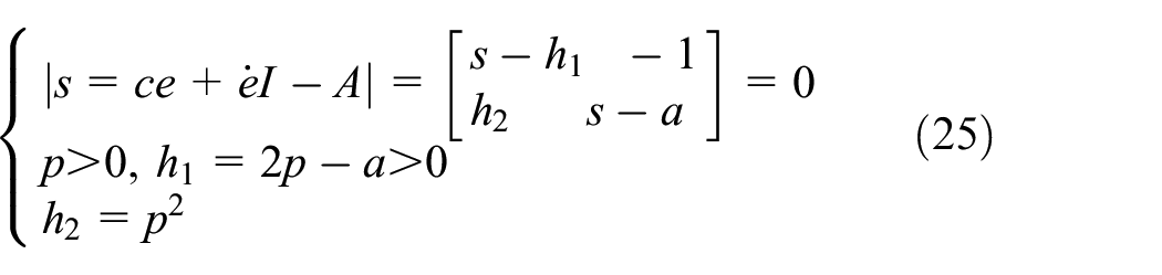
Set the value of
According to equations (24) and (25), the exponential convergence of

where ϕ0 and σ0 are positive constant.
The characteristic equation of matrix

where
According to equations (22)–(27), then

For equation (20), the sliding mode function is designed as follows:

where

The Lyapunov function of SMC is designed as follows:

Due to

Then

where
And

where
Since

The Lyapunov function of the closed-loop system is as follows:

where
Since the observer converges exponentially, then

where
Theorem 1 for

where a is arbitrary constant.
According to equations (36) and (37), then

So
According to the above equation, the overall control diagram of the polishing force system is shown in Figure 7.
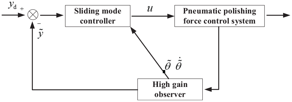
Control diagram of the polishing force system.
Simulation and experimental analysis
Using MATLAB and C++ to compile the simulation program, which is based on HGO-SMC and dynamic model of pressure control system. Set polishing force tracking control signal
Simulation results of square wave response are shown in Figures 8 to 12, and Simulation results of sinusoidal response are shown in Figures 13 to 17. The simulation results of square wave response and sine response of PID algorithm are shown in Figures 8 and 13, and the average value of control error is 5.04 N. Compared with other four control algorithms, PID algorithm has the largest control error.
Square response simulation with PID: (a) control error and tracking response and (b) control input.

Square response simulation with SMC (sgn): (a) control error and tracking response and (b) control input.

Square response simulation with SMC (sat φ = 0.02): (a) control error and tracking response and (b) control input.

Square response simulation with SMC (sat φ = 0.05): (a) control error and tracking response and (b) control input.

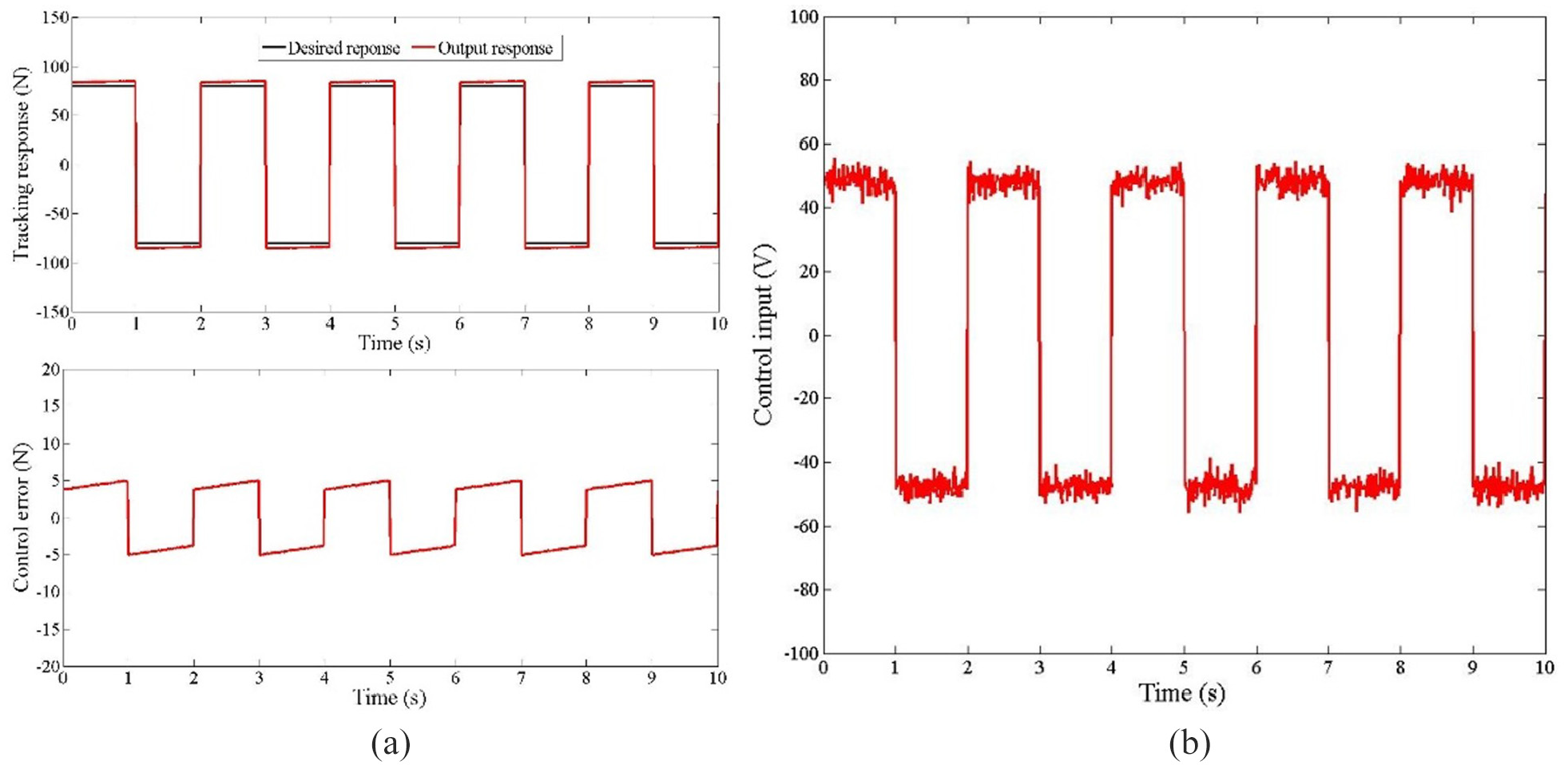
Square response simulation with HGO-SMC: (a) control error and tracking response and (b) control input.

Sine response simulation with PID: (a) control error and tracking response and (b) control input.

Sine response simulation with SMC (sgn): (a) control error and tracking response and (b) control input.
Sine response simulation with SMC (sat φ = 0.02): (a) control error and tracking response and (b) control input.

Sine response simulation with SMC (sat φ = 0.05): (a) control error and tracking response and (b) control input.

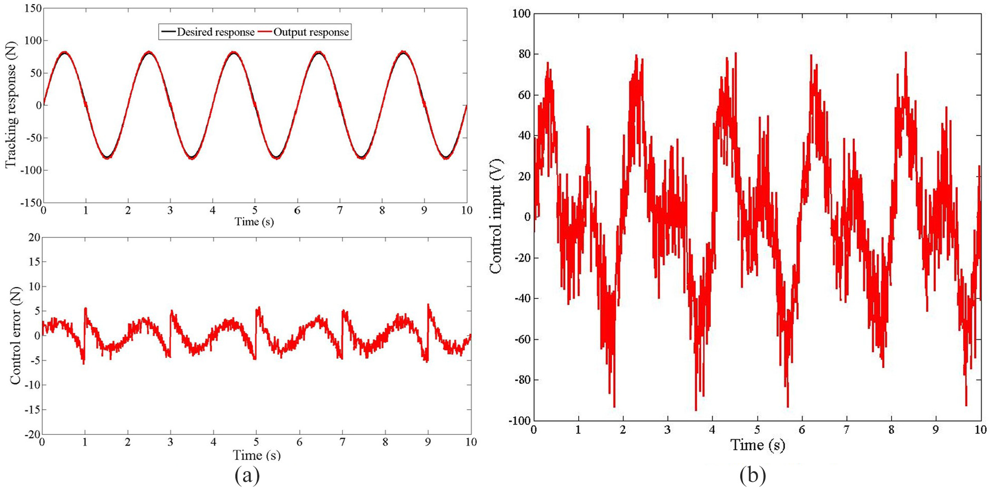
Sine response simulation with HGO-SMC: (a) control error and tracking response and (b) control input.
The simulation results of square wave response and sinusoidal response of the SMC with sgn algorithm are shown in Figures 9 and 14, with an average control error of 2.48 N. Compared with PID control algorithm, the control error of SMC with sgn algorithm is obviously reduced. However, from the aspect of control input, SMC with sgn algorithm is easy to generate high-frequency chattering, which not only affects the accuracy of control, increases energy consumption, causes system oscillation or instability, and damages controller components. SMC with sat(s) algorithm is proposed to reduce high-frequency chattering caused by SMC with sgn. Figures 10 and 15 show the simulation results of square wave response and sinusoidal response of the SMC with sat(0.02) algorithm, with an average control error of 3.385 N. SMC with sat(0.02) algorithm effectively reduces high-frequency chattering, but the average control error does increase. Figures 11 and 16 show the simulation results of square wave response and sinusoidal response of the SMC with sat(0.05) algorithm, with an average control error of 3.97 N. Compared with SMC with sat(0.02) algorithm, SMC with sat(0.05) algorithm has larger control error and smaller high-frequency chattering. According to the simulation results, when the boundary layer of SMC with sat(s) is thicker, the control error of the system increases and the high-frequency chattering decreases. Figures 12 and 17 show the simulation results of square wave response and sinusoidal response of the HGO-SMC algorithm, with an average control error of 1.225 N. Compared with PID, SMC with sgn, SMC with sat(0.02), and SMC with sat(0.05), the control errors of HGO-SMC algorithm are reduced by 75.7%, 50.6%, 63.8%, and 69.1% respectively, and the high-frequency chattering of the system is also significantly reduced.
The polishing experiment uses Advantech IPC- 610L as the controller, and the control program is written based on C++ language, including SMC program based on HGO, D/A program, sampling time sequence, and pressure sensor measurement program. Advantech PCL818L data acquisition card, PCL730 isolated digital I/O card, PCL726D/A analog output card are used for data acquisition, conversion, and output. Display, process, and analyze the collected data through LabWindows/CVI. After feedback, the IPC sends out command signals to control the pneumatic servo system, and finally realizes the real-time adjustment of polishing force.
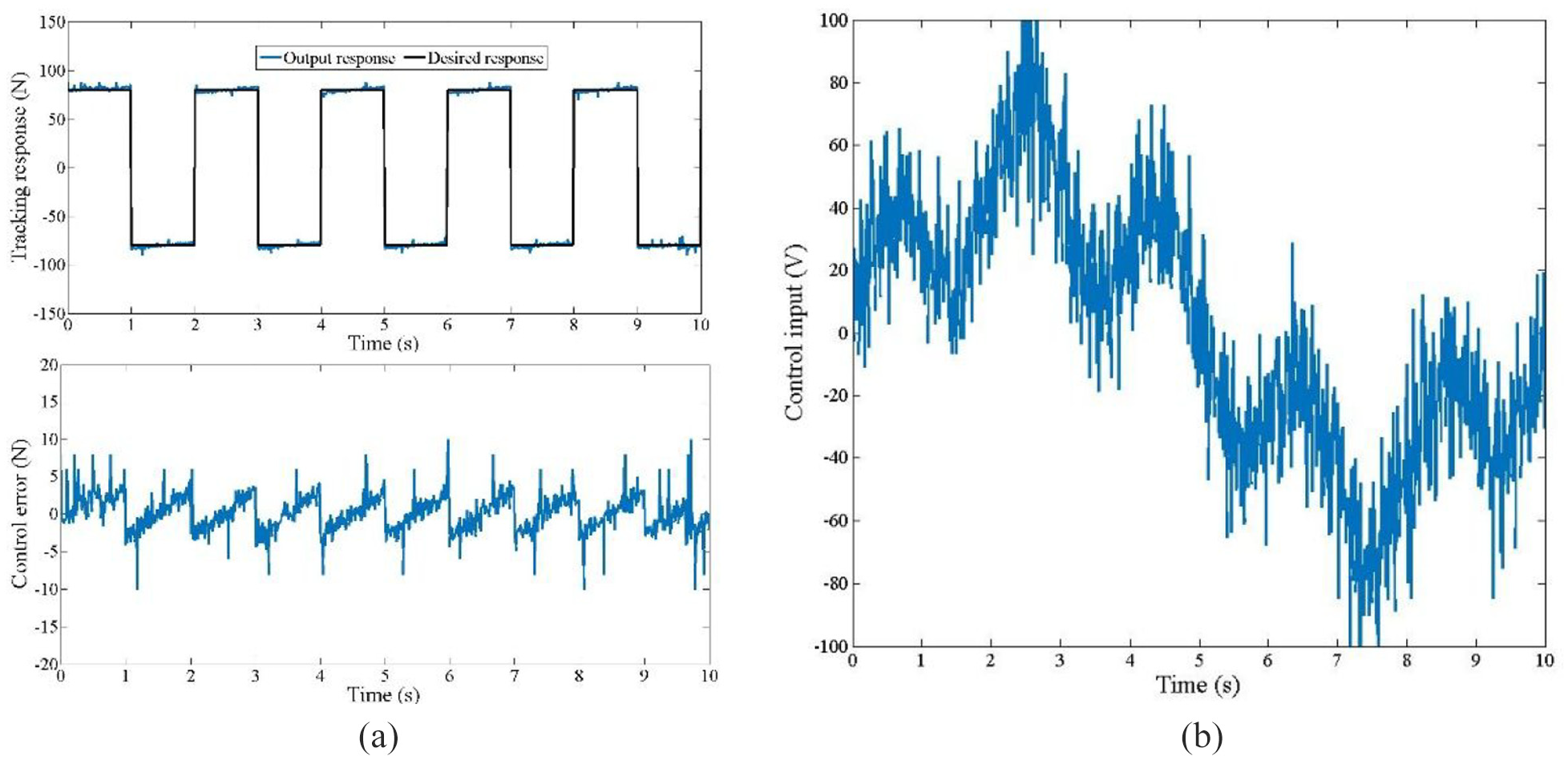
Experimental results of square wave response are shown in Figures 18 to 22, and experimental results of sinusoidal response are shown in Figures 23 to 27. Figures 18 and 23 show the experimental results of square wave response and sinusoidal response of the PID algorithm, with an average control error of 5.51 N. Figures 18 and 23 show the experimental results of square wave response and sinusoidal response of the SMC with sgn algorithm, with an average control error of 3.025 N.

Square response experiment with PID: (a) control error and tracking response and (b) control input.

Square response experiment with SMC (sgn): (a) control error and tracking response and (b) control input.
Square response experiment with SMC (sat φ = 0.02): (a) control error and tracking response and (b) control input.

Square response experiment with SMC (sat φ = 0.05): (a) control error and tracking response and (b) control input.
Square response experiment with HGO-SMC: (a) control error and tracking response and (b) control input.

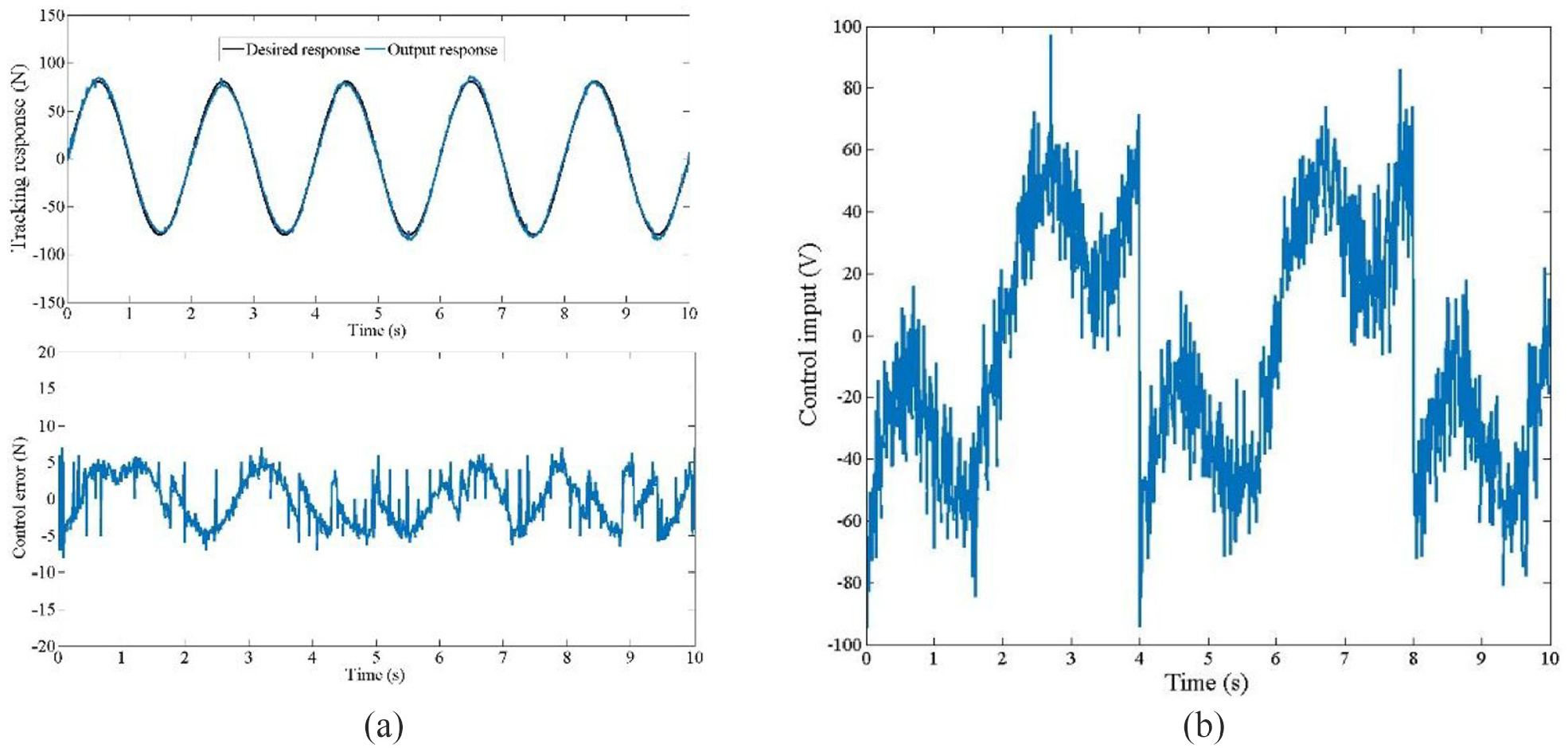
Sine response experiment with PID: (a) control error and tracking response and (b) control input.

Sine response experiment with SMC (sgn): (a) control error and tracking response and (b) control input.

Sine response experiment with SMC (sat φ = 0.02): (a) control error and tracking response and (b) control input.
Sine response experiment with SMC (sat φ = 0.05): (a) control error and tracking response and (b) control input.
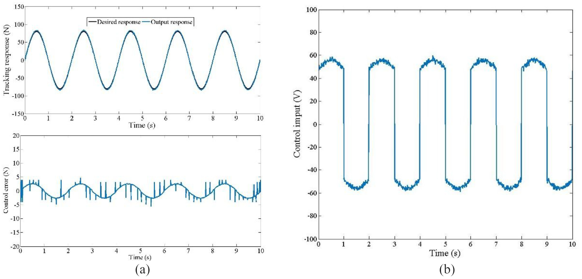
Sine response experiment with HGO-SMC: (a) control error and tracking response and (b) control input.
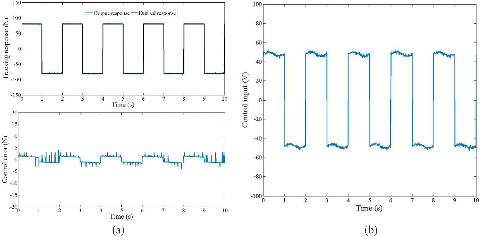
Figures 20 and 25 show the experimental results of square wave response and sinusoidal response of the SMC with sat(0.02) algorithm, with an average control error of 3.72 N. Figures 21 and 26 show the experimental results of square wave response and sinusoidal response of the SMC with sat(0.05) algorithm, with an average control error of 3.345 N. Figures 22 and 27 show the experimental results of square wave response and sinusoidal response of the HGO-SMC algorithm, with an average control error of 1.85 N. Compared with PID, SMC with sgn, SMC with sat(0.02), and SMC with sat(0.05), the control errors of HGO-SMC algorithm are reduced by 66.4%, 38.9%, 50.3%, and 44.7% respectively. To further verify the robustness of HGO-SMC, a 20 N interference signal was applied at t = 2.5 s. Figure 28 show that HGO-SMC has strong anti-interference ability.

HGO-SMC anti-interference verification: (a) square wave anti-interference simulation response, (b) square wave anti-interference experimental response, (c) sine anti-interference simulation response, and (d) sine anti-interference experimental response.
Analyzing the experimental results of square wave response and sinusoidal response, it can be found that the experimental results and simulation results of different control algorithms have the same change trend. According to the change of control error and high-frequency chattering in Tables 2 and 3, it can be seen that HGO-SMC has the best control effect.
Comparison of simulation results of different control algorithms.

Comparison of experimental results of different control algorithms.

In order to further verify the feasibility and effectiveness of HGO-SMC algorithm in the actual polishing process, different control algorithms are used for polishing experiments, and the blade surface polishing quality is observed. The power and maximum speed of the abrasive belt drive motor are 1.48 kW and 3000 r/min respectively. Linear velocity and width of abrasive belt are 9 m/s and 20 mm respectively. The surface roughness of the test piece before polishing is 0.8–1.0 μm, and the grinding depth is 0.05 mm. Hermes baes fabric, SiC abrasive, synthetic resin adhesive, and abrasive belt joint are selected to polish Ti-6Al-4V engine blades with a linear length of 800 mm and a rotary diameter of 300 mm. Abrasive belt polishing experiment of blade is shown in Figure 29.
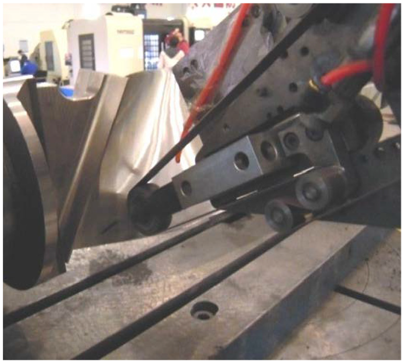
Abrasive belt polishing experiment of blade.
As shown in Figure 31(a), Infinite Focus G4 automatic zoom 3D surface measuring instrument for blade surface roughness measurement, 36 which can perfectly combine the topography measurement and roughness measurement in the same system, with the highest vertical resolution of 10 nm. During the roughness measurement, randomly measure five points on the blade surface and calculate the average value as the final measurement result. Micro analysis of blade surface is shown in Figure 30.
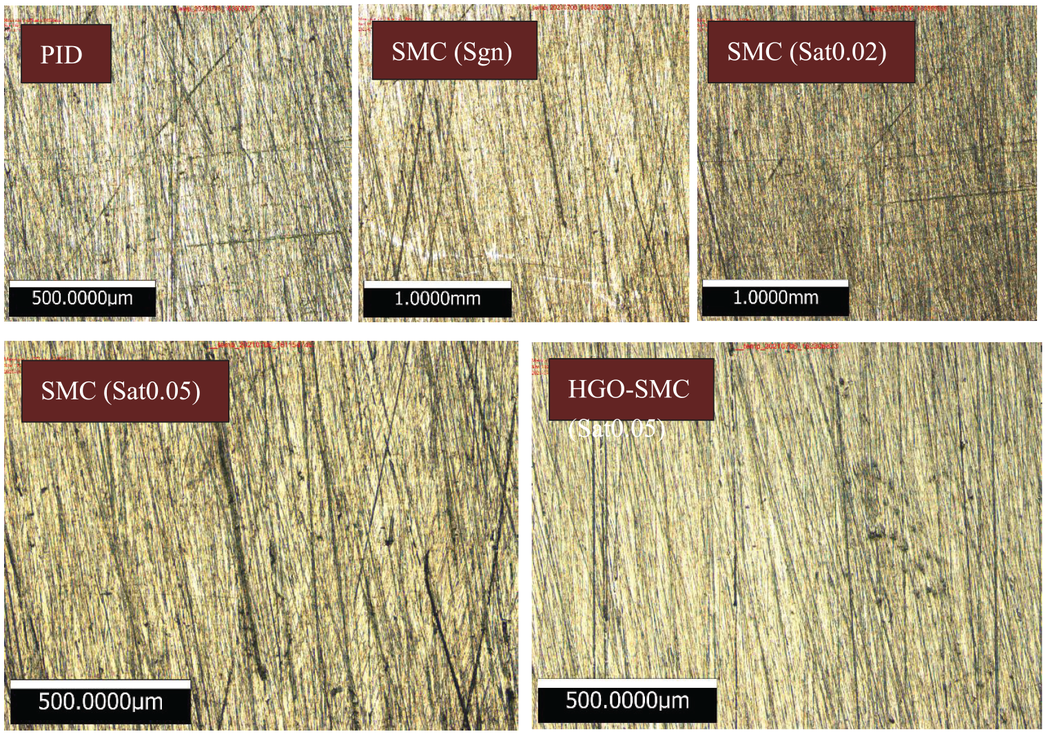
Micro analysis of blade surface.
The 3D coordinate measuring machine is used to measure form and position accuracy error of the blade as shown in Figure 31(b). Divide the polished blade into five sections and measure the error of the blade profile, and the test results are obtained after scanning and data processing, as shown in Figure 32.37,38 Three measuring points are sampled at different sections of the blade basin and back, and the normal error of the measuring points is used to represent the form and position accuracy error of the polished blade.

Blade surface quality inspection equipment: (a) 3D surface measuring instrument and (b) 3D coordinate measuring machine.

Schematic diagram of blade shape and position accuracy inspection.
The surface roughness and form and position accuracy errors of polishing experiments are shown in Figure 33. The experimental results show that the HGO-SMC algorithm can effectively reduce the surface roughness and improve the form and position accuracy, which can also ensure that the polishing force control system can control the polishing force in real time, stably and accurately.

Comparison of properties of blade polishing.
Conclusion
In this paper, force analysis of polishing structure, abrasive belt-wheel and contact surface is carried out, and the prediction model of polishing force applied is established.
Analyzing the prediction model of polishing force, it can be know that the polishing force should be time-varying. Therefore, higher requirements are put forward for the control precision, robustness, and sensitivity of the polishing force controller. When the derivative of polishing force cannot be measured, a sliding mode control algorithm based on high gain observer is proposed to achieve stable control of polishing force. The high gain observer can feedback the estimated value of the first derivative to the sliding mode controller.
The simulation and experimental results show that the HGO-SMC control algorithm has stronger robustness, higher control accuracy, smaller steady-state error, and stronger interference suppression compared with PID, SMC with sgn, SMC with sat(0.02), and SMC with sat(0.05). HGO-SMC can also effectively ensure the polishing quality of the blade surface, reduce the surface roughness, and improve the form and position accuracy.
Footnotes
Handling Editor: Sharmili Pandian
Declaration of conflicting interests
The author(s) declared no potential conflicts of interest with respect to the research, authorship, and/or publication of this article.
Funding
The author(s) disclosed receipt of the following financial support for the research, authorship, and/or publication of this article: This study was supported by the National Natural Science Foundation of China (Grant No.52105483); the Major Special Projects of Aero-engine and Gas Turbine (2017-VII-0002-0095).