
Abstract
This study addresses the critical need for enhanced vibration control and standardization in electric motors, pivotal to the operational efficiency of electric vehicles and thus, environmental sustainability. Recognizing the gap in unified standards for managing machine vibration, we propose a novel, integrated framework combining advanced vibrodiagnostic techniques and rigorous standardization processes. Our methodology involves a detailed analysis of existing vibration control practices, identifying deficiencies in current standards, and presenting an improved, comprehensive guideline tailored to electric motors’ unique requirements in transportation applications. The innovation of our approach lies in its dual focus on technical precision and environmental sustainability, offering a significant leap forward in vibrodiagnostics. We demonstrate the framework’s practical value through its potential to revolutionize electric motor maintenance strategies, enhance machine longevity, and reduce environmental impact. This research contributes to the broader goals of reducing greenhouse gas emissions and advancing sustainable transportation, emphasizing the importance of vibration control standards in achieving energy efficiency and reliability in electric transport systems.
Keywords
Introduction
In the pursuit of environmental sustainability within the transportation sector, integrating energy-efficient technologies is crucial for minimizing energy consumption and environmental impact. This requires modernizing infrastructure, notably through enhancing traditional vehicles and adopting electric vehicles (EVs), supported by robust development. Such technological advancements are pivotal in operational efficiency improvements, which are central to our study’s focus on rigorous vibration control and standardization in electric motors.
Public transport modernization, such as in Tanjungpinang, 1 reduces reliance on personal vehicles, while integrating solar energy into EV management systems 2 promotes sustainable efficiency. Innovations like active four-quadrant converters 3 and supercapacitors 4 improve EV reliability. Optimizing lithium-ion batteries 5 and exploring soil mechanics for infrastructure 6 support sustainable transport.
Research on locomotive diesels’ rotation frequency 7 and developing energy-efficient urban transport 8 show potential for significant improvements in transport systems. Green energy innovations 9 contribute to eco-friendly infrastructure.
However, to fully realize the potential of sustainable transportation, it is equally important to integrate Intelligent Transportation Systems (ITS). ITS extends beyond traditional approaches by incorporating advanced technologies that enhance traffic management and vehicle operation, thereby contributing significantly to sustainability.
Recent studies by Rongge et al. 10 and Zhou et al. 11 have explored the role of ITS in reducing urban traffic congestion and designing energy-efficient lighting systems for road traffic, respectively. These studies highlight the critical role of ITS in enhancing the sustainability of transportation systems through AI-enabled technologies and intelligent infrastructure design.
There is a worldwide move towards energy efficiency. This has led to research in technologies related to electric transport. 12 Studies focus on energy-efficient public transport, managing energy in electric vehicles, 13 and strategies for decarbonization. 14
Amidst these technological advancements and research efforts, the educational sector, which plays a crucial role in nurturing the next generation of engineers and technologists, has faced unprecedented challenges due to the pandemic. 15 These challenges underscore the importance of resilient and adaptive educational frameworks in sustaining the momentum toward sustainable transportation solutions.
Reliability, durability, and controllability of electrical equipment is crucial.16–19
The authors of Matusevych et al. 16 developed a method for determining the residual technical life and expected life of a power transformer for railway traction substations. This method allows you to fully use the technical resource of the transformer, reduce economic costs and labor costs.
The authors Ostroverkhov and Buryk 17 developed a speed control system for synchronous motors with field weakening, which provides voltage and stator current limitation in transient processes, as well as low sensitivity to parameter changes and simplicity in control system implementation.
The authors of paper 19 claim that traction electric motor failures account for 20% of all electrical equipment failures. Therefore it is very important to choose the most accurate and effective diagnostic method.
Diagnostic techniques vary from acoustic signal analysis 20 to thermal imaging 21 and analyses of permanent magnet motors. 22
Spectral analysis is used for diagnosing electric vehicle propulsion systems, 23 while selecting parameters for hybrid vehicle traction. 24
Article 24 presents a simulation model of an electric drive system for diagnosing an electric vehicle using the method of spectral analysis of the electrical process of power supply to propulsion systems. According to the authors, in the future this model can be used for virtual studies of the dynamic modes of an electric drive and studies related to the identification of structural and parametric faults that occur in its circuits.
It is important to note that vibration diagnostics occupies a special place in diagnostics – a non-destructive testing method based on the analysis of a set of vibration parameters to determine the condition of equipment. This is due to the fact that it allows you to diagnose most defects and malfunctions of machines.
Vibrodiagnostics detects motor defects, reducing repair times and costs. 25 It’s crucial in the transport sector for maintaining operation and safety.26,27 Advanced control strategies enhance electric motor performance. 28
This work introduces a framework for machine vibration standardization and control, tailored to electric motors in transport. By integrating vibrodiagnostic techniques with sustainability goals, it aims to improve electric transport systems’ energy efficiency and environmental impact. This approach, leveraging advanced data analytics, promises to revolutionize electric motor maintenance.
Recent advancements in vibration control and diagnostics, such as neural network-based mitigation, 29 vibration control for robot manipulators 30 and, 31 and energy-efficient vibration-driven robots, 32 add to this field.
This effort supports sustainable development, aiming for a more sustainable and energy-efficient future. It underscores the importance of environmental sustainability in vibrodiagnostics, contributing to the global transition toward sustainable transportation solutions.
Instruments and equipment
For measuring vibration levels, instruments were used that provided accurate and reliable data collection on vibration. The vibration levels of electric motors were quantitatively determined in decibels (dB), focusing on the maximum root mean square (RMS) values of vibratory acceleration. Measurements were conducted on specialized test benches equipped with vibro-acoustic decoupling. Calibrated instruments were used for vibration measurement, specifically: equipment from Brüel & Kjær (Denmark), a leader in acoustic and vibration measurement technologies; vibration analyzers (Models 2120, 2133, and 2130); a vibration sensor (Model 4376); a charge amplifier (Model 2635), and others.
Regulation stages for machine vibration
Reducing vibration in machines directly contributes to their efficiency. The reduction of vibration levels is associated with decreased mechanical stress and wear, leading to a longer operational lifespan of the machinery. Moreover, lower vibration improves the precision and stability of machine operations, which are crucial for maintaining optimal performance and ensuring energy efficiency. By minimizing unnecessary movements and fluctuations, machines can operate closer to their designed parameters, which reduces energy consumption and enhances overall system efficiency.
In machine design, the primary criterion for vibration normalization is ensuring the availability of adequate resources and reliability. In production, the focus is on quality control during manufacturing, while during machine operation, the priority is monitoring the technical condition of the machine.
The normalization of machine vibrations involves several stages.
The first stage is to determine the frequency range that requires vibration control.
Traditionally, mechanical engineering has employed a method of monitoring and normalizing vibrations based on the maximum displacement amplitude at a particular frequency of the oscillatory process. This approach is still widely used, as evidenced by current industry standards and norms. Monitoring low-frequency vibrations in machines provides information about vibration power, which is proportional to the square of the displacement amplitude. Additionally, low-frequency vibrations resulting from variable loads in machine components serve as an indirect indicator of their technical condition.
However, this method has a drawback in that it does not provide information on the harmonic components of the vibration process. This information is necessary for a more comprehensive evaluation of the machines’ technical condition, as well as for assessing vibrations in accordance with sanitary and hygienic requirements.
Empirical evidence suggests that reliable monitoring of machine technical conditions requires vibration control within the frequency range up to 10 kHz.
Sanitary and hygienic requirements also impose limitations on vibrations throughout the frequency spectrum, ranging from particle oscillations in the Hertzian range up to 200–300 Hz. Airborne noise generated by vibrations can harm the human body, and regulations to limit airborne noise usually cover a frequency range up to 10 kHz. Therefore, it is necessary to control vibrations in the infrasonic and audible frequency ranges to ensure a complete and comprehensive assessment of machine vibration activity. In summary, it is advisable to control and normalize the vibration parameters of machines from the minimum frequency of the oscillatory process up to 8–10 kHz.
In recent years, numerous machine-building enterprises both domestically and abroad have implemented acceptance control procedures for machines based on the spectral composition of vibration. The automotive, diesel, turbine, and electric machine building industries have all adopted this approach.33,34
The second stage of controlling and normalizing vibration parameters is the selection of the optimal frequency analysis bandwidth.
Although harmonic analysis provides the most comprehensive characterization of the vibration process, it is not practical for standardization purposes due to fluctuations in vibration parameters. Therefore, frequency-band vibration analysis is necessary for normalization, as it helps to reduce testing time in mass production settings. To compare the vibration levels of mass-produced machines against set requirements, it is typical to limit the control and normalization of vibration parameters to the octave frequency band.
It is important to learn more about the technical condition of machines during operation. Gathering preliminary data on possible defects is also crucial. Using one-third or half-octave frequency bands is recommended for controlling and normalizing vibrations. If it is necessary to analyze the vibration spectrum in detail, which falls under the category of study rather than control, narrow-band vibration analysis is utilized. 13
For hygiene assessments of vibration, the Technical Committees ISO/TC 108 recommends octave measurement bands, 35 and most departmental regulations align with these recommendations.
The third stage of monitoring and normalizing machine vibration involves selecting parameters for the intensity of the vibration process.
Kinematic parameters used include displacement, speed, and acceleration. Another parameter is called vibration power. However, measuring vibration power is practically difficult. Vibration power is not widely used for normalization yet.
Currently, low-frequency vibration control and standardization adhere to technical and medical requirements using vibration displacement amplitudes. This is typically measured using electronic equipment or simple mechanical meters like vibrometers and vibrographs.
Transitioning to spectrum-based vibration control makes displacement evaluation challenging. Mechanical vibration meters are unsuitable for this type of measurement. Electronic equipment used instead is equipped with sensors that detect acceleration and speed. Converting these parameters into displacement requires integration, which necessitates more complex equipment and may introduce additional errors. Additionally, measuring high-frequency components of vibrational displacements near the lower limit of the instruments’ resolution may impact measurement accuracy.
It is important to note that vibroacceleration is a kinematic parameter equivalent to the acceleration of displacement (the second derivative of vibrodisplacement) of a point oscillating at a certain frequency. Vibroacceleration carries information about the parameters of vibrodisplacement and vibrospeed. Therefore, by measuring vibroacceleration parameters, complete information about the technical condition of the machine can be obtained.
Using vibration acceleration as a parameter has many advantages. It can indicate dynamic load under certain conditions. Piezoelectric vibration sensors, which are small and sensitive, respond directly to acceleration. However, the spectral distribution of vibration acceleration does not always align with that of vibrational power, as acceleration increases with frequency.
Vibration speed has been the primary parameter used to determine vibrational power. This parameter is directly linked to the physiological state of individuals, as evidenced by its use in some medical requirements and standards. As a result, vibration speed is a convenient parameter for controlling and normalizing vibration during the assessment of machine technical condition, both during production and operation. Sanitary and hygienic standards have accepted vibration speed as the primary parameter for assessing the safety of vibration exposure.
The fourth stage involves selecting the appropriate parameters for monitoring and normalizing vibration, which includes determining which vibration value, should serve as the basis for assessment: maximum amplitude, arithmetic mean, or root mean square (RMS) (effective). When dealing with harmonic or near-harmonic oscillations, the amplitude value provides the simplest expression of the magnitude of these oscillations and is of practical interest from the perspective of machine mechanical strength and physiological impact on individuals. Therefore, most requirements for limiting low-frequency vibration are based on amplitude values.
Assessing vibration at a particular frequency does not pose any difficulties. However, when monitoring and normalizing vibration in frequency bands, the amplitude value characterizes only the highest level within a given frequency range, without reference to a specific frequency. Furthermore, external noise that is superimposed on a stationary random process enters and distorts the vibration measurement when using the amplitude value.
The use of the arithmetic mean as a measure of vibration is not convenient because the instrument readings, as with measuring amplitudes, are dependent on the phase shift of the components. Due to the incomparability of the measured values, this method of vibration assessment is especially unsuitable for standardization.
These issues can be resolved by using the RMS value as the measure of vibration. The RMS value of a variable parameter is determined by the formula:
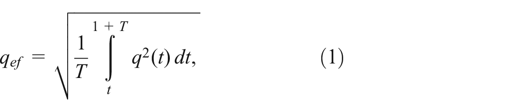
where T is the period, sec.
The effective value of a variable parameter represents the value of a time constant parameter equivalent in energy to the variable parameter. Therefore, the effective value provides a single equivalent value for both purely harmonic and complex oscillatory processes, enabling their comparison.
By utilizing the RMS value for vibration assessment, the need to determine the phase angle between individual components is eliminated. This highlights the efficiency of using the RMS value for monitoring and normalizing vibration.
The fifth stage of vibration parameter control and regulation is critically important and involves choosing the optimal location and direction for vibration measurements. Such measurements are typically conducted to ensure proper diagnostics and monitoring of equipment condition. Vibrations occur in different elements of a machine. These vibrations affect various parts of the machine in different ways. This variation can be due to several factors. Factors include the superposition of vibrations from different sources, resonance phenomena in the structure, and effective damping and vibration isolation.
For example, Figure 1 displays the spectrograms of vibration levels of an electric motor, taken at different points on the support surface above the dampers. The results indicate significant variations in vibration levels, which manifest across a wide frequency range. This underscores the necessity of precisely choosing the measurement location for an adequate assessment of the machine’s vibrational state.
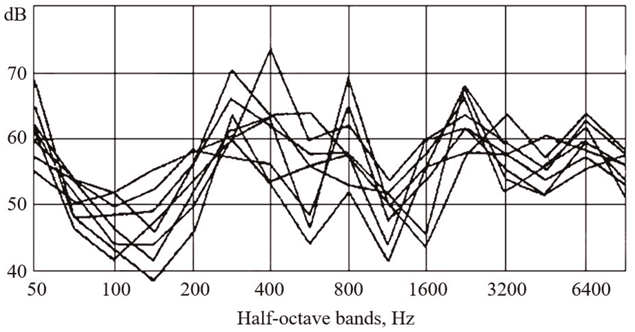
Vibration levels of the electric motor at different points of the supporting surface above the shock absorbers.
Even greater differences in vibration levels can be observed when analyzing data collected from different nodes of the same machine, as shown in Figure 2. Specifically, the spectral components of vibrations of an electric pump, measured on the bearing cover, on the casing, and on the support legs, demonstrate significant differences. Comparing spectrograms obtained from different locations of the same equipment under the same operating conditions indicates substantial differences that must be considered when defining norms and control parameters.

Vibration levels at different points of a multistage pump with a horizontal rotor.
Comparison of spectrograms taken at different points on the same machine with the same operating mode indicates significant differences.
The direction of vibration measurement at a selected point, whether it be vertical, horizontal, or axial, is equally significant. Numerous data suggest a substantial difference between the levels of vibration measured at the same location but in different directions. Hence, there is a requirement for precise regulation of locations and directions for measuring vibration during its normalization and control.
Most regulatory documents that limit the vibration of machines, from the perspective of mechanical strength, stipulate control on bearing caps in three perpendicular directions.
Regarding problems associated with the propagation of vibration, information about the vibration emitted by the machine at the base of the structure (foundations, floors, supports, etc.) is of primary importance. In such cases, vibration control and standardization are conducted in the support units of the machines (feet, flanges, etc.). The vibration sensor is placed on the support unit of the machine near the screws that fasten the machine to the foundation or directly on the screw head. Control and normalization of vibration, in this scenario, can be carried out either according to measurements at one point where its level has a maximum value or based on the average value of measurements at several characteristic points.
In the context of controlling machine vibration during operation to maintain technical condition, normalization of vibration parameters can be applied to any of its nodes. It is recommended to select a location where the components that best represent the main operations of the machine can be heard most distinctly.
The sixth stage involves selecting the operational mode in which vibration control will be implemented. As vibration levels are highly dependent on working process parameters, the vibration control mode must be clearly defined. Typically, the main operational mode of the machine is used as the normalized mode.
For mechanisms with multiple modes, vibration control can be implemented in various characteristic modes such as under load, at idle, at full or reduced speed, etc. Each mode may have its own criteria for limiting vibration. The relationship between changes in vibration levels of power machines and their power and number of revolutions expressed by the formula:

where 1 and 2 are indices denoting the compared values of power N and number of revolutions n.
Table 1 presents the experimental values of λ and k for the primary types of power machines. Comparable relationships exist for other machine types and mechanisms, underscoring the necessity of specifying their operational modes in regulatory documentation.
Approximate values of the coefficients λ and k for the main types of power machines.

Test conditions play a crucial role in vibration control. Special attention must be given to the level of vibration interference that affects the vibration of the object under control.
The total vibration level L* resulting from the useful signal L1 and interference L2 can be expressed using the following formula, (dB):

The most significant portion of this relationship is illustrated in Figure 3. It can be inferred from the figure that to rectify an error exceeding 0.5 dB, the difference ΔL between the vibration levels of the useful signal and interference must be at least 8–10 dB.

Graph for determining the total vibration level of two sources.
Shock absorbers are employed to decrease interference intensity from external sources in vibration control machines. The usage of shock absorbers is also necessitated by the requirement for an inertia-rigid decoupling of the machine from the foundation. When the machine is rigidly fastened to the foundation, its vibration characteristics are significantly dependent on the foundation’s mass and rigidity. In mechanical engineering practice, cases have been documented where a machine functioning normally on one foundation was pushed into an emergency state after being relocated to another foundation. This rise in vibration was mainly due to resonance in the machine-foundation system. As the genuine vibration characteristics of this system can only be obtained through testing in real operating conditions or conditions that closely mimic them, state standards for limiting the vibration levels of turbo and hydro generators entail the monitoring of the vibration characteristics of these machines under normal operating conditions.
This approach may be deemed reasonable for individual machines in individual production scenarios. However, it is unsuitable for multi-batch production, where machine vibration characteristics must be assessed on acceptance factory stands. As most requirements and standards for limiting vibration apply simultaneously to various machines, including identical machines installed on different foundations, test conditions must be established that allow for the objective determination of vibration characteristics. To achieve this, a frequency separation of forced and natural vibrations should be achieved during machine installation on shock absorbers that does not significantly introduce resonance testing into amplitude characteristics. Current regulations typically specify requirements for frequency differentiation, which state that the frequency of free vibrations f c of a machine installed on shock absorbers should be 2–4 times lower than the frequency of the disruptive force f of the primary working process of the machine (measured in revolutions per second).
The recommended frequency delimitation area for the bench system “machine-shock absorbers-foundation” is shown in the resonance diagram (Figure 4) through hatching. It may be challenging for low-speed mechanisms to reach the upper limit. Additionally, pliable shock absorbers in aggregate assembly may contribute to machine misalignment when operating under load, thereby increasing vibration. Therefore, for mechanisms and machines with no disruptive forces at half the frequency of the primary working process, it is acceptable to install them on the stand on shock absorbers that provide the lower limit of the separation factor specified in the diagram.
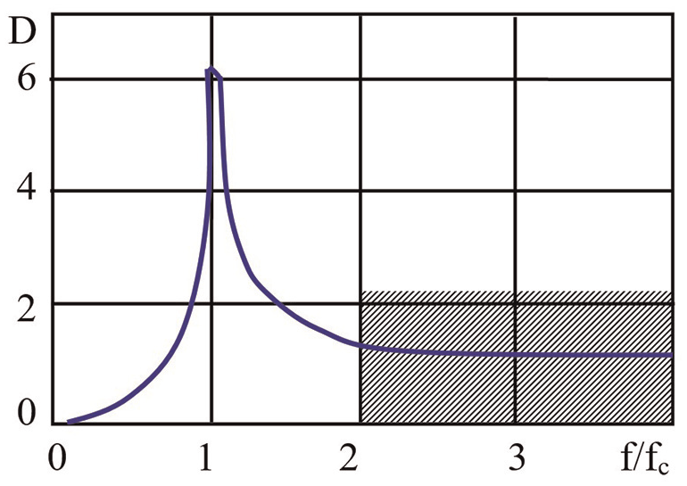
Recommended area of frequency delimitation of the “machine-shock absorbers-foundation” system (shaded bar).
It is worth noting that some methods suggest conducting vibration control of machines when they are firmly mounted on an intermediate platform, which in turn is mounted on shock absorbers. This is done in an attempt to bring machine operation closer to natural conditions and improve the detection of resonance phenomena by adding additional mass and increasing rigidity. However, it should be kept in mind that the use of shock absorbers for machine installation is becoming increasingly common in actual operational conditions. Therefore, vibration tests of machines on shock absorbers are more representative of real-world scenarios. In any case, to avoid possible discrepancies in establishing requirements or norms for limiting machine vibration, it is important to indicate the method of attaching the machine to the foundation as a prerequisite.
Results and discussion
Experience has demonstrated that in order to effectively regulate the vibration of machines’ technical condition, it is essential to regulate the vibration across a broad frequency range, extending from the minimum to 8–10 kHz. If a precise spectrum interpretation is needed, narrow-band vibration analysis should be employed.
Kinematic parameters, including displacement, velocity, and acceleration, or a compound parameter, vibration power, can be utilized to assess the intensity of vibration processes. Vibration displacement amplitudes are suitable for regulating low-frequency vibrations, while vibration acceleration is preferable for managing the spectrum.
Vibration velocity is the primary parameter for measuring vibration power. It is utilized in medical requirements and standards as a factor that affects human physiological states. Furthermore, it is the primary parameter for sanitary and hygienic standards and is used in vibroacoustic diagnostics and a comprehensive evaluation of the technical state of machinery and mechanisms.
Amplitude values are a straightforward way to quantify harmonic or similar vibrations that are relevant to the mechanical strength of machines and the physiological impacts on individuals. Amplitude values are the basis for most limitations on low-frequency vibrations, but RMS values can be used to regulate and restrict vibrations. When monitoring and normalizing vibration parameters, it is critical to select the location and direction of measurements, which are typically bearing caps in three perpendicular directions. Information about the machine’s vibration at the heart of the design is essential for understanding the propagation of vibration, and control and regulation are carried out at the machine’s supporting nodes. Vibration control should be performed during the machine’s main specific mode of operation. In multi-mode mechanisms, vibration control can be conducted in several characteristic modes.
Vibration control is critical, necessitating attention to the testing conditions, particularly the level of vibration interference that may be imposed on the controlled object. To achieve more accurate results, the difference between the useful signal and interference’s vibration levels should be at least 8–10 dB, in order to avoid an error that may exceed 0.5 dB.
To reduce interference intensity from other sources, machines undergoing vibration control can be mounted on shock absorbers. However, it is critical to ensure a frequency separation between forced and natural oscillations to avoid significant resonant distortions in the amplitude characteristic. To accomplish this, the frequency of free vibrations of the machine on shock absorbers should be 2–4 times lower than the frequency of the main working process’s disturbing force.
Some methods suggest mounting machines rigidly on an intermediate platform with shock absorbers for vibration control. However, using shock absorbers directly in field conditions is becoming more common. Consequently, vibration tests of machines on shock absorbers correspond more closely to reality. Regardless of how the machine is affixed to the foundation, it is essential to specify this method in the requirements (norms) for limiting vibration to avoid possible contradictions.
Conclusion
The use of energy-efficient technologies not only reduces energy supply costs but also minimizes negative impacts on the environment. Modernizing vehicles and utilizing electric vehicles with appropriate infrastructure is a key aspect of energy efficiency. Electric transport is an essential area of development as it is more environmentally friendly and helps reduce air pollution. The electric motor, one of the main components of electric transport, has specific requirements for maintenance and repair, including reliability and controllability. Vibration diagnostics is an effective and informative method for diagnosing electric motors, reducing their repair time and costs, and ensuring electric machines’ safety and reliability.
Developing requirements for regulating and controlling machine vibration is critical to ensure a safe working environment, machines’ reliability, and energy efficiency. This article examines the main issues associated with requirements for regulating and controlling machine vibration, describes the six main stages of vibration regulation, methods for measuring vibration and determining its characteristics, and acceptance criteria. The study also considers the influence of vibration on human health and machines’ technical condition, as well as requirements for designing machines to account for vibration. This research will be valuable to experts in regulating and controlling machine vibration and researchers working in this field.
Footnotes
Handling Editor: Aarthy Esakkiappan
Declaration of conflicting interests
The author(s) declared no potential conflicts of interest with respect to the research, authorship, and/or publication of this article.
Funding
The author(s) received no financial support for the research, authorship, and/or publication of this article.
Ethical considerations
As we advance the application of our framework for enhancing the performance of electric motors through rigorous vibration control, it is crucial to consider the ethical implications of these technological advancements. The pursuit of environmental sustainability and operational efficiency must be balanced with a commitment to ethical practices in engineering and technology development.