
Abstract
In the realm of mechatronics, robots stand out as emblematic manifestations of societal progress. The synergy between the evolution of robotic technologies and artificial intelligence (AI) has been pivotal in refining performance and elevating the automation capabilities of robotic arms. This study delves into the integration of the long short-term memory (LSTM) AI model in the control of the inverse dynamics of a six-degree-of-freedom welding robot arm, employing a velocity-based motion control methodology. Noteworthy for its innovative operational approach, this method is widely employed across diverse models of industrial robotic arms. The research findings underscore the superior optimization results achieved by the LSTM model during the accumulation of control signals, surpassing previous studies in the same domain. Anticipated as a catalyst for substantial improvements in the efficiency of welding robot operations, this model heralds a promising avenue for future advancements in optimization techniques.
Keywords
Introduction
Robots are a prominent product of the field of mechatronics, reflecting the societal development in recent years. Robots have made significant strides over the centuries. The first robots were introduced into the industrial sector in the 1960s to replace humans in performing strenuous and hazardous tasks in hazardous environments.1,2 Due to the increasing demand for higher production output and the execution of complex tasks, industrial robots need to possess more flexible and intelligent adaptability. Today, in addition to their initial rudimentary applications in manufacturing, robots are also employed in various other fields such as healthcare, medical care, agriculture, shipbuilding, construction, and national security. Several robot groups have garnered research and production interest recently, as depicted in Figure 1:

Classification of several robot groups and the research direction of this draft.
According to Figure 1, robots are classified into four groups,3,4 including Robot Manipulators, Mobile Robots, Bio-Inspired Robots, and Personal Robots. Among these, Robot Manipulators encompass Industrial Robots, Medical Robots, and Rehabilitation Robots.5–7 Mobile Robots have been extensively researched,8–10 such as Autonomous Guided Vehicles (AGVs), Autonomous Underwater Vehicles (AUVs), Unmanned Aerial Vehicles (UAVs), and Space Robots. With Bio-Inspired Robots, recent studies have focused on two primary types,11–13 namely Walking Robots and Humanoid Robots. Additionally, research groups have developed various underwater Bio-Inspired Robots like Robotic Birds, 14 Spider Robots,15,16 Robotic Dogs,17,18 along with biomimetic structures mimicking marine life movements. Currently, civilian Robot applications are commonly found in Home Robots and Personal Robots.19,20 Despite the structural differences among these Robot types, contemporary research is oriented toward service applications and the operations of Robots in natural environments. With the advancement of society and modernization in developed countries, numerous new services have emerged, altering the perception of Robots from serving industrial purposes to meeting the social and personal needs of individuals. Robots are designed to serve humans as effective and versatile aids.
In material processing industries, robots function as machining tools. Consequently, the robot arm is equipped with an apparatus in place of a gripper mechanism.21,22 The applications of robots in material processing industries include the following technologies: spot welding, continuous arc welding, painting, metal processing, etc. Among these, spot welding is a common application of industrial robots, particularly in the automotive assembly industry. Spot welding can be performed through two methods23–25: using a spot welding machine and using a spot welding gun. The spot welding machine consists of two electrodes that firmly clamp two parts and pass a high-value current, resulting in the two parts being welded together at one point. 26 In automobile assembly lines, dozens of spot welding robots work together according to a pre-set program. Spot welding robots must be of considerable size, capable of carrying a load to precisely control the heavy welding gun. The robot needs to position the welding gun accurately and in the right direction, especially in hard-to-reach positions for humans. Therefore, the number of degrees of freedom of the robot must be large, and the computer memory must have a high capacity. The benefits of automating the spot welding technology using robots include enhancing product quality, ensuring safer operations, and better control over the welding process. Similarly, continuous arc welding is used in the welding technology for joining two metal components or welding pipes, rims, etc. The working environment for arc welders is hazardous and toxic: high temperatures, ultraviolet rays generated during the welding process pose a danger to human vision. However, due to certain technical challenges, such as improving the welding quality when there are changes in the composition of the welding material, and economic issues, robots are only used in the continuous arc welding technology in production lines with moderate to high output. Moreover, surface coating using robots is becoming popular in the industry as a substitute for human labor to improve working conditions. Controlling the paint spray gun is crucial to meet product quality requirements. The controlled parameters include paint spray flow and pressure. In the production line, a painting robot is a part of the system, typically working with a conveyor system carrying the parts to be painted. Hence, the synchronization between the painting robot and other processes in the production line is also emphasized in the design of the painting line automation.
Artificial Intelligence (AI) is profoundly influencing various fields, including the operation of robotic arms.27,28 We can observe specific applications of artificial intelligence in the operation of robotic arms, including the following issues: (1) AI can be utilized to program robotic arms to perform specific tasks in the production process.29,30 This enhances efficiency, minimizes errors, and increases precision in industrial manufacturing; (2) Machine learning technology enables robotic arms to accurately identify and classify objects, thereby assisting them in tasks such as assembly, sorting, and packaging more efficiently31–33, (3) AI can optimize the transportation and distribution process by employing robotic arms to automate tasks such as packaging, stacking, and distribution of goods.32,34,35 This reduces costs and speeds up the transportation process; (4) AI can be integrated into robotic arms to create a better interaction experience with humans.36–38 This can help robotic arms work alongside humans in a manufacturing environment and perform complex tasks more easily; (5) AI can be used to predict potential issues and conduct regular maintenance on robotic arms.39,40 This helps optimize operations and extend the lifespan of robotic arms. In summary, artificial intelligence plays a crucial role in optimizing the performance and enhancing the automation capabilities of robotic arms through control methods, while creating a safe and efficient working environment in manufacturing and service industries. Typically, there are numerous control methods for robotic arms, as depicted in Figure 3. Regarding the working characteristics of the robot, the control problem can be divided into two types: coarse control and fine control. In the coarse control problem, the appropriate control law is determined to ensure that the speed and position of the joint movements adhere closely to the designed trajectory for the minimal transition time. The second problem pertains to the process when the robot moves and interacts with the working environment, such as the case of the robot assembling a component into a machine device. Therefore, this working process will require both force and position control. Coarse motion control or trajectory control can be performed in joint coordinates or task coordinates depending on the trajectory designed for joint coordinates or task Decac coordinates. Fine motion control is force control, essentially combining force and trajectory control. Force control consists of impedance control and hybrid control.
Addressing the limitations of previous research, this paper integrates the long short-term memory (LSTM) artificial intelligence model into the control of the inverse dynamics of a six-degree-of-freedom welding robot arm using a velocity-based motion control approach as shown in Figure 2. This innovative operational method is commonly employed in various models of industrial robotic arms. The results of this study demonstrate that, during the accumulation of control signals, the long short-term memory (LSTM) model yields significantly superior optimization results compared to previous studies of the same kind. In the future, this model is expected to substantially enhance the optimization efficiency of the welding robot’s operations.

The integrated model in this research.

The robot control model from this research.
The research integrates LSTM AI into controlling a six-DOF welding robot arm, improving efficiency and accuracy. It constructs a reverse control model for point and trajectory welding, addressing complexity and practical challenges. By integrating LSTM, it accumulates past points for current and predicts future ones, outperforming previous models. This approach shows promise for enhancing economic efficiency and accuracy in industrial robot operations.
Motion control model of the multi-degree-of-freedom welding robot
With the aim of designing a welding robot arm for the purpose of welding components in automated assembly lines, the robot utilizes the angular coordinate system as the control model for the robot arm, a coordinate system that has been widely used in recent research. In this system, the three basic movements are executed through rotations, meaning the basic movements are determined by six rotations in the original coordinate system. All arm components are located on a vertical plane, making the basic calculations planar problems. As this plane rotates, facilitated by the welding clamp model, it can weld components at any position within the working area. A notable advantage of robots operating in the angular coordinate system is their compactness; the operations are relatively compact in relation to the size of the large robot. Through practical surveys, to enhance the flexibility of the arm used in the industry, the arms must have a high number of degrees of freedom. However, this number of degrees of freedom should not exceed six, as shown in Figure 4. The main reason is that with six degrees of freedom, if arranged properly, it is sufficient to create the necessary flexibility of the final operating step to access the object (within its workspace) from all directions. Additionally, having more than six degrees of freedom would be less economical and more challenging to control.

The welding robot model surveyed in the research.
The study will establish a table of DH parameters through Table 1
Denavit–Hartenberg table of kinematic parameters of the robot.

Establishing the motion rule of inverse kinematics
In terms of the end-effector’s position and orientation, the joint variables are determined by inverse kinematics. Mathematically, inverse kinematics involves the search for the elements of the vector q

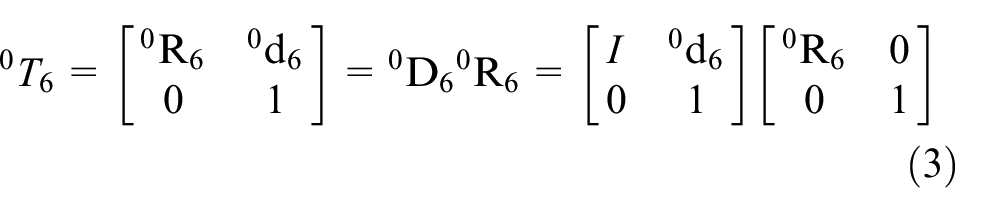
When a transformation

Computing-controlled robots are typically driven in joint space, however, operational objects are often represented in the global Cartesian coordinate system. Therefore, the transfer of kinematic information between the joint space and the Cartesian space is a necessity for the robot. To control the configuration of the end-effector to reach an object, the inverse kinematics problem needs to be addressed. Hence, we need to determine the required values of the joint variables to achieve the desired position and orientation. The inverse kinematics problem can be decomposed into two sub-problems, namely inverse position kinematics and inverse orientation kinematics. The practical outcome of the decomposition is the partitioning of the problem into two independent sub-problems, each with three variables. According to the separation principle, the overall transformation matrix of the robot can be decomposed into a translation and a rotation.
Most wrist-jointed robots are composed of three revolute joints with axes intersecting and orthogonal at the wrist points. We can separate the wrist and arm kinematics by decomposing the overall forward kinematics transformation matrix

Whereby, the wrist orientation matrix is:

And the position of the wrist is:

The wrist position vector
In the case where the arm includes the coordinate frame of the tool in forward kinematics, the separation must be carried out in a particular equation to eliminate the influence of the tool on the robot’s kinematics.

Computing the inverse kinematics using the separation method
Calculating three rotation angles θ1, θ2, θ3

With the parameters y, p, r representing three rotations around the x, y, z axes, where x, y, z are the coordinates of the end-effector point, we have
The point P is considered as a point where it attaches to a spherical wrist. Therefore,

Geometric diagram representing joint θ1.
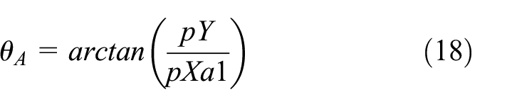
The first angle

Inferred:

with

Inferred:

To find both
The first case: the wrist point is located in front,

Geometric diagram representing joints θ2 and θ3 in case 1.
The second case: the wrist point is in the middle,

Geometric diagram representing joints θ2 and θ3 in case 2.
Here, we do not consider the case where the wrist point is located behind, which will lead to complexity in the process of programing and calculating the control of the robot and misconfiguration of the robot due to the limitations of the initial rotation angles, in this case, the Denso VS_6556EM robot arm
Calculate case 1:


From the angles calculated above, deduce

Calculate case 2:


From the angles calculated above, deduce

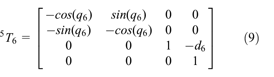
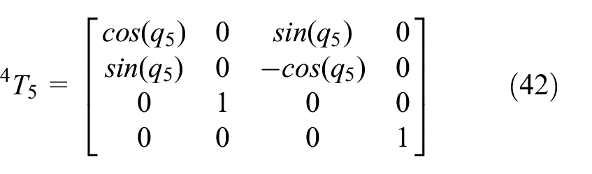
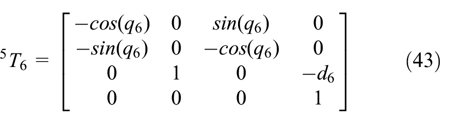
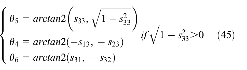
Calculating three rotation angles θ4, θ5, θ6
Finding


As a result, we can derive that:


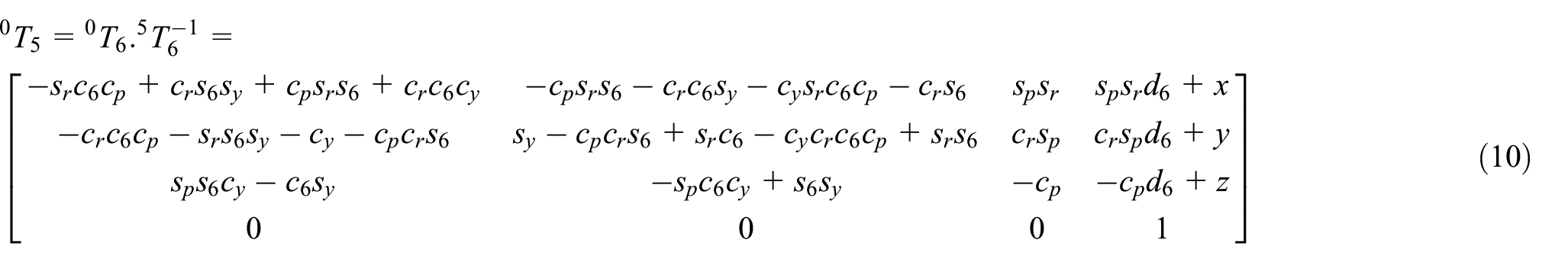
From

Furthermore, we obtain

with

As a result, we can derive that:

Solving the two matrices above, we find

Long short-term memory
To predict the future welding point value, the necessary data of the robotic arm will not only include the current data being processed but also the values achieved in the past. In other words, the model in this study needs to “remember” the past data values in order to make predictions for the future. The recurrent neural network (RNN) model41,42 has the advantage of “remembering” past values and using them to predict the future. However, the RNN model encounters difficulties in “remembering” values over long periods, leading to the model no longer retaining crucial values beyond that time. To address this issue, a model introduced by Hochreiter and Schmidhuber 43 and further developed by Graves 44 in 2013, called Long Short Term Memory (LSTM), was introduced. The LSTM model employs three special gates to enhance “memory” and manage data, including the input gate, forget gate, and output gate. The input gate is used to calculate the weight for the input value, where a higher weight implies a more significant influence of the input value in the future. The forget gate decides which input values to retain and which to forget. The output gate generates the result of the computation process within the LSTM. The LSTM structure is depicted in Figure 8.

Structure of the LSTM.
In Figure 8, at time t, the input value, x t is fed into the LSTM through the input gate and the forget gate. The value h t − 1 represents the previous output value of the LSTM, C t is the current value of the LSTM and h t is the current output value of the LSTM. The training process of the LSTM is divided into the following steps. First, compute the value of Č t , where W c is the weight of the matrix, and b c is the bias value.
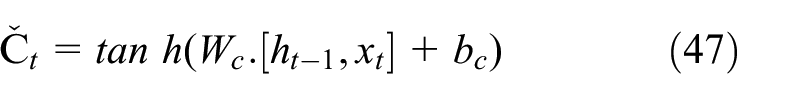
where tanh is an activation function.
Then calculate the value of the input gate, i t , and the value of the forget gate, f t using the following formulas:


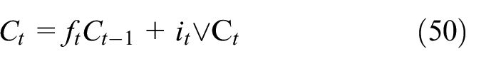
With σ being the sigmoid activation function, W i and W f representing the weights of the input gate and the forget gate, and b i and b f being the biases of the two gates respectively. Additionally, compute the value of C t using equation (47) where C t − 1 is the value of the LSTM at the previous time step. The process of updating the value of the LSTM is determined by the following equation (50):
Lastly, calculate the value of the output gate, denoted as O t , and subsequently feed O t into the activation function to obtain the value of h t .
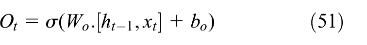

LSTM employs three special gates to manage the memory process of the network, thus addressing the issue of vanishing gradient values and retaining crucial data for longer periods. By virtue of its ability to store important data from the past, which influences the outcomes, the manuscript utilizes LSTM to preserve significant features that impact the prediction of financial data.
Evaluate research results
Constructing the motion model of the welding robotic arm optimized by the LSTM function is illustrated in Figure 9, with the motion function represented by equation (53).

Trajectory of the operational point of the welding robot arm with the optimized LSTM function.
To examine the results, we establish the motion rule of the final operation step over time t as follows:
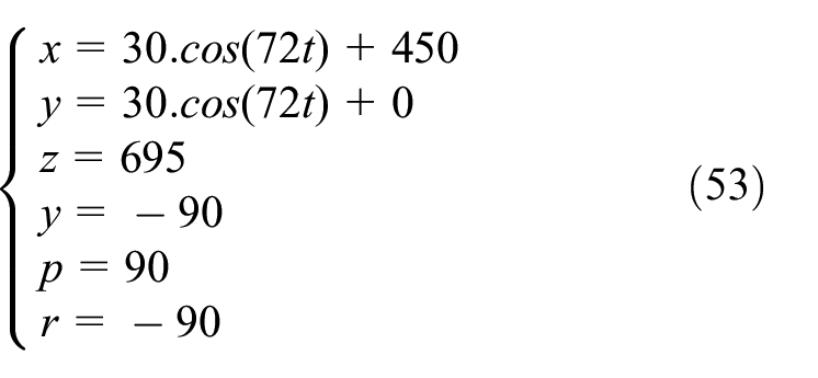
For t = 0…5, we obtained a table of angle values as computed, as shown in Table 2.
The obtained angle values q i through the computational process and the optimized LSTM function.
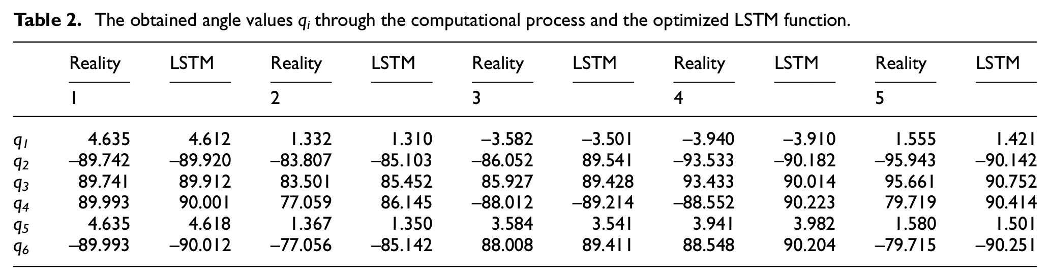
Clearly, the results from Table 2 demonstrate that the control process of the welding robot arm through the LSTM model yields significantly better outcomes compared to employing the conventional Cartesian coordinate control method. Consequently, the LSTM model has optimized the trajectories of the system points before control, ensuring the welding process is executed optimally. To verify the LSTM model through commonly used stopping functions, Table 3 presents the comparison of errors between the proposed LSTM models from this study and the widely used Cartesian models. The results indicate that the LSTM model is far superior to the Cartesian control process. With the nature of the robotic arm performing welding tasks for components, more precise control leads to improved safety and policies for the welded components.
Comparison of error measure between Descartes and LSTM model.

The accumulated errors of the welding points, using the proposed LSTM model from this study, are significantly optimized compared to the previously employed Cartesian model, as shown in Table 4. By substituting the obtained angular values into the Solidworks software, the research obtained trajectories, as depicted in Figure 10, using the five sets of rotation angles. This indicates that if a sufficient number of point values are taken, the LSTM model can accurately predict the positions where the robots perform welding. The study conducted two velocity surveys at two different positions of the robotic arm at distinct time points. The research then compares the displacement values at the vertices of the predicted trajectory through the LSTM model, as illustrated in Figure 11 and Table 5.
Comparison of results between Descartes and LSTM model.


Control model on the computer of the welding robot arm in a single-point welding state.

Velocity trajectory of the Descartes and LSTM models in the single-point welding state.
Actual control values and values obtained from the LSTM model in the single-point welding state.

Similar to case 1, when the welding robot arm scans into a point set (welding multiple consecutive points), the response of the robot’s velocity is depicted in Figures 12 and 13. The optimized calculations between the actual model and the LSTM model are shown in Table 6.

Control model on the computer of the welding robot arm in the trajectory welding state.

Velocity trajectory of the Descartes and LSTM models in the trajectory welding state.
Actual control values and values obtained from the LSTM model in the trajectory welding state.

The study will select five arbitrary points on the trajectory where the welding robots operate in reality as well as the trajectory interpolated and predicted by the LSTM model during the welding process. The results of each welding point are presented in coordinates along the three axes, as shown in Table 7.
A comparison table of the displacement values along the x, y, z axes of the actual welding point and the LSTM model.

Conclusion
The research on optimizing the welding robot’s motion model using the LSTM method from the draft has yielded several advantages over traditional control methods. This suggests that this model could lead to more accurate welding results, enhancing the economic efficiency during the execution process. Notably, the key advantages of this research include:
- The study has constructed a reverse control model of the welding robot for two welding cases: point welding and trajectory welding. This research model is novel due to the complex nature of operating multi-degree-of-freedom robots. The current control processes still exhibit considerable errors, making their practical implementation challenging.
- By combining the actual control process with the LSTM model from the draft, this approach has yielded novel results for this problem. The LSTM model from the draft can not only accumulate welding points from the past to execute current welding points but can also predict future welding points. The LSTM model has demonstrated significant advantages over the preceding models implemented in this study.
- In the future, the LSTM model from the draft could be integrated with various industrial robot models to enhance economic efficiency and improve the accuracy of robots during the working process.
Footnotes
Handling Editor: Sharmili Pandian
Author contribution
“I hereby declare that this submission is my own work and to the best of my knowledge it contains no materials previously published or written by another person, or substantial proportions of material. Any contribution made to the research by others, with whom I have worked in draft or elsewhere, is explicitly acknowledged in the draft.”
Declaration of conflicting interests
The author declared no potential conflicts of interest with respect to the research, authorship, and/or publication of this article.
Funding
The author received no financial support for the research, authorship, and/or publication of this article.