
Abstract
The investigation of stress distribution in an interference fit contact region is essential information required in fatigue and wear calculations to determine design life, regrinding requirements, and maintenance schedules. The aim of this work was to use ultrasound to non-destructively determine stress in the shrink-fit assembly, with the acoustoelastic theory. This one is based on the dependence of the propagation velocity of the ultrasonic wave with the stress state in the material. When a material is subjected to stress, there is a variation of the propagation velocity of the ultrasonic wave. Three methods have been initiated to ensure that the results will be more real, the first is the analytical calculation using thick-walled cylinder theory and Lamé formulation, then a numerical modeling of the contact between the assembled parts using finite element analysis and the third one is using elastic wave simulation and acoustoelastic theory in order to determine the value of the stress distribution at the interference region.
Keywords
Introduction
In the world of mechanical progress where the optimization is a recent subject, engineers tend to use simple, fast, efficient, and low-cost techniques. One of these techniques which is widely used in various field including aerospace, energy, agriculture, transportation, and medicine is the press fit assembly technique also known as interference fit. It consists in making an assembly with tightening between two parts, one called shrink (hub), the other shrunk (shaft). The main advantage supporting the development of this technique is because; it avoids the use of a part for the connection of the assembly, its non-destructive character, and the cost of its equipment.
This is why the attention of many researchers has been attracted to study the various parameters in which the strength of assembly depends on, 1 such as amount of interference, material properties, friction coefficient, 2 stress distribution, 3 surfaces roughness,4–6 form defects, 7 operating condition such as separation frequencies, 8 and the determination of stress at the contact surface. However, at this level we decide to use ultrasonic technique as non-destructive method based on the dependence of the propagation velocity of the ultrasonic waves with the stress in the material to analyze the stress distribution of cylindrical interference fit.
Ultrasonic waves testing uses mechanical waves which are similar to sound waves, but with a frequency range between 20 kHz and several hundred megahertz. They are a periodic phenomenon that propagates through a series of compressions and dilations of the medium of propagation. It is good to know that this wave is a disturbance of a medium, and not a displacement. The pressure variations of the vibrating molecules are mechanically transferred to neighboring molecules in a process called propagation. This process requires an elastic medium, unlike electromagnetic radiation, which can occur in a vacuum. This medium can be solid, liquid, or gas. Its utilization has several advantages, such as good accuracy, high speed, reliability, repeatability, affordability, and capability to use in several environments such as liquids. 9 Also, it is non-destructive and does not require direct contact with the part being tested. Finally, there is no limitation in terms of the type of material being tested or its geometric complexity (thin films or large components), and it is minimally influenced by temperature.10,11 Several aspects can be characterized by employing acoustic and ultrasonic waves: microstructure, defects (cracks, voids, inclusions, impurities, and porosity), mechanical properties, geometric accuracy, phase transition, acoustoelastic parameters, surface roughness, stress, and residual stress.12–14 The basis of acoustic and ultrasonic wave testing is the laws of acoustoelastic theory, which states that the determination of stresses by ultrasound is based on the dependency of the propagation velocity of the ultrasonic waves with the state of stress in the material. 15
This study focuses on the use of ultrasonic wave simulation in a shrink-fit assembly in order to determine the stresses at the contact interface between the shaft and the hub. For this purpose, a numerical modeling of the wave propagation and the theory of acoustoelasticity has been set up and the results obtained were compared with two other results, the analytical calculation using Lamé’s formulas and the numerical calculation of the stresses using the finite element analysis as shown below in Figure 1.

Study steps.
Studied structure
The model studied in this work and its geometric dimensions are shown in Figure 2, where the inner diameter of the hub remains constant, while the external one of the shaft changes in order to create a variety of cases in which the interference is not the same (Table 1). These cases will be treated in the next phase one by one with three different methods as already announced so that at the end the results will be compared.

3D model and geometric dimensions (in mm) of the studied assembly.
Studied cases and samples dimensions.

The mechanical properties of the steel material of the shaft and the hub are considered equal with Young’s modulus 210,000 MPa, Yield stress 504 MPa, Poisson’s ratio of 0.3, and density of 7800 kg/m3. 16
Stress calculation in press fit assembly
Analytical approach
The stress generated by this type of assembly techniques cannot be obtained or known directly, because at present, the value of the stress estimation at the interference fit contact region is based on the classical solution of thick-walled cylinder theory (TCT) that was announced in 1933, due to Lamé and Clapeyron, and developed in 1968 by Timoshenko.
17
The results of their work are used to calculate the stresses in a shrink-fit joint. The formulas relate the radial stress,

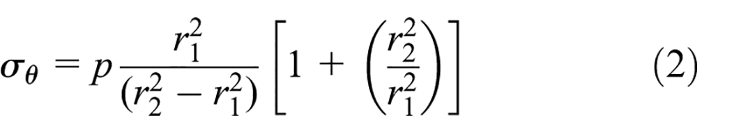

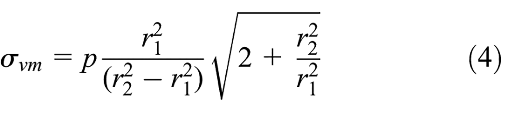
It is important to note that these formulas assume that the object and the hole have uniform properties and are perfectly cylindrical. In practice, there may be variations in the material properties and the geometry of the assembly, which can affect the accuracy of the stress calculations.
The interference


With

Shrink-fit parameters used to connect two parts.
Simulation of shrink-fitted joints
In order to verify the theoretical results and to set up another reference frame for the results of the acoustoelastic theory, a finite element analysis (FEA) was performed on a series of specimens with the same mechanical properties of the material. This step was based on investigating the effect of mesh size on the desired stress and strain results. Figure 4 shows the different cases treated to be able to come out with a convergence of results for a better choice of the element size.

Mesh study results.
The element size (mesh) used for the numerical analysis was 0.3 mm, in Figure 5, the curves show the influence of the element size on the stress and strain results. Several mesh sizes were treated in order to make a better choice for a better quality of the results. Going from 03 to 0.2 mm the stress interval was between 287.977 and 382.308 MPa with a relative error of 24.67%, for the deformation the interval is ranging from 0.12273% to 0.1555% with a relative error of 21.07%. For elements size of 0.5 mm the results converge to a constant value with an error of 1.31% for stress and 2.03% for deformation. On the other hand, elements with a size of 0.3 mm present a very low error of 0.09% and 0.32% for the stresses and strains, respectively.

Impact of mesh size on the interference fit stress.
The software employed for this analysis is ABAQUS, employing a nonlinear analysis for the contact elements. A static general interaction procedure with surface-to-surface contact (standard) was utilized, complemented by a finite sliding formulation. Furthermore, a normal behavior contact property was integrated to ensure realistic representation of normal contact behavior; the stresses have been evaluated in the linear elastic filed. The boundary conditions applied to the quarter part of the studied geometry, as illustrated in Figure 6, included constraining the shaft at its center of symmetry and the hub at the edges of its larger diameter. Additionally, the XSYMM condition (U1 = UR2 = UR3 = 0) and the YSYMM condition (U2 = UR1 = UR3 = 0) were uniformly enforced across the entire model. The element type used for the mesh is the C3D8R, which is an 8-node brick element suitable for three-dimensional structural analysis. It provides a balance between computational efficiency and accuracy through the use of reduced integration techniques. The FEA was performed on a simplified model (the fourth part of the original geometry) in order to reduce the computational time and to refine the mesh dimension.

Numerical model used in interference fit stress and strain calculation.
Usually the contact (Figure 7) is modeled by respecting the conditions of Signorini. This description remains however theoretical and does not correspond precisely to reality. It is not admissible from the mathematical point of view because the function linking the pressure and the contact is not bijective. It is therefore numerically not solvable. The law must then be modified to allow a regularization of the problem. To impose the contact condition, two techniques are regularly used, the penalty technique and the Lagrange multipliers technique.

Contact area between the hub and the shaft.
Elastic wave simulation
The simulation of the ultrasonic wave propagation was performed using the same commercial software used in press fitted joints calculation. This phase is based on the finite element method on a shrink fitted assembly in which the size of the used mesh is studied in relation to the transit time of the wave. Figure 8 shows that the ultrasonic response can be influenced by the chosen element size where the fine mesh is equivalent to a better presentation of the wave propagation.
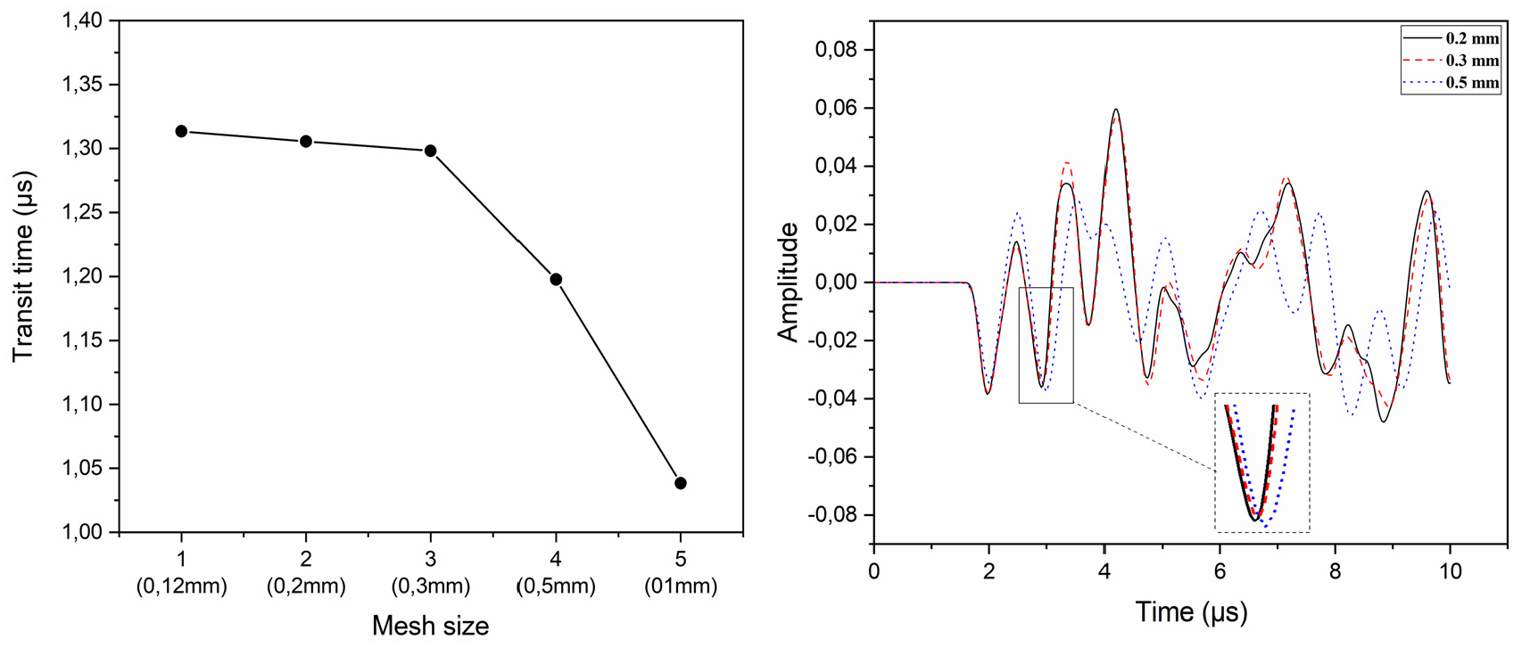
Transit time versus element size (left) and waveforms obtained for three different mesh sizes (right).
The mesh size used for the numerical simulation of the ultrasonic wave propagation was studied, while considering the frequency of 1 MHz, the wavelength is calculated at about 6 mm. In order to test the accuracy, simulations with different mesh sizes was performed. Figure 8 (right) shows the wave transit time from pulser to receiver measured by the first detectable disturbance of the received waveform. As the mesh size becomes finer (down to 0.12 mm) the measured transit time converges to the value of 1.31349 µs. The selected size of 0.2 and 0.3 mm, results in an error of 0.6% (1.30555 µs) and 1.15% (1.29828 µs), respectively. For the frequency of 1 MHz (period of 1 µs) more than 30 elements were used to describe the wave, with a stable time increment of 0.0712 µs. For the frequency of 5 MHz (period of 0.2 µs) the time step was 0.0555 µs still sufficing the requirement of at least 10 elements/wave length, while the wavelength was 1.2 mm, being 10 times longer than the mesh size, which is considered a minimum value to be respected so that the numerical presentation of the wave should be correct.18,19
The used material in this simulation is considered as linear-elastic, homogeneous, and isotropic. Boundary conditions were assumed as symmetry on (xz) plan and (yz). The numerical model was made of solid 8-node finite elements (C3D8R) with reduced integration. The longitudinal wave’s propagation problem was solved using dynamic explicit module. The total calculation time was assumed to be 10 µs with the time step equal to 1 × 10⁻⁷ s. The wave was excited by applying a pressure of a certain amplitude at the outer surface of the hub. The input signal was the same in all cases (Figure 9). The results of the analysis were recorded at the point of the contact surface and used in acoustoelastic theory to determine the stress and the strain of the assembly.

Excitation (left) and frequency (right) for elastic wave simulation.
Acoustoelastic theory
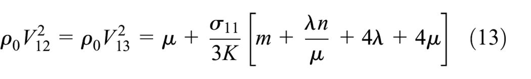
When a material experiences stress, such as in a shrink-fit assembly, and simulated ultrasonic waves pass through it, the analysis reveals fluctuations in the propagation speed and transit time of these waves, as per the simulation results (Figure 11). These variations are attributed to non-linear elastic effects formalized by Murnaghan 20 theory. Building upon this understanding, Hughes and Kelly 21 have demonstrated, through analytical formulas, how stress can be calculated using these variations in wave velocity. Specifically, they have shown that when an elastic wave propagates in an isotropic medium, the components of propagation velocity are determined by the following relationships:

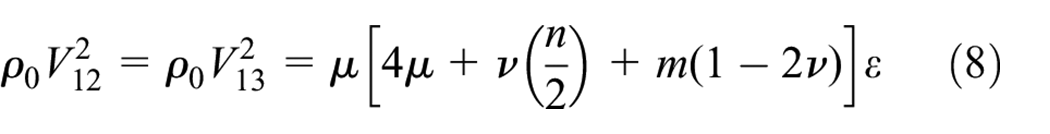
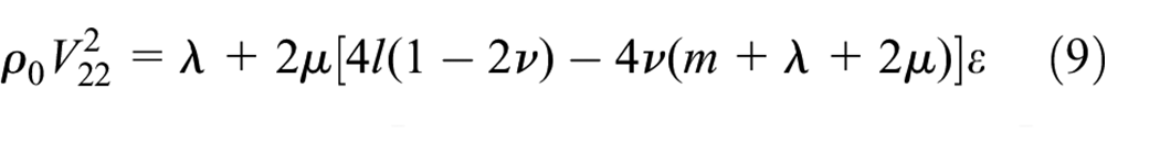


The propagation speed of elastic waves as a function of the existing stress in the propagation medium is presented in the formulas (12)–(16)


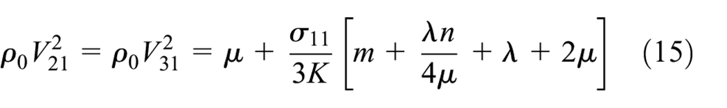


The first index of V and


Second- and third-order elastic constants. 16

Results and discussion
In order to understand the behavior of an ultrasonic wave propagating in an elastic solid medium in terms of displacement, snapshots of the displacement field of the wave with two different frequency values (01 and 05 MHz) are presented in Figure 10 where the contact area between the shaft and the hub is highlighted in red.
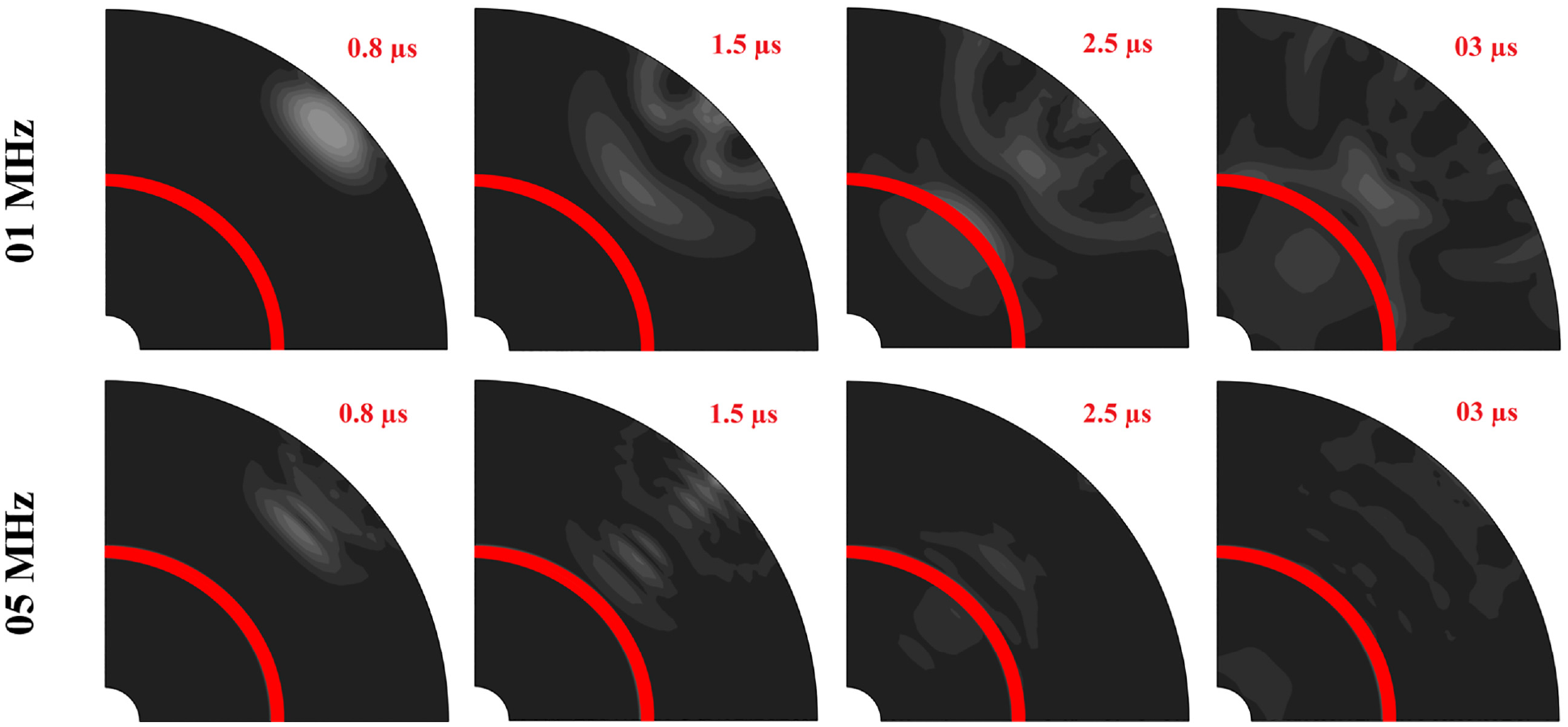
Snapshots of the ultrasonic wave displacement field with two different frequencies 01 and 05 MHz.
Four snapshots are displayed for each frequency experiencing the same contact stress, taken at different time intervals of 0.8, 1.5, 2.5, and 3 µs. It is observed that the waveform in the figures varies for the two frequencies, indicating that the wave transit time is not the same. The first step in Figure 10 corresponds to the generated wave at t = 0.8 µs, followed by an illustration of the waveform before reaching the contact surface of the assembly at t = 1.5 µs. The snapshots at t = 2.5 µs demonstrate the behavior of the propagating wave after crossing the contact area, where a portion of the wave is transmitted and the other is reflected.
The relationship between transit time of ultrasonic waves traversing a shrink-fit assembly and the stress at the interference fit contact region is graphically depicted in Figure 11. This figure illustrates how stress exerts a perceptible influence on the duration it takes for a wave to traverse a stressed medium. This phenomenon arises from the redistribution of material density within the stressed region, consequently engendering shifts in crucial mechanical properties like elastic modulus and Poisson’s ratio. Moreover, these stress-induced alterations extend to affect the material’s resistance to sound propagation, thereby impacting its acoustic impedance and, subsequently, the speed of sound propagation. Furthermore, stress interference introduces changes in the boundary conditions experienced by the ultrasonic wave, potentially leading to partial reflection and refraction at material interfaces. These altered wave behaviors collectively contribute to observable variations in transit time.

Simulated waveform (left), transit time of the wave propagation in a pre-stressed medium (right).
On the other hand, transit time is the most common measurement in ultrasonic technic, it is defined by the delay between the excitation when t = 0 µs and the first disturbance on the simulated waveform of the sensor (Figure 11). The influence of the wave frequency on its transit time of propagation in a pre-stressed medium is shown in Figure 11. For both cases of excitation frequency, we observe a tendency to increase the transit time with the stress at the contact interface, which is very smooth for 5 MHz. For this reason, this excitation frequency is used in the ultrasonic wave simulation to determine the relationship between the stress that exist in the shrink-fit assembly and the propagation speed of the US wave.
The results of the analytical method in terms of stresses and strains were obtained using thick-walled cylinder theory and Lamé formulas, based on several parameters such as the mechanical characteristics of the material, the contact pressure, and the interference between the two shrink fitted parts. These formulas have been used for a long time as a tool to understand the mechanical phenomena that may exist at the contact surface between the assembled parts. As well as simulation of contact that uses finite element analysis and consider the structure perfectly polished. This numerical method is used in many recent studies and shows the advantage of higher resolution models to understand interference-fits joints better.
In this work, the results obtained using these methods have been treated as references to which the acoustoelastic theory outcomes will be compared, Figure 12 show the evolution of these results as a function of contact interference of different used methods.
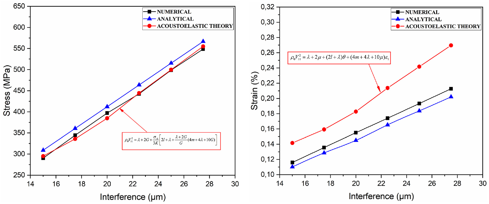
Stress and strain results of the used methods.
The relationship between interference value, stresses, and strains at the contact zone is directly proportional. The results obtained from the three methods used are presented in Figure 12, and they are quite similar, with the numerical stresses graph being the closest to that of the acoustoelastic theory. The interference between the two assembled pieces is the difference between the cases already mentioned in Table 1, which means that this interference generates different levels of stress and strain at the contact zone as indicated in Table 3. As a result, the transit time of the ultrasonic wave is affected and therefore its propagation speed.
Acoustoelastic theory results.

Acoustoelastic theory is a method used to model the behavior of elastic waves in materials under stress. It involves using the relationship between stress and strain in a material to derive equations for the change in wave velocity as a function of stress or strain. Acoustoelastic theory can be useful in predicting the behavior of waves in materials under stress and can provide insights into the effects of stress on wave propagation.
Conclusion
This study confirms the applicability of ultrasonic waves for stress assessment in prestressed materials, particularly in the context of shrink-fit assembly. The changes detected in the properties of ultrasonic waves, attributed to non-linear elastic effects, underline their usefulness in stress determination. Future work will include experimental tests to improve our understanding of stress distribution in press-fit assemblies, with further studies of surface roughness at the contact interface between two shrink-fitted parts and how this impacts on the behavior of ultrasonic waves.
Footnotes
Appendix
Notations

| interference | |
| von Mises stress | |
| hoop stress | |
| radial stress | |
| contact pressure | |
| , | inner radius of the hub |
| outer radius of the hub | |
| outer radius of the shaft | |
| speeds of waves propagating in the 1 direction with particle displacements in the 1, 2, 3 direction, respectively | |
| Stress that exist in the same propagation and oscillation direction of the ultrasonic wave | |
| and | Murnaghan’s third-order elastic constants |
| λ and µ | Lamé or second-order elastic constants |
| initial density | |
| Poisson’s ratio | |
| TCT | thick-walled cylinder theory |
| US wave | ultrasonic wave |
Declaration of conflicting interests
The author(s) declared no potential conflicts of interest with respect to the research, authorship, and/or publication of this article.
Funding
The author(s) received no financial support for the research, authorship, and/or publication of this article.