
Abstract
To address the challenges of applying air springs in high-speed rail vehicle ejections, the ejection of a driver’s cabin structure is focused on in this study, and an ejection simulation model of an air spring is proposed using a series-parallel combination. The model’s accuracy is verified through virtual collision analysis of the driver’s cabin in a rail vehicle. The ejection velocity exhibits a relative error of only 9.1%. The test vehicle, driven by an air spring, achieves a maximum kinetic energy of 415 kJ, meeting the initial target value of no less than 408 kJ. Additionally, the analysis of the wheel-rail interaction reveals that the vertical lift and lateral displacement of the test vehicle are within acceptable limits, measuring 5.49 and 9.89 mm, respectively, without exceeding the wheel flange height and tread width. These results demonstrate that an air spring with a series-parallel combination can successfully propel the test vehicle to conduct the driver’s cabin collision tests without any derailment or overturning. Research on the ejection performance of air springs in this configuration offers a new driving and ejection method for applying air springs in rail vehicles, drones, and air-launched missiles, presenting promising prospects for future applications.
Introduction
Due to the lack of rail vehicle ejection technology, it is difficult to carry out high-speed instantaneous ejection impact tests effectively. The excellent variable stiffness characteristics of air springs provide a practical technical means for the application of rail vehicles in the ejection field. Fundamental theoretical research on the impact of the air spring used for ejection is urgently needed. In the past few decades, finite element simulation technology has become an important means for studying the characteristics of air springs, making significant contributions to the rapid commercial application of air springs. Scholars from various countries have conducted systematic research and exploration in areas such as air spring inflation simulation, nonlinear characteristics, and structural parameter optimization.1,2 In particular, exploration in the field of ejection has provided a new direction for studying air springs.
Rubber, which is a popular hyperelastic material, has always been challenging to studying current research due to its nonlinear characteristics. Air springs, which are composite materials composed of reinforcement cords and a rubber matrix through effective composite technology, have nonlinear mechanical properties that are difficult to simulate accurately using existing models, especially their dynamic characteristics. In terms of nonlinear theoretical formulations, Zargar et al. 3 developed a nonlinear theoretical model and validated the correctness of their mathematical model through experiments. Apart from theoretical derivation, researchers have used the derived nonlinear hyperelasticity model to obtain conclusions on the dependence of the air spring stiffness on the frequency and excitation amplitude. 4 More research has been conducted on the dynamic stiffness characteristics using numerical models, simplified models, and experimental tests.5,6 Zhu et al.7,8 validated the proposed models through experimental tests, demonstrating the accuracy of predicting the nonlinear dynamic characteristics under large amplitude excitation and different precompression and pre-stretching conditions. Regarding the study of cord parameters, the focus has primarily been on modifying the tensile formula of the rubber cord material parameters, conducting theoretical derivations of numerical models, and developing simplified models.9,10 The focus of the nonlinear theoretical research on air springs mainly been on the vibration and cushioning fields. The aforementioned research achievements have played a significant role in promoting the rapid application of air springs in suspension fields. However, further in-depth research on the nonlinear dynamic theory of air springs is needed.
Air springs, which are commonly used components in two-stage suspension systems connecting the bogie and the car body of railway vehicles, play an important role in effectively filtering the vibrations transmitted from the wheel-rail interactions to the car body structure. Scholars have conducted research on the vehicle straight-line stability and safety during curve negotiations with respect to air springs. 11 Mazzola and Berg 12 proposed a method combining indoor tests and model identification techniques to accurately define the air spring model. Qi et al. 13 focused on the air springs of high-speed trains, identified the parameters of a fractional-order model based on measured data, and established a fractional-order modified model to optimize the aerodynamic model. Ryaboy 14 investigated the vertical dynamic characteristics of air springs and further analyzed the stability of vibration isolation systems composed of multiple air springs. Facchinetti et al. 15 compared and analyzed two modeling methods for a two-stage air spring suspension and evaluated their influence on the accuracy of multibody dynamic simulations of rail vehicles. Furthermore, research on the construction method of equivalent models for air springs is also a current focus. This research is mainly conducted through experiments and theoretical analysis to obtain equivalent load curves and derive analytical solutions for air spring stiffness.16,17 Studies on the vertical, lateral, and torsional stiffness characteristics of air springs have focused primarily on physical geometric parameters, 18 cord ply parameters, 19 fluid mechanics parameters, 20 and so on. Bhattacharyya et al. 21 investigated the impact of linearizing the air spring stiffness on the damper performance and provided frequency variations of dampers with different design parameters.
In recent years, domestic and international research and development institutions have successively developed experimental driving devices for the collision testing of railway vehicles using hydraulic and pneumatic cylinder driving methods. These devices allow for impact collision tests on rail test rigs, driver cabins, and components. However, there are common disadvantages such as long response times for hydraulic-driven impacts, the generation of sonic booms by cylinder driving, and poor control accuracy of the ejection impact velocity. Air spring ejection, which is a new driving method, can overcome these drawbacks. However, research on the ejection impact performance of air springs is still relatively limited. Li et al. 22 conducted impact tests on two types of self-inflating air springs and obtained the relationship between the maximum pressure of the air springs and the initial landing velocity and load mass. Ma et al. 23 studied the dynamic response characteristics of sealed air springs under different impact types and pressures. The experimental data showed that air springs can absorb and transfer impact energy through deformation and release impact energy through multiple dynamic response cycles of loading and unloading. In terms of air spring ejection research, Xiao first proposed a collision testing method based on pouch-type rail vehicle propulsion. This method transforms the traditional work done by cylinders into work done by air springs to achieve ejection acceleration of the test rig. 24 Li et al. 25 used the CV method to establish a finite element model for air spring ejection and obtained the influence of parameters such as the gas mass flow and wall thickness on ejection performance through simulation analysis. To further study the impact of cord parameters on ejection performance, Li et al. established a dynamic ejection model for air springs based on the surface fluid element method. Through simulation analysis, they determined the influences of the cord parameters on the ejection performance and static load characteristics. They also discovered the phenomenon of impact instability during the acceleration of the test rig in ejection impact tests. 26 The series-parallel combination of air springs can achieve long-distance and high-thrust ejection impact tests on rail vehicles and component-level elements. Therefore, it is necessary to conduct research on the ejection performance of air spring based on series-parallel combinations to provide theoretical support for the application of air springs in the field of ejection.
Based on the theories of gas–solid coupling, thermodynamics, and collision dynamics, an air spring ejection model is established in this paper. Finite element numerical simulation is used to analyze the influence of the series-parallel combination method on the ejection performance of the air spring. Subsequently, a prediction model for the elastic performance of air springs based on series/parallel combinations is constructed. The correctness of the air spring ejection performance prediction model is further verified through a virtual collision simulation analysis of the driver cabin of a rail vehicle as a case study.
Representation of an air spring series-parallel combination
Series-parallel combinations of air springs
To enhance the ejection speed of the air spring, it is proposed to improve the ejection performance by changing the combination of air springs in series and parallel. The combination forms mainly include single-stage series connections and multistage parallel connections of air springs. The series connection form of the air springs is shown in Figure 1, with Levels 1, 2, 3, 4, and 5 in series, as well as Levels 1, 2, 3, 4, and 5 in parallel. Considering factors such as the connection between the air spring and the cylinder and the size of the cylinder’s diameter, the maximum number of parallel stages for the air springs is set to 5.

Schematic diagram of air spring series and parallel combinations.
By combining the series and parallel connections, the air springs can be arranged in a serial-parallel combination. Based on the energy level requirements in different collision scenarios, a representation method for the serial/parallel combination of air springs is provided. The combination representation is denoted as T ij , where i = 1, 2, 3, 4, 5 and j = 1, 2, 3, 4, 5. The minimum combination is T11, and the maximum combination is T55, resulting in a total of 25 combination forms. The three-dimensional combinations of T31, T32, T33, T34, and T35 are shown in Figure 1.
Ejection model
The air spring ejection model consists of an air spring, a cylinder, and a test vehicle, among others. In this study, the ejection air spring is composed of a single-curved bag in a three-stage series, denoted as T3*1, forming a relatively enclosed air spring cavity between the curved bags. One end of the air spring is connected to a fixed cylinder, while the other end contacts the test vehicle. By compressing the air spring with a certain displacement Δd = 20 mm, the initial geometric parameters of the air spring are ØD = 220 mm, L = 22 mm, and Ød = 132 mm, and the initial length H is 300 mm. High-pressure gas is introduced into the cavity, propelling the test vehicle to accelerate in the X direction during ejection. The Mooney–Rivlin model was used for the airbag material, and the material parameters are shown in Table 1 and Figure 2.
Material parameters of air spring.


Schematic diagram of air spring ejection.
The key parameters established in the air spring ejection model include ambient pressure (P a ), air spring chamber pressure (Pc), chamber volume (V), chamber temperature (T), and the effective contact area of the air spring. The effective contact area is defined as a displacement function in the X direction.

Air spring exhibit variable stiffness characteristics under different gas pressures, and during the ejection process, there are deflection and force transmission in the X, Y, and Z directions. 27 Among them, the axial force in the X direction plays a crucial role in the ejection of the air spring. The ejection force F a is expressed as

In the absence of gas exchange between the air spring and the external system, based on the laws of thermodynamics, according to the ideal gas equation, it can be understood that

In the equation, for isothermal conditions, n = 1; for adiabatic conditions, n = 1.4; for variable conditions, 1 < n < 1.4.
The initial pressure P0 and initial volume V0 of the rubber bladder chamber, when the pressure is P, the chamber volume V is given by

Differentiating equation (4) with respect to x yields the following equation
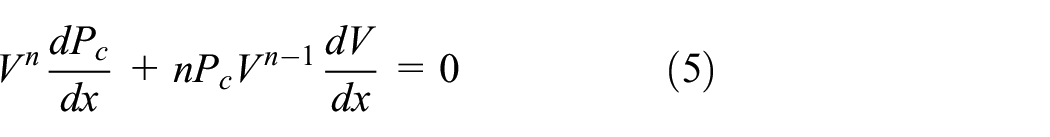

Differentiating equation (2) and substituting equation (6) yields the following relationship between non-linear elastic stiffness, force, and displacement of the rubber bladder.

Fluid–structure coupling method
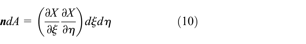
The fluid–structure coupling method is an important part of the simulation analysis of air spring ejection impact. It has significant importance in simulating the interaction between the structure and the gas during inflation. It is primarily achieved through the fluid chamber model, fluid model, and adiabatic process. The axial load on the air spring depends not only on the geometric nonlinearity, material nonlinearity, and contact nonlinearity 28 but also on the pressure changes in the chamber. A finite element method is used to establish a shell element model for the bladder structure, while a surface-based fluid modeling method is employed to simulate inflation inside the rubber bladder. The surface-based fluid elements share nodes with the bladder structure, and when reference points are associated, the fluid elements transform into solid elements.
The coordinates of the fluid element nodes are given by

In the equation, N i represents the shape function of the fluid element, which is expressed in terms of the isoparametric coordinates ξ and η. X i (x, y) represents the coordinates of the reference points.
The Jacobian matrix of the fluid element is given by

By using the outward normal vector of the fluid element
By using the elemental area, we can obtain the elemental volume as
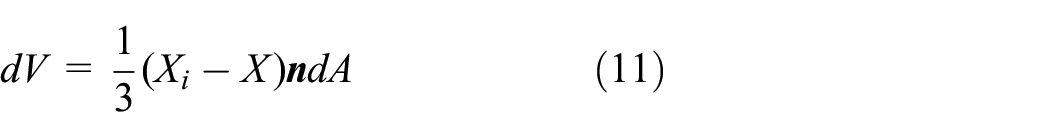
By integrating over the elemental volume, we can obtain the volume of the fluid element as

Since all the elements in the chamber have the same temperature, the fluid volume of each element can be calculated using the following equation

Where
The gas volume can be expressed as

Then the fluid density

Where
By combining equations (14) and (15), the pressure-volume relationship inside the gas chamber of the air spring can be obtained.

Air spring ejection performance
Ejection velocity
Based on a single air spring, the air springs are connected in series with Levels 1, 2, 3, 4, and 5. In addition, on the basis of a 3-level series connection, they are connected in parallel with Levels 1, 2, 3, 4, and 5. The parameters of each level of the air spring are the same during the series-parallel connection process. Under the conditions of an initial pressure of 0.1 MPa, an initial compression displacement of 20 mm, and an ejection mass of 113 kg, the ejection performance of the air spring is obtained by changing the number of series-parallel connections.
According to Figure 3(a), the ejection velocity increases with an increase in the number of series-connected air springs. The initial ejection velocity of the 1-level series-connected air spring (before 0.15 s) is significantly different from the ejection velocities of the other series connection levels. In addition, there is a noticeable decrease in the increase in the ejection velocity for the 5-level and 4-level series-connected air springs. This indicates that once the series connection level reaches a certain value, the ejection velocity will not exhibit significant improvement, and the incremental increase in ejection velocity shows a decreasing trend. As shown in Figure 3(b), the ejection velocity of the air spring increases with an increase in the number of parallel-connected levels. It is evident that changing the parallel connection level from 1 to 5 significantly enhances the ejection performance of the air spring. Simultaneously, the ejection time decreases from 0.20 to 0.145 s. However, when the number of air spring levels reaches 5, there is a decrease in the increase in the ejection velocity, and the rate of increase in the ejection performance decreases. Therefore, it can be concluded that increasing the number of series-parallel levels of the air spring can enhance the ejection velocity and subsequently improve the ejection performance. However, the incremental increase in the ejection velocity decreases as the number of levels increases.

(a) Ejection velocity of air spring with different series levels and (b) Ejection velocity of air spring with different parallel levels.
Ejection load
To investigate the reasons for the influence of series-parallel levels on the ejection velocity of the air spring, further research was conducted on the variation in the ejection force and chamber pressure with changes in the series-parallel levels. Based on the ejection model of the air spring, a finite element numerical simulation was employed to determine the variation in the air spring during the ejection process, as shown in Figure 4(a) and (b). To study the effect of series/parallel levels on the chamber pressure of the air spring, the change process of the chamber pressure over time for different series-parallel levels of the air spring was obtained, as depicted in Figure 4(c) and (d).

Influence of series-Parallel levels on the ejection load of air spring. (a) is the change of ejection force of different series air springs ejection with time, (b) is the change of ejection force of different parallel air springs ejection with time, (c) is the change of chamber pressure of different series air springs ejection with time, (d) is the change of chamber pressure of different parallel air springs ejection with time.
Figure 4(a) shows that during the initial stage of ejection, the ejection forces of the air springs with different series connection levels have a similar range of variation. However, in the middle and later stages of ejection, the ejection forces increase with the corresponding increase in the series connection levels. At the same time, the duration of the air spring action also increases, leading to more significant differences in ejection force during this stage. The ejection force trends and ranges of the 4-level and 5-level series-connected air springs are similar, with only slight differences in ejection force occurring near the end of ejection. This may be the reason for the smaller variation in the ejection velocity between the 5-level and 4-level series-connected air springs. According to Figure 4(b), the ejection forces of the air springs increase with an increase in the parallel connection levels. However, as the parallel connection levels increase, the ejection duration decreases. The greater the parallel connection level is, the shorter the ejection duration. Therefore, it can be concluded that the reduction in the ejection duration of the air spring due to increasing parallel connection levels leads to the ejection velocity not increasing correspondingly with the increase in parallel connection levels.
Figure 4(c) shows that the pressure in the chamber of the air spring decreases rapidly when connected in a 1-level series, stabilizing at approximately 0.054 MPa after the ejection is completed. When connected in a 2-level series, the pressure in the chamber fluctuates around 0.072 MPa. For other series connection levels, the air spring pressure fluctuates approximately 0.078 MPa. This indicates that the higher the series connection level is, the greater the residual pressure in the chamber. However, for 3-level and higher series connections, the residual chamber pressure is similar and changes minimally. This may be due to the smaller influence of the volume change caused by compression displacement on the chamber volume of the air spring with higher series connection levels. Figure 4(d) shows that different parallel connection levels have minimal impacts on the final chamber pressure, with fluctuations occurring within the same range. They only affect the rate of pressure decrease, with a higher parallel connection level resulting in a faster decrease in the chamber pressure. Therefore, this is an important factor causing a shorter ejection duration when using a greater number of parallel connections for the air spring.
Through the discussion of the ejection velocity and ejection impact force of the air spring, it can be seen that in addition to the initial pressure, compression and other parameters of the air spring, the series number and parallel number also have an important influence on its ejection effect. The observation that the addition of series-parallel combinations tends to enhance ejection performance, but the increase becomes gradually less significant, is intriguing. Rubber with cord reinforcement exhibits nonlinear characteristics. On one hand, its elastic capacity does not linearly increase with the increase of the air spring’s impact load, resulting in a negative correlation. This leads to the non-linear increase in ejection performance of the air springs as the number of series and parallel combinations increases. The ejection impact force increases with the increase in the number of series and parallel combinations. However, the air spring is a strong nonlinear rubber material, and its elastic properties increase nonlinearly with the increase in impact load, sometimes even decreasing slightly. Moreover, as the impact load increases, the action time of the air spring decreases, further reducing the rate of increase in ejection speed.
To avoid this situation, the ejection performance of the air spring can be significantly improved by establishing a guide device and increasing its initial compression capacity to further increase the effective action distance, and then by increasing the ejection action time and distance. The potential avenues will be beneficial for further research to improve the ejection performance.
Ejection performance prediction model
Problem description
The combined series-parallel configuration of air spring provides greater ejection kinetic energy, allowing for the selection of air spring series-parallel combination parameters based on different energy configurations. Considering factors such as the air spring stroke and footprint, a maximum number of series connections, n ≤ 3, and a maximum number of parallel connections, c ≤ 3, are set in this study. Based on the optimized geometric parameters of the air springs, the aim is to establish a functional relationship, f(D, P, n, c, Ek), between the diameter of the toroidal air spring (D), the chamber pressure (P) the number of series connections (n), the number of parallel connections (c), and the ejection kinetic energy (E k ). Factors such as the compression displacement (d), and air spring wall thickness (t), which have minimal impacts on the ejection performance, are disregarded. The wall thickness of the air spring is set to 8 mm, the initial compression displacement is 100 mm, and the ejection mass is 1000 kg. The ejection kinetic energy (E k ) is defined as follows:

In this equation, m represents the ejection mass, and v represents the maximum ejection velocity.
The constraint conditions for air spring ejection parameters are as follows.

In this equation, both n and c are integers. In the optimization of series-parallel parameters, the ejection velocity, Y is taken as the optimization objective.
Based on the constraint conditions of design variables, the optimization problem for air spring series-parallel parameters is defined as follows

To optimize the air spring series-parallel parameters, first, an ejection performance surrogate model is established for the series-parallel parameters. The objective is optimized and solved to obtain the optimal combination of air spring ejection parameters.
First, the fitting of the air spring series-parallel parameters is performed to obtain the ejection velocity (Y), for the four parameter combinations. Then, the surrogate model is optimized and solved. A total of 45 experimental samples were obtained through the design of experimental (DOE), as shown in Table 2.
DOE samples.

Construction of the prediction model
A surrogate model is a mathematical model used to address the complexity of physical models in engineering practice. It typically approximates or fits discrete data using interpolation or approximation methods. To obtain accurate and efficient optimization results, surrogate models are often used to replace actual models while ensuring model accuracy. Commonly used methods include the response surface methodology (RSM), 29 kriging model (KRG), 30 support vector regression (SVR), 31 radial basis function (RBF) models,32–34 artificial neural network (ANN) models, and orthogonal polynomial models, among others. With advancements in science and technology, these models are increasingly being developed and applied in multidisciplinary optimization design.
The following process was employed in this paper to construct the surrogate model: (1) First, design variables were proposed for the physical problem at hand, and the constraint conditions of the design variables were established through experimental design to obtain the experimental samples (i.e., input data for the model). (2) The experimental samples were computed to obtain the corresponding response data (i.e., the model output data). (3) The input and output data were fitted using the surrogate model construction method to establish a surrogate model relating the design variables and responses. (4) The obtained surrogate model was cross-validated to determine whether it met the required accuracy. If the requirements were satisfied, the desired surrogate model was output; otherwise, a new experimental design was used.
To determine the relationships between the different parameters and the ejection velocity and to determine the ejection velocity of the air spring based on input parameter values, a second-order RSM was used to fit the 45 experimental samples. The most commonly used polynomial response surface (PRS) model is a second-order algebraic polynomial function.
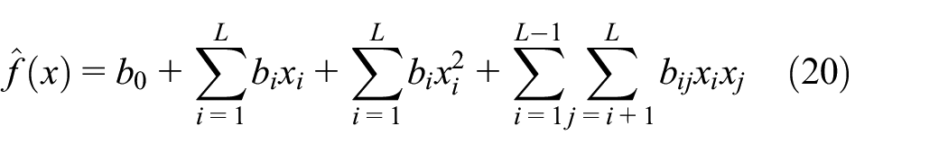
In the equation,
Based on the proposed PRS methodology, an approximate fitting equation was obtained through least squares regression of the input and output parameters. Depending on the complexity of the model, linear, quadratic, cubic, and quartic polynomials were selected for fitting. In this paper, a cubic polynomial response surface methodology was adopted. By using the input experimental sample points, four input parameters (D, P, c, n) and one output parameter Y were established. A cubic polynomial model was employed for fitting and optimization. For the error analysis, a fifteen-sample cross-validation was conducted. In the cross-validation error analysis, some data points were removed from the sampling dataset, and these data points were used to validate the accuracy of the predicted results. These points were selected randomly to improve the evaluation accuracy of the model.
A total of 10 cubic response surface approximation models were fitted, and the surrogate model for air spring ejection velocity is represented by the following equation.

By substituting equation (17) into equation (21), we obtain the predicted performance model for air spring series-parallel combinations.

From equations (20)–(22), the determination coefficient R2, average relative error (ARE), and maximum relative error (MRE) of the surrogate model for air spring ejection kinetic energy can be obtained. The accuracy of the air spring ejection performance prediction model is shown in Table 3.
Accuracy of air spring ejection performance prediction model.

Table 2 shows that the average error and maximum relative error of the air spring ejection performance prediction model established based on the response surface method are 0.0711 and 0.183, respectively. These values meet the accuracy requirements of having an average error less than 0.2 and a maximum error less than 0.3.
Considering the determination coefficient R2 =0.912 > 0.9, as shown in Table 2, the cross-validation results of the above prediction model indicate that the constructed prediction model for the air spring series-parallel parameter ejection performance meets the accuracy requirements. It can provide a predictive analysis for the actual air spring ejection performance.
Parameter influence
To investigate the response relationship between the ejection velocity Y of the air spring and the initial pressure P, the diameter of the curved sac D, the series number n, and the parallel number c, a response analysis was conducted using an ejection performance prediction model. The results, depicting the response relationship between the ejection velocity and different parameters, are shown in Figure 5.

(a) The response relationship of ejection velocity Y with series number n and parallel number c. (b) The response relationship of ejection velocity Y with initial pressure P and curved sac diameter D. (c) The response relationship of ejection velocity Y with parallel number c and curved sac diameter D. (d) Figure 16 illustrates the response relationship of ejection velocity Y with series number n and curved sac diameter D. (e) The response relationship of ejection velocity Y with parallel number c and initial pressure P. (f) The response relationship of ejection velocity Y with series number n and initial pressure P.
According to Figure 5(a), when the initial pressure of the air spring is 0.1 MPa and the diameter is 500 mm, the ejection velocity shows a nonlinear characteristic with respect to both the series number and parallel number. With a parallel number of 3, the ejection velocity increases with an increase in the series number. However, when the parallel number is 1, the ejection velocity decreases with an increase in the series number, forming two peaks. Therefore, having more parallel and series numbers is advantageous for enhancing the ejection performance of the air spring.
Figure 5(b) shows that overall, the ejection velocity of the air spring increases with increasing initial pressure and curved sac diameter, revealing a significant and positive correlation. The maximum ejection velocity is achieved when both the initial pressure and curved sac diameter are at their maximum values. However, when the initial pressure is at its minimum, there is a fluctuation in ejection velocity as the curved sac diameter increases, and the increase in velocity is not significant. This may be attributed to a mismatch between the larger curved sac diameter and the lower initial pressure, leading to instability in the ejection process of the air spring.
According to Figure 5(c), when the initial pressure is 1.0 MPa and the series number is 1, the ejection velocity of the air spring significantly an increasing with an increase in the curved sac diameter but decreases with an increasing parallel number. The maximum ejection velocity is achieved when the initial pressure is at its maximum and the parallel number is at its minimum. This indicates that increasing the parallel number is not conducive to improving the ejection velocity, especially when the curved sac diameter is 500 mm, where the ejection velocity is the lowest for a parallel number of 3.
According to Figure 5(d), when the parallel number is 1 and the initial pressure is 0.1 MPa, the ejection velocity of the air spring is positively correlated with both the curved sac diameter and series number. The air spring achieves the maximum ejection velocity when both the series number and the curved sac diameter are at their maximum values. Overall, the ejection velocity of the air spring increases with increasing series number and curved sac diameter. However, when the curved sac diameter is 500 mm, it exhibits a negative correlation with the series number, meaning that a higher series number leads to a lower ejection velocity.
According to Figure 6(e), when the series number is 1 and the curved sac diameter is 500 mm, the ejection velocity of the air spring significantly increases with increasing initial pressure. The parallel number has some influence on the ejection velocity, but the effect is relatively small. At a certain initial pressure, the ejection velocity of the air spring increases with a decreasing parallel number, although the improvement is not very significant.

Virtual collision model of vehicle end driver’s cab.
According to Figure 5(f), when the parallel number is 1 and the curved sac diameter is 500 mm, the ejection velocity of the air spring significantly increases with an increasing initial pressure and series number, showing a positive correlation. The maximum ejection velocity is achieved when the initial pressure is 1.0 MPa and the series number is 3.
Series-parallel combination scheme
Based on the collision energy requirements of EN15227, various series-parallel combinations are used in conjunction with changes in the curved sac diameter and initial pressure in the chamber to provide the desired collision kinetic energy. The collision energy requirements for the anti-climbing energy-absorbing device, car end underframe, and car end driver cab are shown in Table 4.
Collision energy requirements design.

After obtaining the surrogate model f(D, P, n, c, v) for the ejection performance of the air spring, optimization is performed by considering the series-parallel parameters of the air spring. The constraints are defined as shown in equation (23).

After setting the constraints, selecting the optimization algorithm, and defining the optimization objective for the ejection velocity of the air spring, optimization solutions are obtained for three different collision scenarios. The parameter solutions for the anti-climbing energy-absorbing device, vehicle end underframe, and vehicle end driver cab structures are presented in Table 5.
Parameters of air spring ejection performance.

Based on the established predictive model for air spring ejection performance, different combination schemes for series-parallel air spring ejection parameters can be obtained by setting constraint conditions to meet the collision energy requirements of different levels. The combined parameters of air spring ejection performance under these operating conditions will be used in virtual collision tests driven by air spring ejection. This will provide technical support for the establishment of a virtual collision test platform based on an air spring ejection drive.
Collision case numerical analysis of vehicle end driver cab
The vehicle end driver cab is located at the front end of the vehicle and mainly consists of the front-end frame of the driver cab and the underframe. It deforms to absorb the collision energy of the vehicle while ensuring the safety of the driver. It plays an important role in train collision safety. The virtual collision analysis model of the test platform was established in ABAQUS/EXPLICIT analysis software. This model uses a workstation for virtual collision testing, which is based on finite element simulation calculations. It uses 30 cores for parallel computing and 128 GB of running memory. The calculation parameters of specific conditions are shown in operating conditions 3 in Table 5.
The established virtual collision analysis model for the vehicle end driver cab with air spring ejection is shown in Figure 6. It mainly consists of rigid walls, a vehicle end driver cab, mounting brackets, connecting plates, connecting frames, a test trolley, air springs, cylinders, cylinder supports, braking devices, tracks, and sleepers. The driver cab is connected to the connecting plate using bolts, the connecting plate is connected to the mounting bracket using bolts, and the mounting bracket is securely connected to the test trolley through a bolted connection interface. The flange height of the wheels of the test trolley is 9.5 mm and the tread width of the wheel is 45 mm.
The rigid walls, cylinder supports, braking devices, tracks, and sleepers are constrained to simulate the static state of the collision test. The contact between the components is modeled using a surface-to-surface contact algorithm, while the air springs and large deformations of the driver cab are modeled using a single-sided contact algorithm with a friction coefficient of 0.15. The parameters of the air spring in the finite element simulation model are set according to the virtual collision test parameters of the vehicle end driver cab structure, as shown in Table 4, for Operating Condition 3. The requirement is to achieve a collision energy of 408 kJ for the driver cab.
Collision response
The deformation pattern of the vehicle end driver cab structure is shown in Figure 7. The collision begins at 0.645 s. During the process of collision and crush deformation, the front structure of the driver cab first makes contact with the rigid wall. As the collision progresses, the front weak area starts to collapse and crush, and both the cab frame and the end chassis undergo plastic deformation. During the collision, the end structure undergoes partial elastic deformation and the stress gradually decreases. At a collision time of 0.80 s, the driver cab is completely detached from contact with the rigid wall and begins to rebound.

Collision deformation pattern of the driver’s cab structure.
The air spring-driven test trolley exhibits a velocity–time relationship, as shown in Figure 8(a). The total kinetic energy of the system changes with time, as depicted in Figure 8(b). The internal energy absorbed by the driver cab after impacting the rigid wall varies with the displacement of the test trolley, as shown in Figure 8(c).

(a) Test trolley speed with time, (b) Total kinetic energy with time and (c) Internal energy of the driver’s cab with time.
Figure 8(a) shows that 15.41 t test trolley and driver cab driven by the 1.20 MPa initial pressure air spring reach a maximum velocity of 7.33 m/s (approximately 26.40 km/h). The ejection process of the vehicle-end driver’s cabin structure can be divided into three stages: air spring compression, air spring ejection, and friction deceleration. At 0.645 s, the front end of the driver’s cabin structure makes contact with the rigid wall. By 0.845 s, the driver’s cabin reaches maximum compression, and some structures begin to elastically recover. The speed of the test trolley then rebounds, eventually reaching a maximum rebound velocity of −1.22 m/s.
Figure 8(b) shows that the air spring propulsion test trolley reaches its maximum kinetic energy of 415 kJ. The reduction in kinetic energy before 0.645 s is primarily attributed to friction between the wheels and the rails, accounting for 68 kJ of energy consumption during this period. Between 0.645 and 0.745 s, the energy consumption is 13 kJ. Later, as the cart separates from the rigid wall, the main energy consumption is attributed to the significant deformation energy at the front end of the driver cab. Subsequently, the driver cab rebounds and separates from the rigid wall at a certain velocity, ultimately consuming the remaining energy through friction.
Based on Figure 8(c), the maximum internal energy absorbed by the structural deformation of the driver cab after colliding with the rigid wall is 321 kJ. As certain structures elastically recover, the internal energy of the driver cab decreases and is converted into the rebound kinetic energy of the test trolley. The driver’s compartment structure experiences a maximum deformation of 321 mm, and the internal energy of the driver’s compartment is primarily generated by crushing deformation during this stage.
According to Table 6, the predicted ejection velocity given by the air spring ejection prediction model is 8.0 m/s, while the ejection velocity obtained through finite element simulation is 7.33 m/s. The relative error between the two is only 9.1%. The correctness of the ejection model finite element simulation of the air spring was verified in the Ref. 26 This indicates that the established air spring ejection prediction model yields reliable results and can be used for the combined optimization design of air spring to propel high-mass, high-speed instantaneous ejections.
Ejection performance parameters.

Wheel-rail contact relationship
For the air ejection test trolley, its wheel rail relationship includes the vertical lift and lateral offset of the wheels. The wheel-rail vertical rise and lateral offset during the ejection process are the important preconditions to measure whether the rail vehicle is derailed. Non derailment during the ejection process is an important prerequisite for achieving higher speeds of rail vehicles for ejection. Therefore, the wheel-rail relationship in ejection process of the test trolley is of great significance for the air spring to further push the ejection of the rail vehicle.
Regarding train crashworthiness standards, the main ones include British standard GM/RT2100, European standard EN15227, and American standard CFR49. Meanwhile, France, Japan, Germany, and South Korea have defined train accident collision scenarios. Among these, EN15227 is the most widely recognized and commonly utilized rail wheel crashworthiness design standard, adopted by numerous countries. The EU EN 15227 collision standard sets a limit on the vertical lift amount of the wheel, requiring that at least two wheelsets on different bogies of a vehicle have a vertical lift amount not exceeding 75% of the nominal rim height.
Figure 9(a) shows the variation in the wheel-rail contact forces during the air spring ejection collision process of the test trolley, including both the vertical and lateral contact forces between the wheel and rail. To analyze this, four measurement points were placed at the wheels of the test trolley, enabling us to obtain the time-dependent vertical lift of the wheelsets through virtual collision analysis, as depicted in Figure 9(b). Furthermore, Figure 9(c) shows the time-dependent variation in the lateral displacement of the wheelsets, which was obtained through virtual collision analysis.
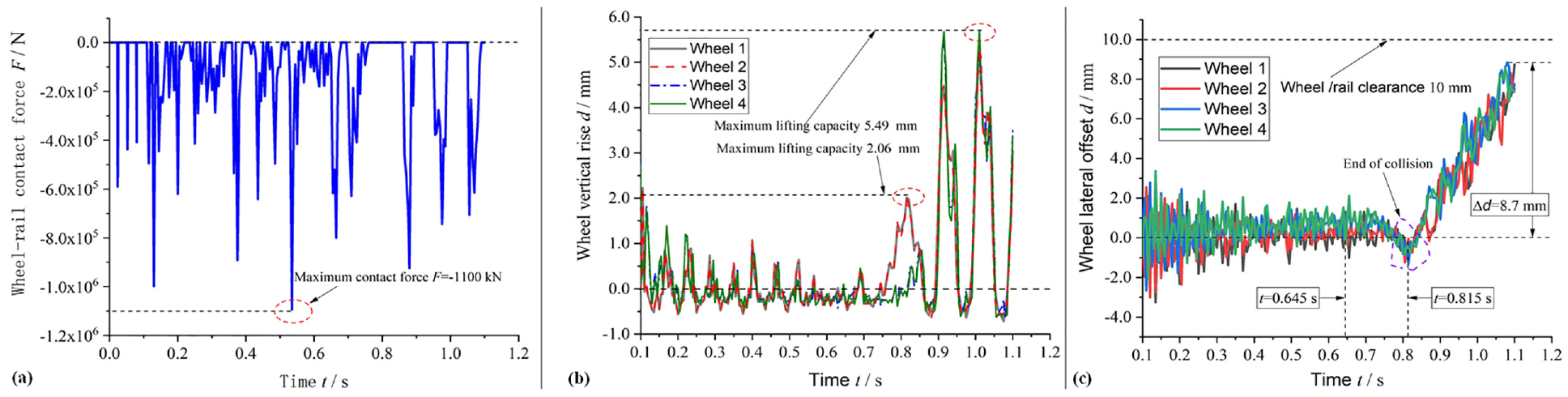
(a) Wheel-rail contact force with time, (b) Wheel vertical rise with time and (c) Wheel lateral offset with time.
Figure 9(a) shows that the test trolley is affected by wheel–rail forces during motion. The vertical contact force reaches a maximum instantaneous peak of 1100 kN. The intermittent rolling wheel contact force suggests that the wheels move in a jumping manner on the rail, rebounding and falling back under the influence of gravity. This highlights the dominant influence of gravity on the wheel–rail contact forces throughout the motion of the test trolley. Figure 9(b) reveals that after 0.1 s, the air spring propels the test trolley, causing it to fall onto the track due to gravity. The vertical lift of the wheelsets fluctuates and gradually decreases due to track excitation. At 0.80 s, a rapid upward trend in vertical lift occurs, caused by reverse forces generated when the driver’s compartment collides with a rigid wall. However, the maximum vertical lift is only 5.49 mm, which is less than the flange height (9.5 mm) of the wheels, and it is also less than 75% (7.125 mm) of the height of the wheels. The vertical lift of the test trolley in the collision process meets the requirements of the EU collision standard EN15227. This indicates that the wheel sets of the test trolley maintain effective contact with the track throughout the collision process. Figure 9(c) shows that with an increasing air spring ejection time, the lateral displacement of the wheelsets gradually shifts to one side, notably after the driver’s compartment impacts the rigid wall, reaching a maximum displacement of 8.7 mm (less than the wheel/rail clearance of 10 mm and the tread width of 45 mm). Before t = 0.645 s, the test trolley wheelsets exhibit approximately symmetric lateral displacement, indicating minimal side shift during operation. Upon reaching the maximum displacement, there is a descent, indicating a successful constraint of the test trolley’s lateral movement by the wheelsets and the track. The collision standard has no specific requirements for the lateral offset of the wheelset, mainly because the lateral offset of the wheelset is limited by the rigid track. Lateral migration is less important than vertical migration. If it is shown that there is controlled energy absorption for the specified vertical offset, the design is generally stable enough for typical lateral offset as well.
The vertical lift and lateral displacement data of the test trolley wheelsets indicate that the test trolley operates normally on the track without derailing during the critical collision period. This demonstrates that the virtual collision test conducted on the driver’s compartment using air spring propulsion complies with non-derailment requirements. Thus, conducting virtual collision tests on the vehicle’s driver’s compartment is feasible and effective.
In the study of vertical lift and lateral offset, the vertical lift is of greater significance in determining whether the vehicle is derailed. When the lateral offset exceeds a gap of 10 mm, the track of the roadbed will form a lateral limit on the vehicle, which plays an important role in ensuring the deviation limit during the vehicle’s ejection process. Therefore, when selecting the parameters of the air spring series parallel combination, it is important to focus on monitoring whether its vertical lift exceeds the height of the vehicle’s wheel flange, which is of great significance for ejection at higher speeds.
Conclusion
In this paper, a method for analyzing the performance of air springs with series-parallel combinations is proposed, and a prediction model for air spring ejection based on this configuration is developed. A virtual collision test platform for air spring ejection is established using finite element numerical simulation, focusing on the driver cab as a case study. The correctness of the air spring ejection performance prediction model is verified through virtual collision analysis, leading to the following conclusions:
(1) The ejection model of air springs is established, and the impact of series-parallel combinations on their ejection performance is analyzed. While adding series-parallel combinations enhances the ejection performance, the increase tends to decrease. This highlights the need for further research to improve the ejection force duration between the air spring and the ejected object to achieve high-performance ejection.
(2) Based on finite element simulation analysis of the driver’s compartment, the correctness of the air spring ejection performance prediction model is demonstrated with only a 9.1% relative error. This validates the applicability of the prediction model for high-speed instantaneous ejection of large-mass rail vehicles utilizing series-parallel combinations of air springs.
(3) The maximum vertical lift and lateral displacement of the test trolley wheels are 5.49 and 9.89 mm, respectively, both of which fall within the limits of the flange height and tread width. This indicates that the virtual collision test does not result in derailment.
(4) By changing the initial pressure, geometric parameters, and series parallel combination of the air spring, different energy levels of ejection can be achieved, which is also beneficial for their integration on different application platforms. Therefore, the application prospects of air springs extend to driving rail vehicles, unmanned aerial vehicles, and air-launched missiles.
This research on the performance prediction of air springs based on series-parallel combinations provides crucial theoretical and technical support for their application in the field of ejection, offering significant practical implications.
Footnotes
Handling Editor: Chenhui Liang
Author contributions
Conceptualization: Yu-Ru Li and Shou-Ne Xiao; Methodology: Yu-Ru Li and Jun-Ke Xie; Investigation: Jun-Ke Xie and Tao Zhu; Writing—original draft preparation: Yu-Ru Li and Shou-Ne Xiao; Writing—review and editing: Yu-Ru Li and Shou-Ne Xiao. All authors have read and agreed to the published version of the manuscript.
Declaration of conflicting interests
The author(s) declared no potential conflicts of interest with respect to the research, authorship, and/or publication of this article.
Funding
The author(s) disclosed receipt of the following financial support for the research, authorship, and/or publication of this article: This research was supported by the National Natural Science Foundation of China (grant numbers 52175123 and 52172409), by Key Technologies R & D Program of Henan Province (grant numbers 232102240092), by Sichuan Outstanding Youth Fund (grant numbers 2022JDJQ002), by the Postdoctoral Foundation of Heilongjiang Province, China (grant numbers LBH-Z23041), and the “14th Five-Year” major science and technology project of CRRC (grant numbers 2022CYY007).
Data Availability
Data will be made available on request.