
Abstract
The double-stator hybrid-excitation vernier motor (DSHEVM) is a type of low-speed high-torque motor. The establishment of an accurate mathematical model of the DSHEVM, accurate determination of the magnetic field distribution, and an explicit physical relationship between the design parameters and the output torque are the keys to multi-objective optimization. This study proposes an accurate DSHEVM subdomain model to obtain precise magnetic field distributions. This subdomain model considers the effects of the relative permeability of the permanent magnets, split-pole slots, and stator slots on magnetic field distribution. The governing equations of the seven subdomains are established in scalar magnetic potential. According to the boundary conditions and corresponding Fourier series expansion at the interface of each subdomain, the magnetic flux density distributions in the main subdomains are obtained, and the output torque of a DSHEVM is analyzed. Based on the finite element method and experiments, the calculation accuracy of the proposed subdomain method is verified. The findings of this study provide a basis for multi-objective optimization and precise analysis of loss and temperature field of the DSHEVM.
Introduction
Motors with low speed and high output torque are widely used in wind power, locomotive traction, marine drives, and other applications. Compared with combinations of motors and gearboxes, low-speed high-torque motors do not experience wear, lubrication, fatigue fracture, or other mechanical gearbox problems, and they have the advantages of a simple structure and low maintenance costs. 1
The most competitive low-speed high-torque motors are magnetically geared motors (MGMs) and permanent-magnet vernier motors (PMVMs). The field-modulated magnetic gear (FMMG) proposed by Atallah and Howe 2 has a novel coaxial magnetic topological structure that surpasses the parallel-axis topology of conventional magnetic gears. Therefore, FMMGs have a high utilization rate of the permanent magnets (PMs), large output torque, and high torque density. The coaxial topology ensures that FMMGs can be readily integrated with motors, that is, MGMs. MGMs have an inherent deceleration function and can replace the combinations of PM synchronous motors and gearboxes. The transmission mechanism, 3 cogging torque, 4 parameter optimization, 5 harmonic analysis of the back electromotive force, 6 and other MGM characteristics have been studied in detail and many results have been reported. Thus, MGM performance characteristics have gradually been optimized. In particular, a pseudo-direct-drive PM machine developed by Atallah has the advantages of high transmission efficiency and a high power factor. 7 However, the complex multirotor structure of MGMs complicates their fabrication. Subsequently, by using a split-tooth structure instead of a stator and ferromagnetic pole pieces, the number of rotors was reduced, and the structure of the MGM was simplified. 8
Because they have only one rotor, PMVMs, in particular the double-stator vernier motor, have the advantages of compact structure and high space utilization, and have become the main area of research in low-speed high-torque direct-drive motors. 9 Adopting Halbach array magnetization 10 or a flux-focusing structure 11 can effectively improve the PM motor output torque. Combining the advantages of PMVMs and MGMs, the inner or outer stator adopts a multitooth split-pole structure, and the double-stator hybrid-excitation vernier motor (DSHEVM) exhibits a higher power factor and higher torque density. 12
The finite element method (FEM) has been widely used in PMVMs, and can provide almost all analysis results, such as the magnetic flux density distribution, torques, losses, and temperature field. However, the FEM is time-consuming, cannot provide the direct physical relationship between the design parameters and performance indicators, and is not convenient for evaluating the initial and optimization designs of PMVMs that require the consideration of different configurations and sizes. To make up for the shortcomings of the FEM in only providing data, the performance optimization of PMVMs based on various optimization algorithms has gradually been deepened. By combining the FEM and genetic algorithm, the output torque can be increased, 13 the torque ripple can be reduced. 14
The analytical method is important in the analysis of the magnetic field and torque characteristics of PMVMs, and it allows the role of harmonics caused by different structures to be analyzed more clearly. In Azeem et al., 15 the air-gap magnetic flux density is expressed as the product of magneto-motive force in the form of a Fourier series and permeance function to obtain a more accurate air-gap flux density; they investigated the detailed contributions of each harmonic component in the production of the back electromotive force and torque. In Yang et al., 16 a double air-gap PM vernier synchronous motor was proposed using a slotted structure of the outer stator, and the torque characteristics were studied by establishing the corresponding general solutions and relevant coefficients of the governing equations of each subdomain. In Zhu et al., 17 considering the slotting effect, an accurate analytical model for the surface PMVM is established by the conformal mapping method, and the slotting effect on the air-gap flux density and torque is analyzed to achieve a power factor computation. In Li et al., 18 the analytical expression of magnetic flux density is given by the magnetic circuit method and modulation function, and electromagnetic torque is discussed.
Compared with the FEM, the calculations of the magnetic field and torque with analytical methods based on the precise subdomain method have faster calculation time and higher calculation accuracy, 19 and provide an analytical basis for the precise calculation of PM loss. The magnetic field distribution and cogging torque of PMVMs are analyzed using the subdomain method, and effects of harmonics on torque, cogging torque, and loss are discussed in detail to improve transmission performance, and efficiency more specifically. 20 The high precision of the subdomain method has been verified using finite element analysis and experimental test methods. 21
For the accurate subdomain method proposed in this study, the governing equations of each subdomain are established, which can reflect the influence of the split-pole slots and stator slots on magnetic flux density. Subsequently, the boundary conditions for each subdomain are determined. By solving Poisson’s and Laplace’s equations, magnetic field density expressions for each subdomain are obtained. The precision of the subdomain method is verified using the FEM and experimental tests, thereby providing a basis for DSHEVM parameter optimization and loss calculation.
DSHEVM transmission mechanism and subdomain model
DSHEVM topology and transmission mechanism
A DSHEVM is primarily composed of two stators and one PM rotor, as shown in Figure 1. There are two air gaps between the two stators and the PM rotor. The split teeth of the inner stator serve as modulators of the air-gap flux density based on the magnetic gearing effect for high torque production, and facilitate ventilation and heat dissipation. The outer stator adopts a conventional convex pole structure, and a relative polar moment angle exists between the inner and outer stators to reduce magnetic leakage and increase the output torque and power factor. 12 The spoke-array structure of the rotor is separated from adjacent PMs by a nonpermeable magnetic material that causes a certain magnetic accumulation effect. PMs in the rotor can be arranged alternately by N and S poles and can also be sinusoidally magnetized for higher output capacity and smaller torque fluctuations.

Geometry of the studied DSHEVM.
High-speed rotating magnetic fields are generated when three-phase alternating currents are connected to the inner and outer stator windings. After modulation by the outer stator teeth and inner split teeth, the harmonic number of the magnetic fields in the inner and outer air gaps is consistent with the number of PM poles on the rotor, and the rotor is driven. Owing to its self-variable speed, the DSHEVM can output a larger torque at a lower speed and is suitable for industrial applications that require low speed, high torque, and compact space.
Accurate DSHEVM subdomain model
In this study, to establish a DSHEVM mathematical model based on the subdomain method, the following assumptions are adopted: (1) The end effects are negligible, (2) permeability of iron is infinite and has zero conductivity, (3) relative recoil permeability of the magnets is
The PMs in the DSHEVM are radially magnetized, and magnetic vector potential formulations are used in two-dimensional (2D) cylindrical coordinates to describe the DSHEVM model. As shown in Figure 2, the entire domain is divided into seven regions: the inner and outer stator slot subdomains (regions 1 and 7), inner stator notch subdomain (region 2), split-pole subdomain (region 3), inner and outer air-gap subdomains (regions 4 and 6), and PM subdomain (region 5).
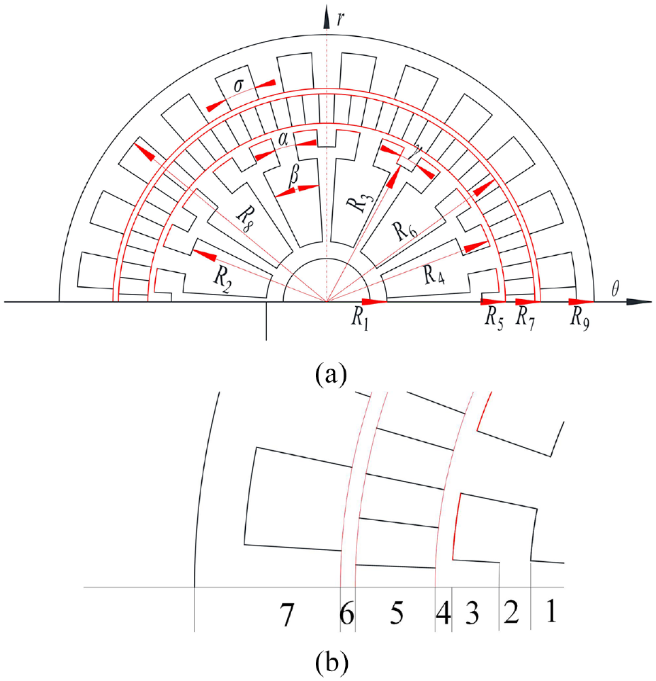
Analytical model of the studied DSHEVM: (a) subdomain model and (b) enlarged view.
The DSHEVM subdomains can be divided into three categories: passive, magnetized, and current-carrying regions. The two air-gap subdomains, the split-pole subdomain, and the inner stator notch subdomain belong to the passive region. The PM subdomain belongs to the magnetized region. The two stator-slot subdomains belong to the current-carrying region. Each subdomain has four regular boundaries.
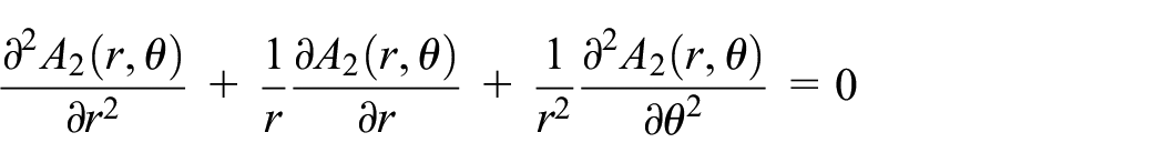
In 2D polar coordinates (r, θ), the radial (Br) and tangential (Bθ) components of the flux density in the air gaps can be expressed as
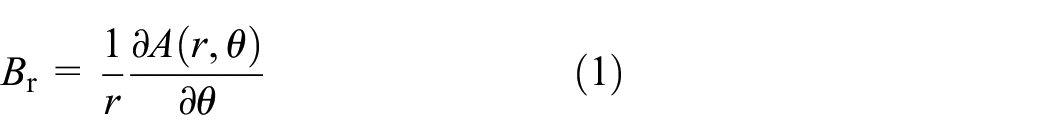
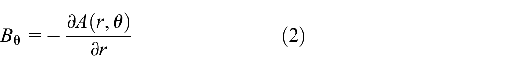
where A is the magnetic vector potential.
According to Ampere’s loop theorem and Gauss’s law, the following expressions can be obtained:


where
Assuming a linear medium, the relationship among the magnetic field intensity

where
Substituting equation (5) into equations (4) and (3) yields

The following formula can be derived with

In the 2D polar coordinates of the DSHEVM model, the magnetic vector potential

where
Analysis of air-gap magnetic field and output torque
The following functions are introduced to facilitate subsequent calculations:
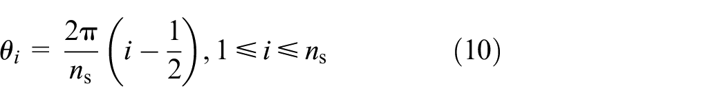
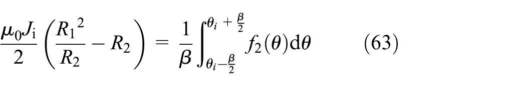
For subdomain 1, that is, the subdomain of the inner stator slot, the horizontal axis in the 2D plane shown in Figure 2 is taken as the initial position. When the width angle of the inner stator slot is β, and there are ns inner stator slots, the central position of the i-th inner stator slot is
Current distributions but no magnetization exist in the inner stator slot.

where J i is the current density of the i-th inner stator slot.
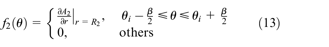
The boundary conditions of the inner stator slot subdomain can be expressed as follows:

where R1 is the inner radius of the inner stator slot (mm) and R2 is the outer radius of the inner stator slot (mm) with
The solution of the Poisson equation shown in equation (11) is partly obtained by the ferromagnetic boundary and partly by the inner stator winding. The general solution of equation (11) can be converted to yield

Equation (14) is the Laplace equation corresponding to equation (11). According to the separation-of-variables method, the magnetic vector potential

Substituting equation (15) into equation (14) yields

where λ is eigenvalue of equation (16).
The solution of equation (16) can be converted into the definite solution of the two ordinary differential equations
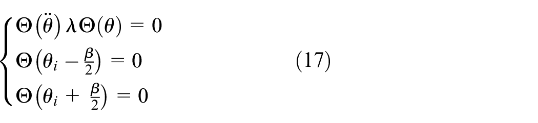

The eigenvalue of equation (17) is


where
The general solution to equation (11) can be obtained by linearly superimposing equations (19) and (20):

The first two terms in equation (21) represent the action of the winding current, and the harmonic term represents the action of the stator boundary. The solution to equation (11) can be expressed as

Equation (22) is a particular solution to equation (11). From equations (21) and (22), the general solution for the inner stator slot subdomain can be determined as

From the boundary condition

Finally, the magnetic vector potential of the inner stator slot subdomain in the DSHEVM can be expressed as
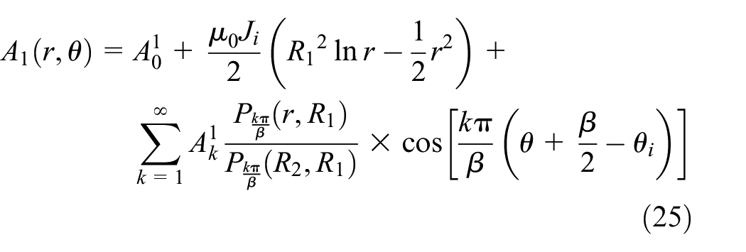
where
Equations (10)–(25) show the calculation process for obtaining the general solution of the subdomain using the separation-of-variables method. This calculation process is followed for the general solutions of all the DSHEVM subdomains, and the subsequent repetitions are not described in detail.
For subdomain 2, that is, the inner stator notch subdomain, the notch width is α, and the center position of the i-th slot opening is defined as

A 2 represents the magnetic vector potential of subdomain 2. The boundary conditions of A2 are expressed in equation (27), and the Laplace equation for subdomain 2 is

where R4 denotes the inner radius of the inner air gap (mm).
for

Similar to the inner stator slot, the inner stator notch lacks windings, and the general solution of subdomain 2 is similar to equation (23). However, the action of the winding current is missing. The general solution of subdomain 2 can be expressed as

According to equation (29), the magnetic vector potential A2 can be expressed as

Where
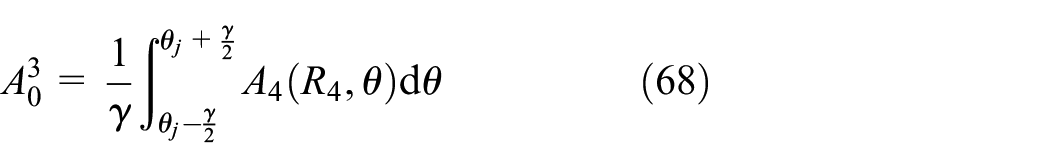
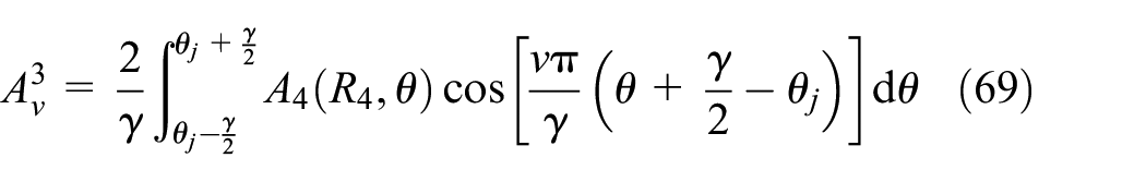
For subdomain 3, that is, the split-poles subdomain, γ is the slot width of the split poles, and the center position of the j-th auxiliary slot is defined as

A
3 is used to represent the magnetic vector potential of the split poles and satisfies the Laplace equation in the domains of inner radius R3 and outer radius R4 delimited by the angles

The boundary conditions of the split-pole subdomain are expressed as

where R3 is inner radius of the split poles (mm).
According to the solution process of subdomain 1, the split-pole subdomain has no effect on the winding current compared with the inner stator slot subdomain. Therefore, the general solution to the Laplace equation for A3 is
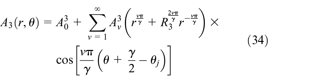
Thus, A3 can be expressed as

where
For subdomain 4, that is, the inner air-gap subdomain, the magnetic vector potential is represented by A4, and the Laplace equation of A4 is given by

where R5 is the outer radius of the inner air gap (mm).
The boundary conditions of the inner air-gap subdomain can be expressed by


There is no electric current in the inner air-gap subdomain, and the general solution can be expressed as

The general solution of the Laplace equation for subdomain 4 can be expressed as

where
For subdomain 5, that is, the PM subdomain, the PMs are radially magnetized, and A5 is used to represent the magnetic vector potential. Considering the magnetization source of the PMs, the Poisson equation for subdomain 5 is

where R6 denotes the inner radius of the outer air gap (mm).
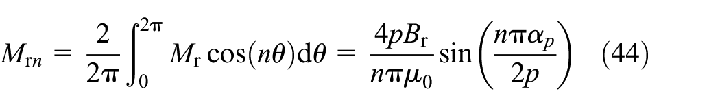
Because north- and south-pole PMs are alternately arranged in a DSHEVM rotor, the radial magnetization in equation (41) in the range of 0–2π can be expressed as

Expanding Mr into Fourier series form yields

which can then be expressed as
The boundary conditions of the PM subdomain are

According to the separation-of-variables method, the general solution for the PM subdomain is


A 5 can be expressed as

where
For subdomain 6, the outer air-gap subdomain, A6 is used to represent the magnetic vector potential. The Laplace equation of A6 can be expressed as

where R7 denotes the outer radius of the outer air gap (mm).
The boundary conditions of the outer air-gap subdomain can be expressed as


According to the separation-of-variables method, the general solution for the outer air-gap subdomain is
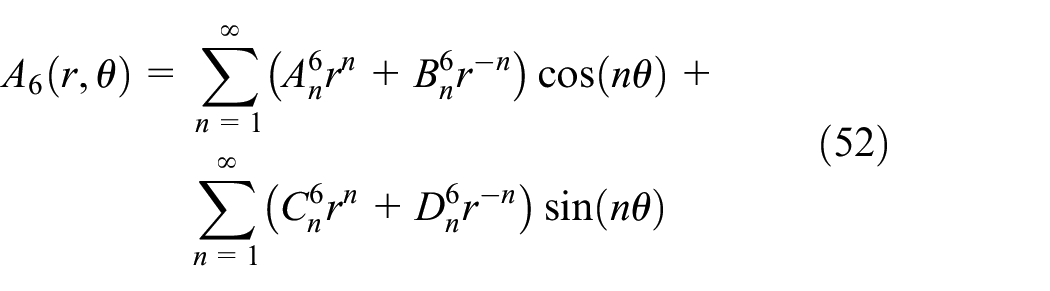
A 6 can be expressed as

where
For subdomain 7, that is, the outer stator slot subdomain, the width of the outer stator slot is σ, and the center position of the z-th outer stator slot is

A 7 represents the magnetic vector potential of the outer stator slot subdomain. Because of the winding current distribution in the outer stator slot, the Poisson equation can be expressed by

where R8 is the outer radius of the outer stator slot (mm) and Jo is the current density of the outer stator slot.
The boundary conditions of the outer stator slot subdomain are

Where R8 is outer radius of the outer stator (mm)
According to the separation-of-variables method and boundary condition
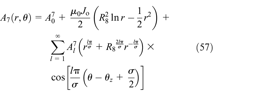
A 7 can be expressed as

where
Integral constants exist in the general solution of the seven subdomains. To solve for the integral constants, two types of boundary conditions, namely, the tangential components of the magnetic potential and the normal components of the magnetic field density at the junction between the seven subdomains, must be considered.
The boundary conditions at r = R2, that is, at the interface between the inner stator slot subdomain and inner stator notch subdomain, can be written as


Substituting the general solutions of subdomains 1 and 2 into equations (59) and (60) yields


The continuity of the radial component of the magnetic field at r = R4 yields the following conditional relation:

Substituting the general solutions of subdomains 2, 3, and 4 into equation (65) yields


The conditional equality can be obtained because of the continuity of the radial component of the magnetic field at the interface between the inner air-gap subdomain and the PM subdomain:

Comprehensively considering the general solution of subdomains 4 and 5 and the conditional equations (72) and (73) yields


At r = R6, namely, the boundary between the PM subdomain and the outer air-gap subdomain:

The coefficients


At the junction between subdomains 6 and 7, the following conditional equality holds:


Substituting the general solutions of subdomains 6 and 7 into equations (84) and (85) yields


First-order multivariate equations can be constructed when a Fourier series expansion is performed on equations (61)–(64), (66)–(71), (74)–(77), (80)–(83), and (86)–(89). By solving the multivariate equations, the Fourier series coefficient and the magnetic flux density distribution function of each subdomain can be obtained.
The electromagnetic output torque is obtained using Maxwell’s stress tensors. 14 A circle of a radius within the inner and outer air-gap subdomains was considered as the integration path, and the output torque on the rotor consists of the sum of the torque by the outer stator and inner stator, and is expressed as

where L is the effective length of the motor air gap (mm).
Analysis of magnetic field distribution and cogging torque
The parameters of the DSHEVM model are listed in Table 1. A three-dimensional finite element model of the DSHEVM was established using ANSYS software, and its magnetic flux density distribution and output torque were calculated.
Parameters of the DSHEVM model.

Magnetic flux density distribution in inner and outer subdomains
Using both the FEM and subdomain method, the magnetic flux densities in the middle of the inner and outer air gaps and split poles are obtained, as shown in Figure 3.
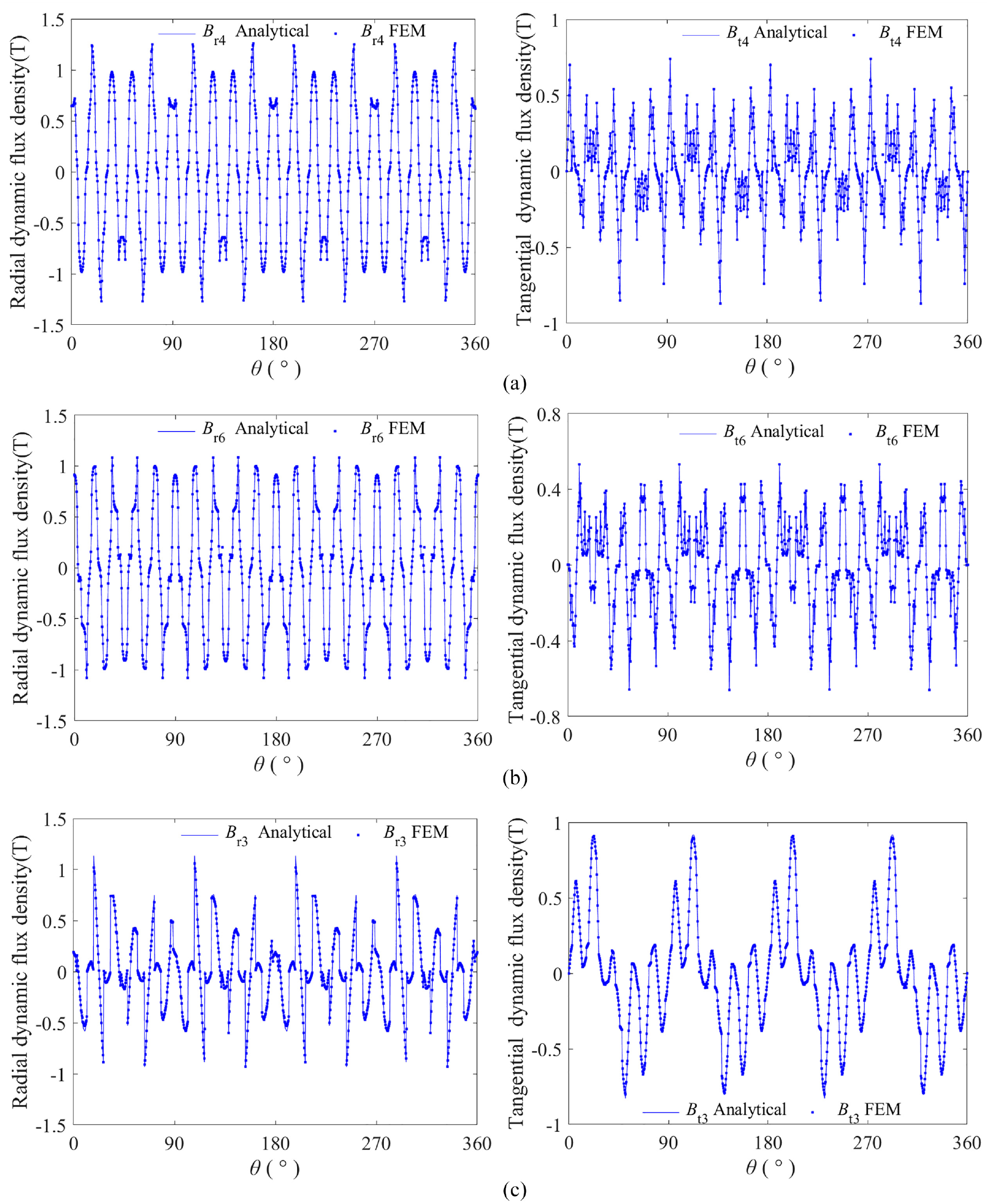
Magnetic flux density distribution in the partial subdomains by subdomain method and FEM: (a) inner air gap, (b) outer air gap, and (c) split poles.
Figure 3 shows that the magnetic field distributions of the DSHEVM based on the subdomain method are consistent with those of the FEM simulation. In the range of 360°, that is, the entire magnetic field, there are 20 main waveforms, which is consistent with the number of PM poles on the rotor. Therefore, equal-pole coupling and motion output of the PMs on the rotor can be realized. Meanwhile, the useless harmonics in the tangential magnetic flux density increased significantly, and the amplitudes of the tangential magnetic flux density are significantly smaller than those of the radial magnetic flux density. According to the Maxwell stress tensor method, the tangential magnetic flux density in the middle of the inner and outer air gaps can be further improved by structural optimization, and the harmonic components can be optimized to increase the maximum output torque.
The fluctuation ranges and laws of the magnetic flux densities obtained using the FEM and subdomain method are highly consistent and have high precision. For example, the radial and tangential magnetic flux densities in the middle of the inner air gap calculated using the FEM ranged from −1.2762 to 1.2603 T and from −0.8693 to 0.7433 T, whereas the ranges of the analytical solutions were from −1.2706 to 1.258 T and from −0.8704 to 0.7395 T, respectively. The errors are minimal.
DSHEVM dynamic torque
The dynamic and cogging torques on the rotor of the DSHEVM were plotted using the subdomain method and FEM simulations, as shown in Figures 4 and 5, respectively.

Dynamic torque curves of DSHEVM.

Cogging torque of DSHEVM.
Figure 4 indicates that the output torque of the DSHEVM obtained by the subdomain method is consistent with the results obtained by the FEM; however, the output torque obtained by the subdomain method is slightly smaller. The average output torque values obtained by the FEM and the subdomain method are 127.9521 and 127.7541 N m, respectively. The maximum and minimum values of the output torque obtained by the FEM and the subdomain method are 129.1831 and 126.2832 N m, and 128.8122 and 126.0135 N m, respectively.
From Figure 5, the fluctuation amplitude of cogging torque of DSHEVM is approximately 1.24 N m. The results of the subdomain method and FEM are highly consistent. The subdomain method can be used to describe the dynamic torque characteristics of DSHEVM with high precision.
DSHEVM torque test
The DSHEVM prototype with example parameters in Table 1 is shown in Figure 6. A torque test platform was established using a loading machine, controller, and other components. The dynamic output torque and cogging torque of the DSHEVM prototype are shown in Figures 7 and 8, respectively.

Torque test platform of example DSHEVM prototype.

Output torque of the DSHEVM prototype.

Cogging torque of the DSHEVM prototype.
Figure 7 shows that the average output torque of the DSHEVM prototype is 121.0429 N m, smaller than that obtained by the subdomain method. As shown in Figure 8, the cogging torque of the prototype is much larger than the calculated value, and the fluctuation amplitude is 5.12 N m, much larger than the 1.24 N m calculated by the subdomain method. In the torque test, the fluctuation frequency of the output torque is more complicated because the processing and assembly errors of the prototype makes the air gap uneven, and the air-gap thickness is slightly larger than the design value. However, the main frequency and fluctuation laws of dynamic torque and cogging torque are consistent with the FEM results.
Although there are some errors between the experimental and simulation results of DSHEVM torque, this is mainly reflected in the output torque mean value and fluctuation amplitude, which is mainly caused by the machining error of the DSHEVM prototype. However, the fluctuation laws of the output torque and cogging torque are consistent with the FEM results. The FEM results are highly consistent with those of the subdomain method. Therefore, the subdomain method can be considered to have higher precision and can be used as the basic form of structure optimization for DSHEVMs.
Conclusion
This study proposed a precise subdomain method to predict the flux density distribution and torque of a DSHEVM. The method fully considers the influences of the slot effect of the split-tooth design and the special structure of the PM rotor on a complex magnetic field, and reflects the effects of the relative permeability of the PMs, slot height, and modulation tooth height on the magnetic field distribution. The corresponding analytical expressions lay the foundation for analyzing the influence of the electromagnetic parameters on the output torque. Through an example analysis of the magnetic field distribution of a DSHEVM using the subdomain method and FEM simulation and by conducting a comparison analysis of the output torque obtained via the subdomain method, FEM simulation, and prototype experiment, it is concluded that the subdomain method has high calculation accuracy and can be easily combined with various optimization algorithms to achieve multi-objective optimization.
Footnotes
Appendix
Handling Editor: Sharmili Pandian
Author contributions
Xiuhong Hao: Research ideas and writing – original draft. Xiang Cai: Experimental, writing – review & editing. Yujing Nie; Formula derivation and finite element simulation.
Declaration of conflicting interests
The author(s) declared no potential conflicts of interest with respect to the research, authorship, and/or publication of this article.
Funding
The author(s) disclosed receipt of the following financial support for the research, authorship, and/or publication of this article: This work was funded by the Science Research Project of the Hebei Education Department (ZD2022090), S&T Program of Hebei (236Z1902G), and Hebei Natural Science Foundation (E2022203090).