
Abstract
A small rock shotcrete robot is applied in the deep tunnel dynamic disaster physical simulation system in order to simulate the final operation process of the tunnel project. The robot’s spraying operation and control include many kind of factors. In this paper, the main parameters affecting the spraying operation are analyzed by establishing the spraying model and coating growth model. For matching reasonably the spraying parameters, the matching equation of spraying quality and spraying gun parameter model and spraying feed speed has been derived. Based on the matching equation, the spraying gun structure and robot control system are designed, and the spraying distance and spraying gun movement velocity including horizontal and vertical driving have been controlled better. On the basis of theoretical analysis, a small rock hole shotcrete robot prototype has been developed and the spraying experiments have been finished. The experimental results showed that the model and equation established can guided the spraying quality control. With the increase of the injection elevation angle, the length of the long and short axes of the elliptic coating becomes larger, and the average thickness of the coating center is between 2.23 and 2.34 mm, which meets the design index of the injection robot. The rock hole shotcrete robot meet the design requirements.
Introduction
During the excavation and maintenance of tunnels and roadways, due to the complexity of geological conditions, dynamic disasters such as rock burst have become the key safety problems restricting the safe construction of deep roadways, 1 as show in Figure 1.

Rock burst disaster diagram.
Shotcrete-bolt support technology is one of the more widely used support technologies which can effectively improve the strength and stiffness of tunnel surrounding rock and ensure the safety and stability of tunnel projects in tunnel construction. The main functions of shotcrete-bolt support are as follows: the coating on the inner wall of the tunnel can be able to improve the tensile strength and shear stress of the tunnel surface and reduce the situation of plastic shear slip or plastic flow; In order to minimize the possibility and harm of rock burst, in addition to taking active preventive measures, it is usually necessary to have strong construction technical support to ensure construction safety. 2 The common support method is to spray steel fiber or plastic fiber concrete onto the arch and side wall immediately after sandblasting, and then add anchor bolts and steel mesh. If necessary, steel arches can be erected and advanced bolts placed for support. Therefore, shotcrete is an essential part in the construction process of rock tunnel engineering. The quality of shotcrete determines the safety of tunnel construction.
The research on shotgun-type robots has a history of more than 30 years since the 1990s. Fan et al. paid a lot of effort in the early stage of the research on shotgun-type robots, and produced more achievements in the structural design, 3 kinematic analysis, 4 and control system design of shotgun-type robots, 5 which laid the research foundation for subsequent researchers. On this basis, the subsequent researchers developed a planning algorithm for the sprinkler head of the spraying robot, which greatly improved the spraying effect of the robot.
The AI-based shotcrete robot jointly developed by the Civil Engineering Department of National Central University and the Civil Engineering Department of National Chenggong University has great advantages in defect repair and automation. And the experimental demonstration has also proved its defect modification ability and proved the feasibility of its technology. 6 It can be seen that the robot has certain advantages in repairing wall cracks, but it is aimed at an ordinary wall, its surface is flat, and the spray robot is generally applied to the pipe inside, the robot is still incomplete in this respect.
The University of Cambridge and the University of Bath have jointly developed a robot that can automatically spray ribbed concrete shells. 7 The robot has a deep study on the material deposition process of complex templates, and the addition of vision system and trajectory tracking algorithm gives the robot more possibilities in processing and manufacturing. However, in terms of engineering applications, the robot can not guarantee that it can reasonably repair the loopholes of the pipeline, and the machine is relatively large, which can not be used in narrow pipeline robots have great limitations.
Technische Universität Braunschweig studied a 3D print-based shotcrete robot that used FPR material as reinforcement material in concrete additive manufacturing, and then sprayed concrete. 8 The advantage of the robot is that it can make more shapes of concrete walls, and it will be more reliable in terms of achieving patching walls. However, its cost will be more expensive, and the application will be more inclined to building materials, and the scope of use in engineering applications is relatively narrow.
Moniz and Costelha of Polytechnic Institute of Leiria proposed an algorithm for the shotcrete path in railway tunnels. 9 The algorithm of path generation and execution realized the automation of robot shotcrete projection. This method can be used in larger tunnels, but it has not been actually used in engineering development, and no prototype can verify the feasibility of its algorithm, so it has certain defects.
Wu et al. proposed a method to solve the inverse kinematics in the position domain of redundant manipulators by combining T-IK and parameterization.10,11 The proposed method is applied to an eight-DOF tunnel jet robot, and the performance of the robot proves that the improved algorithm is more effective. However, due to the large number of joints in the robot, there will be many problems in the multi-task situation. To sum up, there are a lot of effective researches on nozzle path planning and intelligent algorithm of the international shotcrete robots. However, the object of these studies is the working scene with small curvature or even plane, and there is less research on the shotcrete robot in the pipeline. At the same time, most of the study of the spray model is complicated to establish, and can not be used in the pipeline.
Wang et al. 12 improved the installation structure to improve the stability and reliability of the speed encoder in order to solve the problem of frequent damage of the speed encoder of the gunite robot, and established the optimal mathematical model of the gear transmission system to improve the efficiency and design volume of the gear transmission. Aiming at the environmental problems of spraying operation, Xu et al. 13 proposed adaptive sensing recognition and wheel diameter planning strategies for shotcrete robots under multiple working conditions. Li et al. 14 designed a crawler-type shotcrete robot to meet the needs of tunnel shotcrete support in coal mines, which can implement wet shotcrete process and has a high degree of automation. Qin et al. 15 established the linear force balance equation between the joints of the gunite robot, and carried out simulation analysis, but there was no experimental analysis, and the reliability needs to be verified. Xie et al.16,17 developed an eight-DOF gunite robot arm, and used LiDAR to model the tunnel surface in 3D, realizing the identification of the surface to be sprayed through 3D point cloud data. By optimizing Gmapping algorithm, Han et al. improved the environment mapping ability of the tunnel gunite robot. 18 Gao et al. 19 aiming at the problem of controlling the roadway position and attitude of the spray gun of the spray robot, used the inclination sensor to measure the angle of the driving mechanical joint in real time, and finally completed the spray action. Wrock and Nokleby20,21 have completed the measurement of the thickness of the sprayed concrete based on the registration method of the benchmark mark, and proposed an approach to generating a set of via points for use in manipulator trajectory path planning in 2020.The University of Ontario Institute of Technology has designed an end effector system for shotcrete robots that enables autonomous shotcrete and surface radiation measurements. 22 Luo et al. 23 simplified the complex mechanical arm structure model into a simple planar two-link manipulator model, solving the inverse kinematics problem of shotcrete manipulators. Yang et al. 24 proposed a robust LiDAR SLAM method for detecting and compensating degraded scenes, and experimental results show that the proposed method has better robustness than LeGO-LOAM and LIO-SAM.
In addition, Cheng and Deng 25 from Shenyang University of Technology applied the model predictive control algorithm to carry out trajectory planning and tracking control for a gunite robot in a coal mine roadway, and its work was stable and stable. Wang of Chongqing Research Institute China Coal Science and Technology Group, 26 applied Workbench module to topological optimization of the arm fixed base of the gunite robot, which reduced its total weight by 30%; Yuan 27 Anhui University of Science and Technology, applied D* algorithm to carry out path planning for gunite robots, so that the gunite robots can carry out path planning in unfamiliar environments or scenes with dynamic obstacles.
Tang’s research team has developed a full-section loading device and a drilling robot28,29 The use scenario of the gunite robot is in a relatively narrow pipeline, which solves the international shortage of small gunite machines. In addition, the spray model is simple to establish, the control method is classical and reliable, so it is widely used. At the same time, the spraying experiment of the machine proves that the machine can better realize the spraying operation.
In the second section of this paper, the structure design of the gunspray robot, the three-dimensional model of the gunspray structure and the ANSYS stress analysis graph are discussed. In the third section, the growth model and spraying model of shotcrete coating are established, and the rationality of the robot is verified theoretically. The fourth section describes the establishment of the control system of the robot and the detailed application of fuzzy PID control in the robot. The fifth section verifies that the robot meets the test requirements by spraying the robot at different angles. The sixth section is the summary of the full text and the prospect of the future.
Overall design of the shotcrete robot
Because the application scene of shotcrete robot is in the hole with small diameter, the structure of shotcrete robot has certain limitations. Because of the large size of the active walking structure, the shotcrete robot in this paper needs to drag the mud pipe to walk, and the driving force required by the robot will also increase. Therefore, the active walking structure is not suitable for the shotcrete robot in this paper. Therefore, this paper uses a worm gear to drive the jet robot forward and the motor to drive the worm rotation. Since the motor is installed outside the tunnel, the large motor is selected as the driving source, which does not lack installation space, but also can bring enough torque to make the jet robot move stably in the tunnel. The walking mechanism design model is shown in Figure 2.

Main view of spindle and feed mechanism. 1 – shaft sleeve, 2 – support table, 3 – flange, 4 – end cover, 5 – spindle, 6 – screw base, 7 – slide table, 8 – fixed frame, 9 – mud pipe, 10 – coupling, 11 – gas pipe, 12 – translation motor.
In the overall structure of the shotcrete robot, the nozzle is the key to slurry atomization. The nozzle has two main functions, one is to atomize the mud, and the other is to stabilize the flow of fluid inside the nozzle. The nozzle structure of the shotcrete robot is mainly divided into mechanical nozzle and pneumatic nozzle. 30 Compared with the mechanical nozzle, the pneumatic nozzle has a large flow adjustment range, and can control the size of the droplets by adjusting the ratio of gas to liquid, so as to achieve a better atomization effect. Moreover, the applicable liquid types are wide and the nozzle structure is simple, so the pneumatic atomizing nozzle is selected in this paper. To meet the technical specifications, the spray elevation angle can be changed from 0° to 150°, and the nozzle length can be changed within 5 mm.
According to the working conditions and technical indicators of the spraying equipment in the simulation system, the overall structure of the shotcrete robot is shown in Figure 3. The spraying equipment is mainly composed of four parts: the spraying gun mechanism, the rotating mechanism, the variable diameter support mechanism, and the traveling mechanism, which can complete the spraying function and accurately control the circumferential rotation function, adapt to the diameter of the pipeline and provide stable support for spraying work, as well as the function of the end effector to directly enter and exit the simulated tunnel in a straight line.

Shotcrete robot.
In the tunnel excavation simulation system, the shotcrete robot sprays atomized cement slurry jet from the nozzle during spraying work, and at the same time, it generates a reaction force on the spraying gun mechanism, 31 and the direction of the reaction force is opposite to the direction of the jet. 13 The reaction force borne by the nozzle can be calculated by equation (1).

In equation (1), q is the effective flux in the nozzle flow passage, which is 33.3 L/min, and p is the nominal pressure of stainless steel bellows, which is 1.6 MPa.
Excessive reaction force will cause serious deformation of the stressed parts, resulting in the equipment can not work normally, so it is necessary to carry out static analysis of the spray gun mechanism in the environment of Ansys Workbench. During the finite element analysis, the influence of damping on the system is ignored, the structure that does not affect the stiffness and strength of the gun mechanism is removed, and the structure is appropriately simplified and reasonable constraints are applied. In this way, the solving efficiency can be improved and the calculation time can be saved. The simplified model is shown in Figure 4.

Simplified model of gun mechanism.
The material requirements of the workpiece of the spray gun mechanism are easy to process, good corrosion resistance, good wear resistance, light weight, good mechanical properties, and economy. In this paper, 6061 aluminum alloy is selected as the material for processing parts. The bellows in the spray gun mechanism are purchased parts, and their material is 304 stainless steel, which has the advantages of good processing performance, high toughness, and corrosion resistance. The injection elevation angle of the shotcrete robot can be adjusted between 90° and 150°, and the direction of the reaction force borne by the nozzle changes with the change of the injection elevation angle. Figure 5 shows the static analysis of the force when the injection elevation angle is 120°.
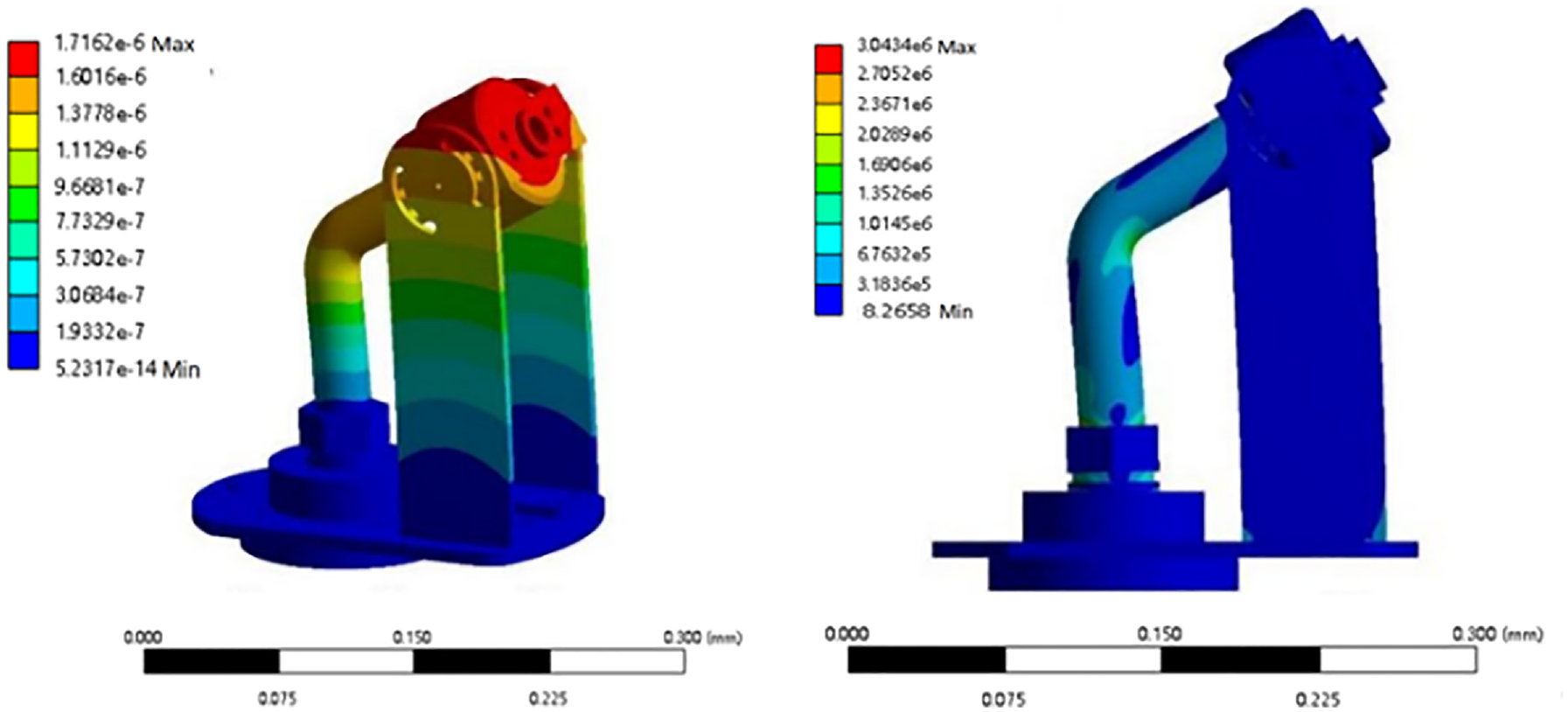
Static analysis of the spray gun mechanism.
Through the stress diagram of the spray gun mechanism, it can be seen that the connection position of each part and the bend of the sheet metal parts bear large stress, and the analysis result is less than the allowable stress value of the material, which meets the requirements of use.
The force distribution of parts subjected to reaction forces at different injection elevation angles is shown in Figure 6. The maximum deformation position on the polyline appears in the range of 90°–95°, and the maximum deformation value is about 0.003 mm, so the deformation influence can be ignored, and the design of the spray gun mechanism meets the design requirements.

Force of parts under different injection elevation angles.
Spray and growth models
The most important thing for the shotcrete robot is to ensure the coating quality 32 of the tunnel surface, and the uniform coating is the key requirement to ensure the quality of the coating. There are many factors that affect the uniformity of the coating, including the injection elevation angle, the flow rate of the coating, the moving speed of the spray gun, the height of the spray gun from the spraying surface, and the spacing 28 between the spray gun motion trajectories. Due to the fixed flow rate of spraying object and coating, it is assumed that the spraying volume of the shotcrete robot is uniform and there is no slurry loss in the spraying process. Based on this assumption, the spray model and growth model of the spray gun during the working process of the shotcrete robot are established.
Spray model
Firstly, consider the parameters that affect the spraying, when the spray gun is spraying, the atomized paint sprayed by the nozzle produces a cone-like external flow field in the space, and the fog cone angle θ is constant. When the spray gun is sprayed vertically on the surface of the work piece, a circular coating with a radius of r will be produced on the surface of the work piece and the spraying will be uniform, as shown in Figure 7(a). Considering that the spray gun is not completely perpendicular to the surface to be worked in the actual work, the elevation angle α and the vertical height h of the spray gun are introduced without loss of generality, as shown in Figure 7(b).

Spray model: (a) the spray model on the plane and (b) the spray model on the curved surface.
According to the analysis of the spraying characteristics of the shotcrete robot, it can be known that the spraying area of the rock hole by the shotcrete robot can be approximately transformed into a curved surface, which is formed by the intersection of a conical surface and a cylindrical surface. The curved surface equation can be obtained by solving the two equations simultaneously. Because the conical surface equation can not be directly obtained, so we can get the rotation equation by rotating a curve around a fixed line. Take the vertical drop point from the spray point of the nozzle to the horizontal line as the origin of the 3D coordinates, let α be the elevation angle of the nozzle, θ be the injection angle of the nozzle, and let the centerline of the conical surface formed by the nozzle to be a straight line L, so the direction vector of the straight line L can be obtained as shown in equation (2).

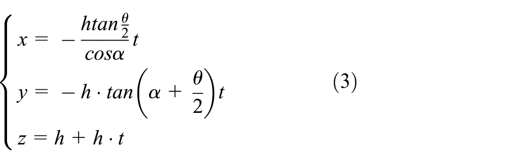
The rotation curve T can be obtained from the coordinate points of the nozzle and the intersection point of the spray cone and the hypothetical XOY surface as equation (3)
Let the coordinate of the nozzle be

Equation (4) is combined with equation (3) of rotation curve T, and equation (5) of curved surface of rotation can be obtained by eliminating

And because the equation for the cylinder is as follows:

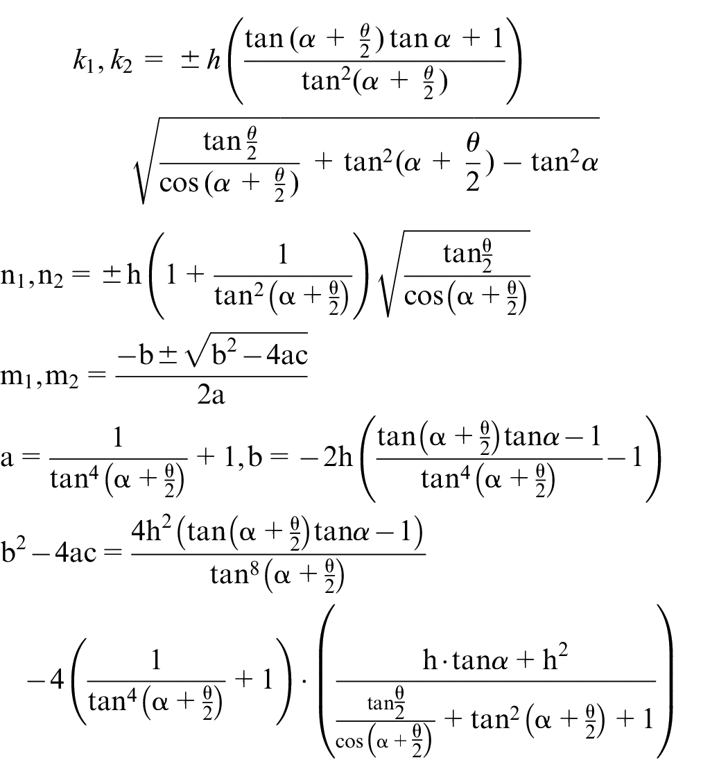
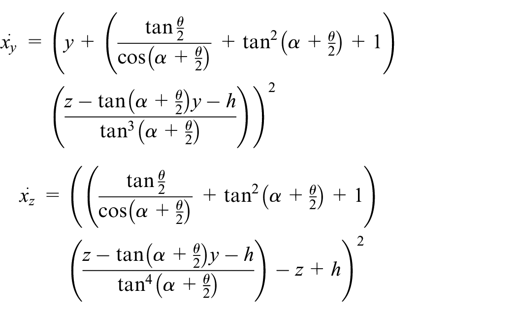
Therefore, the equation of intersecting surfaces can be obtained by combining equations (5) and (6). According to the rotation curved surface equation and the intersecting curved surface equation, equation (7) can be obtained by dividing them into two parts.

Where:
Growth model
Suppose that the density of the slurry in the spraying volume is certain in the process of spraying, and the mass density formula can be used to obtain the
This model makes the following assumptions about the actual physical phenomena of the pneumatic nozzle of the spraying equipment:
(1) The fluid in the nozzle is regarded as an incompressible liquid at room temperature; (2) The interaction force between particles in the flow field is ignored; (3) Ignoring the surface tension of the fluid in the flow field; (4) Ignoring the potential energy difference between the nozzle inlet and outlet; (5) The flow field is isothermal, ignoring energy exchange; (6) The influence of mass force is ignored. The growth model of mud is equation (8).

Among them:
Simulation and analysis of nozzle flow field
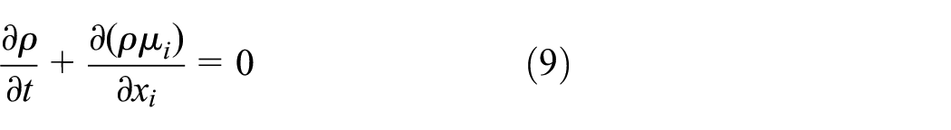
The nozzle of the shotcrete robot involves the mixed fluid of gas and liquid in the working process, so the VOF method is used to simulate the flow process of the inner and outer flow fields in the model calculation domain, and the influence of the spray gun parameters on the spraying performance is studied 33 . The continuity equation is as follows:
The N-S equation is as follows:

Where, ρ is fluid density; u i is the projection of velocity vector in i direction; X i is the coordinate position of the fluid in i direction; μ is the dynamic viscosity coefficient; p is fluid pressure; f i is the volume force of the fluid in i direction. The spray calculation is carried out by using the Realizable k-ε model, 30 and the turbulent kinetic energy k and its dissipation rate ε equation in the Realizable k-ε model are as follows:
Where:
The fluid inside the nozzle of the spray equipment is set, the mixed fluid is gas-liquid two-phase flow, the cement slurry is set as the main phase, the air is set as the second phase, and the cement slurry parameters are self-defined, the density of the cement slurry is set to, ρ1 = 2050 kg/m3 the viscosity is set to, μ = 0.46 Pa s and the gravitational acceleration is set to 9.8 m/s 2 . Set the boundary conditions, since the cement slurry is an incompressible fluid, the speed inlet is preferred, and the inlet speed is set to 5.85 m/s; Since air is a compressible gas, the inlet boundary condition preferentially selects the pressure inlet, and the inlet pressure is set to 0.3 atm; The outlet boundary condition is also set to the pressure outlet, and the outlet pressure is set to 0.1 atm (one standard atmospheric pressure); The outflow field wall boundary is set to a fixed wall and a slip-free boundary. Set to the Time Step Size to 1 × 10⁻⁴, the Number Time Step to 100 steps, and the Max Iterations to 200 to obtain a residual change plot, as shown in the Figure 8.

Residual change plot.
The simulation data obtained after solving were passed through the post-processor, and the internal and external flow field changes of the nozzle during spraying were analyzed according to the processed image and statistical data. Figure 9 shows the velocity cloud at the outlet of the external flow field when the injection elevation angle is 90°.

The plot at the exit of the outflow field: (a) velocity cloud plot and (b) XY scatter plot.
By observing the velocity cloud image at the outlet of the external flow field, it can be found that when the mixed fluid ejected from the nozzle moves to the outlet plane, a circular coating is formed on the plane, the velocity in this region is evenly distributed, and the velocity gradually decreases from the center to the edge. The velocity distribution in this region is consistent with the model distribution of the coating thickness.
Control method of spraying equipment
Most concrete spraying robots use intelligent algorithms to control the trajectory of the robot. Although such control methods have a high degree of automation, their algorithms are also highly likely to be affected in practical engineering. Since the working track of the concrete spraying robot studied in this paper is only a straight line, it only needs to control the rotation of its nozzle, and there is no need for complex algorithms. The classical fuzzy PID method is selected to control the robot comprehensively.
The control system of the shotcrete robot in the tunnel driving simulation system is composed of switching power supply, STM32 single chip microcomputer, touch screen, encoder, servo driver, DC servo motor and PC end, and the control system built is shown in Figure 10. The motion parameters of the shotcrete robot are set by the upper computer, and the control signal is transmitted to the single chip computer through USB. The single chip computer controls the mud spraying machine and the stepper motor according to the received control signal. The sensor is installed on the stepper motor, and as a feedback element, the speed parameter of the stepper motor is fed back to the MCU. The MCU processes the information returned by the sensor, and compares it with the actual output value. According to the comparison result, the current speed of the motor is determined, and the rotation speed of the stepper motor is compensated, and the precise control of the speed of the stepper motor is finally realized. A limit switch is added to the front end and end of the shotcrete robot to prevent the horizontal movement of the shotcrete robot from exceeding the motion range and damaging the motor.

Control system: (a) block diagram of control system and (b) control box of electric control system.
The digital PID algorithm is divided into position type, incremental type, and speed type. Position type PID is characterized by the proportion of the input is the difference between the target value and the actual value. The output of position type PID algorithm can not be directly connected unless the digital control valve is used, otherwise it needs to pass the interface circuit. The advantages of incremental PID algorithm include that the impact of machine failure is small, the amount of computation is small, but the cumulative error is relatively large, and it is often used in the control of stepper motor. At the same time, the output of incremental PID algorithm can be converted into analog quantity through the accumulation mechanism with zero-order holding characteristics such as stepper motor. Incremental PID control algorithm is the most widely used. The position PID has integral saturation phenomenon, but the incremental PID and the speed type do not have integral saturation, even if the deviation exists for a long time, each output is limited, will not exceed the upper and lower limits, and the actuator can not reach the limit position. So the incremental PID algorithm is chosen. But in many actual operations, the controlled object is easily affected by load changes and external loads, resulting in changes in the characteristic parameters of the object, then the conventional classical PID control cannot meet the requirements. In order to improve this problem, fuzzy PID control system is used, 34 which system block diagram is shown in Figure 11.

Block diagram of fuzzy PID control system.
According to the control rule experience in the existing literature, the set fuzzy rule table is as follows (Tables 1–3):
Δkp Fuzzy rule table.

Δki Fuzzy rule table.

Δkd Fuzzy rule table.

There are many methods to solve ambiguity in fuzzy PID control. After comprehensive comparison, this paper adopts gravity center method to solve ambiguity, and its expression is as follows:

Among:
z
0– The exact value of the output after deblurring; z
i
– Numerical values in the field of fuzziness;
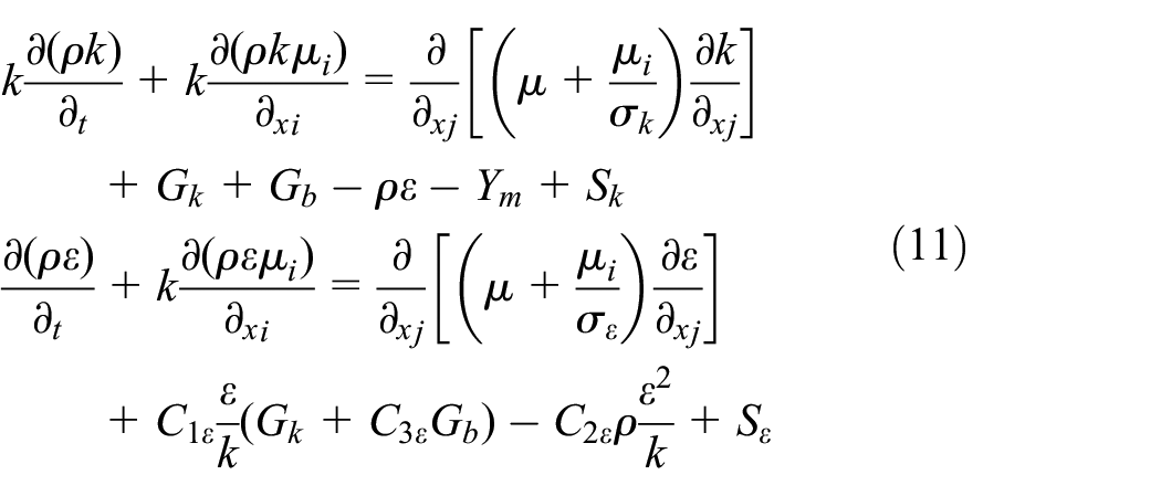
The simulation design diagram of conventional and fuzzy PID under the same interference is as follows (Figure 12):
Simulation design drawing of conventional and fuzzy PID.
In fact, the adaptive fuzzy PID based on fuzzy control algorithm uses fuzzy algorithm to tune the three parameters kp, ki, kd of ordinary PID. In the process of fuzzy adaptive PID parameter tuning, the fuzzy rules between kp, ki, kd parameters and the deviation e and the deviation change rate ec are set firstly. The deviation e and the deviation change rate ec are obtained by comparing loop and closed-loop feedback. Then, e and ec are used as the input of the fuzzy controller, and the changes Δkp, Δki, and Δkd of kp, ki, and kd are determined according to the fuzzy rules that have been set. Then the three parameters of the PID controller are adjusted adaptively. Finally, the three parameters of the optimal performance of PID controller are optimized, so that the control system has good dynamic performance and stability.
It can be seen from the curve of Figure 13 that compared with PID parameters obtained by fuzzy algorithm, the system output response speed is accelerated, the results converge, and the oscillation is reduced.

PID and Fuzzy PID output response curve: (a) PID output response curve and (b) Fuzzy PID output response curve.
Experimental study of spraying equipment
In order to verify the parameter analysis of the spray gun and the theoretical calculation results of the nozzle flow field simulation, a suitable experimental environment is established, and the experimental related equipment model is shown in Figure 14. Through this experimental platform, the influence of the spray gun mechanism’s injection elevation angle change and the spray length change on the coating quality can be analyzed.

Experimental equipment model.
Spray experiment of spray elevation angle
The distance between the rotation center of the spray gun mechanism and the gauze mesh was 100 mm, the flow rate of cement slurry was 2 m3/h, the atomization pressure was 0.3 MPa, and the spray elevation angle of the nozzle in the spray mechanism was 90° and 120°, respectively, as shown in Figure 15. After the spraying experiment, the gauze was removed to obtain the corresponding coating when the injection elevation angle was 90° and 120°, as shown in Figure 16. Table 4 was obtained after the data were summarized.

Spraying experiment: (a) 90° elevation and (b) 120° elevation.

Shape of the coating: (a) mud coating at 90° and (b) mud coating at 120°.
Coating parameters at different spray elevation angles.

According to Table 4, it can be seen that:
(1) With the increase of the injection elevation angle, the length of the major axis and the minor axis of the oval-like coating formed by spraying becomes larger.
(2) The average thickness of the center of the oval-like coating formed by spraying is between 2.23 and 2.34 mm, which meets the design indicators of the shotcrete robot.
Spraying experiment of nozzle length change
The injection elevation angle of the nozzle in the shotcrete robot is 150°, the distance between the rotation center of the spray gun mechanism and the gauzing mesh is 100 mm, the flow rate of cement slurry is 2 m3/h, the atomization pressure is set to 0.1 MPa, and the extended lengths of the nozzle are 1, 2, 3, and 4 mm respectively for the experiment.
The analysis shows that with the increase of the elevation angle of the nozzle, the length of the long axis and short axis of the oval-like coating formed by spraying increases, and the average thickness decreases, which is consistent with the theoretical analysis conclusion of the coating model, as shown in Table 5.
Coating parameters for different nozzle lengths.

Spraying experiment of spraying speed
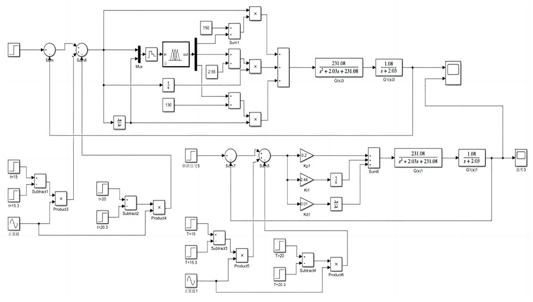
The theoretical and measured values in Table 4 were corrected by adjusting the extended lengths of the nozzle. The theoretical value of the long axis of the coating was taken as the target of the measured values. After many tests, the coating parameters of different injection elevation angles with the smallest deviation between the theoretical value of the short axis of the coating and the measured value were obtained. According to the measured values of the modified coating parameters, the rotation speed of the spraying equipment was set as 20°/s, c = 97.25% × a, and the spraying speed was calculated. The spraying speed corresponding to different elevation angles of the spraying equipment under actual conditions was obtained, as shown in Table 6.
Spraying travel speed corresponding to different elevation angles.
Similarly, when the spraying elevation angle of the spraying equipment is certain and different rotation speeds are set, the matching speed of the spraying travel speed can be calculated in the same way to ensure the coating quality and achieve the shotcrete support function for the tunnel.
Conclusions
On the basis of comparative analysis of the research contents of shotcrete robot, and according to the working condition requirements and technical indicators of spraying equipment, the structural design of spraying equipment is completed. Then through the mechanical simulation analysis of the key mechanism of the shotcrete equipment, it is verified that the relevant mechanism can meet the design and working condition requirements. In addition, this paper innovatively established the coating model, and based on the spray gun structure and coating distribution model, obtained the coating thickness growth relationship of shotcrete robot. The internal and external fields of the nozzle are simulated by the simulation analysis software. The results are consistent with the conclusions of the spray gun mathematical model about the coating thickness distribution and the influence of the elevation Angle of the spraying equipment on the coating, which verifies the correctness of the mathematical model. Through the simulation analysis, it is found that the inlet air pressure and the elevation Angle of the sprayer can control the air pressure, reduce the distance between the nozzle and the sprayed surface or reduce the rotational speed. The control method in this paper adopts fuzzy PID control algorithm to control the speed of the feed motor. Compared with the basic PID control algorithm, the response speed of the control motor is improved, and the feed positioning accuracy of the jet robot is improved. In addition, the model established in this paper is an ideal state based on assumptions, but in fact, these influencing factors will be more complex in real problems, and can not be generalized. Therefore, in the future, researchers will improve the model and introduce some parameters to make the model more applicable.
In this paper, the spraying model and growth model of the spraying robot are constructed with a unique model construction method, and the spraying model of the spraying robot is explained reasonably from the Angle of mathematical model. In addition, the fuzzy PID control method adopted in this paper can better control the gunite robot and is more cost-effective. In this paper, the robot is tested at different angles in the actual working environment, and the excellent performance of the robot is demonstrated.
The application scope of the shotcrete robot in this paper is mainly for the spraying of rock cracks in the tunnel, which can effectively improve the strength of the inner wall of the tunnel and reduce the incidence of rock burst, which can not only produce social benefits, but also improve the safety of tunnel construction personnel and reduce the probability of tunnel accidents, which is of great significance to the whole society.
The growth model and spraying model in this paper are only set up under ideal conditions, and the viscosity and density inside the mud are not considered more. In addition, although the fuzzy PID method is suitable for this model, it is still unknown whether many new algorithms match this robot. Therefore, in the future, this robot should continue to improve and modify this model on the premise of fully considering the characteristics of mud, and then continue to modify and improve this robot on the premise of adapting to the new algorithm, so that the robot in this paper can have more diverse and accurate functions.
Footnotes
Handling Editor: Chenhui Liang
Author Contributions
This article presents a portion of QiangLiu’s mas-ter thesis, which was supervised by Liquan Li and assist supervised by Zhonglin Zhang. All authors made substantial contributions to the conception or design of the work, the analysis and interpretation of the data, and the draft of the manuscript.
Declaration of conflicting interests
The author(s) declared no potential conflicts of interest with respect to the research, authorship, and/or publication of this article.
Funding
The author(s) disclosed receipt of the following financial support for the research, authorship, and/or publication of this article: Funding for this research has been provided by grants from the National Science Foundation of China—Physical simulation test system of deep tunnel / tunnel dynamic disaster (NO.51427803).