
Abstract
The efficient utilization of energy stands as a paramount priority on the international stage. Currently, there are various issues associated with the multi-power source couplers in automobiles. Addressing concerns related to the large size, poor reliability, low durability, and inefficient energy conversion of these couplers, a novel Permanent Magnet Synchronous Mechatronic-Electro-Hydraulic Coupler (MEHC) has been proposed. This system integrates a traditional permanent magnet synchronous machine with a swash plate axial piston pump/motor, enabling the mutual conversion of electrical, mechanical, and hydraulic energy. This paper primarily investigates the losses and efficiency of MEHC in both pure electric motor mode and electro-hydraulic coupling mode. Compared to our group’s previous Induction Asynchronous Mechatronic-Electro-Hydraulic Coupler (IA-MEHC), MEHC demonstrates lower losses and higher torque. Additionally, the paper also computes the electrical power external characteristics and comprehensive power external characteristics of the MEHC in pure electric motor mode. In the calculations within this paper, electric power is the primary power source, and in the electro-hydraulic coupling mode, hydraulics only provide auxiliary assistance. The research outlined in this paper lays a robust groundwork for future advancements and innovations in MEHC technology. With the capacity to bolster its performance, efficiency, and reliability, this groundwork holds the promise of accelerating the rapid development and widespread adoption of MEHC in automotive applications.
Keywords
Introduction
To tackle environmental concerns, bolster energy security, drive technological innovation, and respond to consumer demands, governments worldwide are proactively enacting policies and regulations to stimulate the advancement of new energy vehicles.1,2 These measures contribute to alleviating environmental pressures and achieving climate change mitigation objectives.3,4 The development of modern electric vehicles not only needs to adapt to complex working environments but also requires a high driving range. Therefore, improving the energy efficiency of electric vehicles is a pivotal aspect in the development of electric vehicles. 5 Sun et al. 6 proposed a system-level design optimization method based on the actual operating environment. Multi-objective optimization based on sequential subspace optimization and climbing algorithm was proposed in Jin et al. 7 and Sun et al. 8 These studies mainly focus on comprehensive optimization of motor efficiency and electromagnetic performance using different multi-objective optimization methods. Diao et al. 9 and Sun et al. 10 conducts an extensive literature review on design optimization techniques for SRMs and introduces a novel scheme utilizing high-frequency signal injection with an iterative strategy to extract rotor position angles in interior permanent magnet synchronous motors. Today, besides pure electric vehicles (EVs), there are also hybrid electric vehicles (HEVs) and fuel cell vehicles (FCVs). However, each type of new energy vehicle has its own advantages and disadvantages. HEVs combine electric motors with internal combustion engines, which can increase driving range but do not completely eliminate the use of fossil fuels and increase system complexity. FCVs have higher fuel cell costs, which add to operating costs. 11 Hydraulic power energy storage systems are favored due to their high-power density, rapid energy conversion, and other advantages. 12 This technology, when applied in new energy vehicles, addresses issues such as the short driving range of pure electric vehicles, low energy recovery efficiency, and frequent charge-discharge cycles that accelerate battery aging while meeting the power requirements of vehicles. 13 Therefore, our team has introduced an innovative Permanent Magnet Synchronous Mechatronic-Electro-Hydraulic Coupler (MEHC). This system integrates electrical and hydraulic forces to facilitate energy conversion among diverse power sources, speed regulation, and seamless power transmission. These features are all geared toward maximizing energy efficiency. 14 This technology is capable of converting electrical energy into hydraulic energy through the MEHC and storing it in a hydraulic accumulator to provide the necessary power for the vehicle during conditions such as vehicle start-up or acceleration. This technology can also reduce peak torque when the vehicle starts, providing good protection for the battery. This is a groundbreaking new design that is expected to bring significant improvements to the development and innovation of new energy vehicles, enhancing performance and reliability, reducing environmental impact, and promoting the widespread use of new energy vehicles. 15
MEHC offers several advantages compared to traditional power coupling, including efficient energy conversion, high power density, energy recovery, reliability, and versatility, making it crucial for addressing modern engineering and energy challenges. 16 Therefore, our research group has undertaken numerous efforts in the field of MEHC, including enhancing energy management strategies, optimizing structural parameters, and reducing noise and vibration. Li et al. 17 proposed a novel electromechanical-hydraulic power coupling system for electric vehicles, established a rule-based dynamic energy management strategy, and confirmed the feasibility and superiority of the new model. Additionally, they eliminated speed instability during the electromechanical-hydraulic power transition process by adjusting the inclination angle of secondary components. Ultimately, the verification results illustrate that the battery power consumption is reduced by 14.7%, and the energy recovery rate of the accumulator is as high as 94.3%. Wang et al. 18 made improvements to the mechanical-electric-hydraulic power coupler proposed by our research group. They introduced a new asynchronous mechanical-electric-hydraulic power coupler (IA-MEHPC). The electrical structure parameters of the IA-MEHPC were optimized using an approximate response surface-based optimization method. Simulation results showed that, compared to the pre-optimized structure, the peak motor torque of the optimized IA-MEHPC increased by 5.78%, and the torque pulsation coefficient reduced by 15.83%, aligning with engineering expectations. Liu et al. 19 To improve the MEHC’s noise, vibration, and harshness performance, an electromagnetic vibration and noise simulation analysis was performed with a six-pole 36-slot motor as the research object. The research results were imported into the harmonic acoustics module for a noise simulation analysis, and two different-shaped magnetic isolation bridge optimization schemes were proposed. The results suggested that both optimization solutions could effectively reduce motor vibration and noise. Scheme one reduced the maximum noise by about 6.5% and scheme two by 10.4%. In the current research field of MEHC, our team has accumulated a substantial body of valuable research outcomes. However, despite these accomplishments yielding profound insights and understanding across various aspects, we have not yet to extensively present the research on analyzing the external characteristics of MEHC. Research into the external characteristics of electric power determines the transmission efficiency, energy consumption, and precision of power output of MEHC in actual mechanical systems, which profoundly affects its performance and reliability.
Given the exceptional performance and distinctive features exhibited by MEHC, our research team hypothesizes that it may hold potential for driving vehicles. Therefore, we have undertaken several efforts, including practical on-vehicle experiments with the coupler, establishing mathematical models, and conducting simulation analyses. Yang et al. 20 proposed a novel mechatronics-electro-hydraulic power coupling system (MEH-PCS) to reduce the high peak torque during frequent stops and starts and improve the dynamic performance of the vehicle. They established a rule-based active optimal energy management strategy to control real-time energy distribution and the dynamic switching of working modes. By comparing it with AMESim-certified pure electric vehicles, the feasibility and superiority of the MEH-PCEV were confirmed. Verification results indicated a reduction of 14.418% and 21.174% in the battery consumption rate for the MEH-PCEV in the new European driving cycle and the American city cycle, respectively. Jia et al. 21 proposed a master-slave type hybrid electric-hydraulic power vehicle (MSEH-HEV). They designed a rule-based control strategy for energy allocation and mode switching. A joint simulation of the MSEH-HEV was conducted using AMESim and Simulink, and a comparison was made with an electric vehicle authorized by AMESim to validate the superiority of the MSEH-HEV. The simulation results show that in the Economic Commission for Europe (ECE) and the Extra Urban Driving Cycle (EUDC), the MSEH-HEV has a 15% reduction in battery consumption, and the motor peak torque is significantly reduced. Chen et al. 22 proposed a hybrid electric-hydraulic vehicle and several operating conditions during the vehicle’s motion. Using the state of charge (SOC) of the battery as a constraint, orthogonal experimental matrices for the electric-hydraulic ratio and speed thresholds under various operating conditions were established based on the Taguchi method. Through simulation, the multiple parameters’ effects on motor torque and hydraulic torque, as well as SOC and their proportional influence, were evaluated. The simulation consequences show that the motor torque and hydraulic torque are reduced, and thus, the vehicle’s acceleration performance and energy recovery efficiency are improved. Zhang et al. 23 researched a novel electric-hydraulic hybrid electric vehicle (EHHEV) that features various operating modes and multiple energy sources. They established a rule-based control strategy and verified the superiority of EHHEV in energy management through steady-state simulations. Furthermore, they combined Q-learning with deep neural networks to create a double deep Q-network (DDQN)-guided EMS. Experimental results indicate that the EMS significantly improves vehicle fuel efficiency. The energy management strategy has confirmed the exceptional performance of the vehicles in optimizing energy utilization and maximizing their range. This lays a solid foundation for the future widespread application and development of these vehicles, which are brimming with prospects and potential. 24 However, whether in motor or vehicle research, external characteristics studies directly impact vehicle performance, efficiency, safety, and range capabilities.
Based on the deficiencies identified in the studies mentioned above, this paper primarily investigates the external electric power characteristics of MEHC, intending to gain a deeper understanding of its responses and performance in various modes, thus addressing the gaps in our research. The content of this paper holds typical foresight and offers significant inspiration and guidance for future research and experimental work, providing valuable experience and reference for further studies.
The specific research in this paper is as follows:
(1) Equations for copper loss, iron loss, mechanical loss, torque, and efficiency in the MEHC are provided.
(2) In the realm of this paper, we improved Bertotti’s proposed iron loss separation calculation model. We harnessed Ansys Maxwell software for stator magnetic density simulation, as well as losses simulation in the stator, rotor, and permanent magnets.
(3) Comparisons between the new MEHC and our previous versions regarding losses and torque were carried out.
(4) The losses and efficiency of the MEHC in both pure electric motor mode and electro-hydraulic coupling mode were comprehensively analyzed.
(5) This paper calculates the external characteristics of electric power and comprehensive power external characteristics of the MEHC in pure electric motor mode.
Structure, principles, and applications
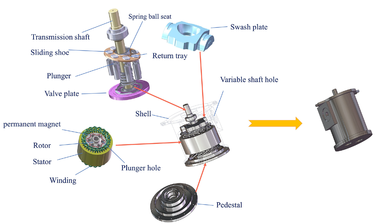
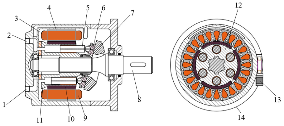
Figures 1 and 2 illustrates the structure and operation principle of the MEHC. 1 – Low-pressure oil outlet; 2 – High-pressure oil outlet; 3 – Cooling circuit; 4 – Stator core; 5 – Plunger; 6 – Shoe; 7 – Swash plate; 8 – Transmission shaft; 9 – Windings; 10 – Permanent magnet; 11 – Rotor core; 12 – Cylinder block; 13vSwash plate tilt control system; and 14 – Housing. The overall structure of the MEHC consists of a permanent magnet synchronous motor, a swash plate axial piston pump/motor, a base, an inclined disk, and an outer casing. The swash plate axial piston pump/motor is the primary component of the inclined-axis hydraulic assembly. At the same time, the permanent magnet synchronous motor serves as the primary component for converting electrical energy. The rotor of the permanent magnet synchronous motor is equipped with piston holes, into which we insert the pistons of the piston pump. The pistons are secured to the incline using shoes, and these shoes articulate with the piston heads, allowing them to rotate freely within the shoes. The pistons rotate and execute reciprocating motion within the piston holes, responsible for hydraulic functions. We can precisely control the fluid flow by adjusting the swash plate angle. The central rotating shaft in the structure transfers mechanical energy to various components, and these components work together to achieve the conversion of electrical power, mechanical energy, and hydraulic energy.
Structure schematic diagram of MEHC.
MEHC structure schematic.
IA-MEHPC has a structure similar to MEHC, with the only difference being the type of motor used. MEHC employs a permanent magnet synchronous motor, while IA-MEHPC utilizes a three-phase asynchronous motor.
The energy conversion process of MEHC is as follows, covering multiple key steps, from electrical energy to mechanical power and then to hydraulic energy, fully showcasing the outstanding capability of the MEHC in multifunctional power source conversion.
Mutual Conversion of Mechanical and Hydraulic Energy: (1) The mechanical energy is converted into hydraulic energy. Mechanical energy acts on the transmission shaft, driving the cylinder to rotate. The plunger follows the cylinder in its rotational movement and, in conjunction with components such as the slipper and swash plate, undergoes reciprocating linear motion. In the plunger chamber of the inlet side, the plunger moves outward in the chamber, gradually increasing the chamber’s volume until it enters the outlet chamber area. This phase is the oil suction process. In the plunger chamber of the outlet side, the plunger moves inward, continuously reducing the chamber volume, increasing the pressure inside the chamber, and delivering high-pressure oil. This phase is the oil pressure phase. (2) The hydraulic energy is converted into mechanical energy. High-pressure oil enters the plunger chamber from the inlet chamber. The plunger moves outward, driving the cylinder to rotate with the cooperation of the swash plate. The rotation of the cylinder further drives the transmission shaft to rotate, outputting mechanical energy externally. In the outlet region of the plunger chamber, the plunger moves inward, decreasing the volume of the plunger chamber, and discharging low-pressure oil.
Under two different operating conditions, with each rotation, the cylinder completes a cycle of energy conversion. The inclination angle of the swash plate can be adjusted according to the requirements of the operating conditions to increase or decrease the output of mechanical energy or hydraulic energy.
Mutual Conversion of Electrical and Mechanical Energy: (1) When electrical energy is converted into mechanical energy. By inputting three-phase alternating current through the conductors, a rotating magnetic field is generated in the stator slots through the interaction between the three-phase windings in the stator and the stator core. This rotating magnetic field drives the rotor to rotate and the transmission shaft to move, thereby achieving the external output of mechanical energy. (2) When mechanical energy is converted into electrical energy. Mechanical energy drives the rotation of the rotor embedded with permanent magnets via the transmission shaft. The rotating magnetic field of the permanent magnets cuts across the three-phase windings in the stator slots, generating alternating electromotive force, which is then output externally as current through the conductors.
In various operational modes of automobiles, the electric power system plays a critical role. Therefore, the efficiency of the electric power system has the most significant impact on the overall performance of the MEHC. The external characteristics of an electric motor refer to the performance attributes of the motor system under different conditions, including factors such as torque, power, efficiency, and losses. Typically, the primary focus is on the relationship between the motor’s output torque and speed. The output power of the electric power system is influenced by the losses generated by the motor during operation, with greater losses resulting in lower electric power output. The losses in the electric power system primarily include iron losses, copper losses, and mechanical friction losses.
Research on electric power and integrated power is crucial for the design, performance optimization, and applications of MEHC. 25 An in-depth study of these two aspects can enhance the efficiency, reliability, and versatility of MEHC, thereby meeting the requirements of various engineering and industrial applications.
The electrical power balance equation is as follows:

where Pin represents the motor’s input power. Pout is the motor’s output power. PFe stands for core losses. Pcu denotes winding copper losses. Ppm represents permanent magnet eddy current losses. Pw signifies windage losses. Pf is bearing friction losses.
When the motor operates under a load condition, the efficiency calculation equation is as follows:

where ω represents the motor rotor angular velocity. T e represents the motor’s output torque and the calculation equation is as follows:

The equation for calculating the displacement V of the hydraulic portion of MEHC is as follows:

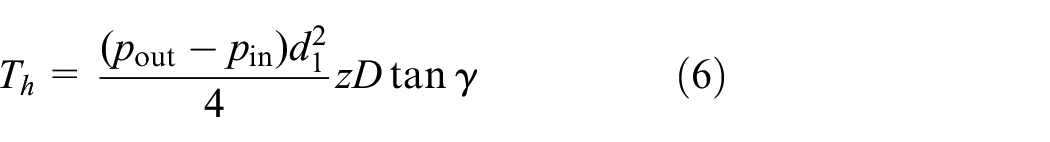
where A represents the piston’s bottom area. d1 is the piston diameter. z is the number of pistons. D is the circular pitch diameter of the pistons. s is the displacement from the piston’s lower stop position to the upper stop position. γ is the incline angle of the incline.
When hydraulic energy is converted into mechanical energy, the theoretical output torque of MEHC is given by:
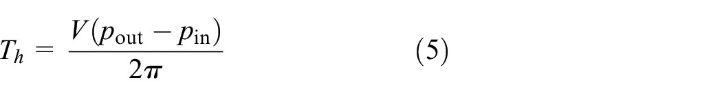
where pout represents the outlet oil pressure and pin represents the inlet oil pressure.
When equation (4) is substituted into equation (5), the theoretical equation for calculating the output torque is as follows:
When hydraulic power and electric power are both involved in operation, the output torque of MEHC is:

where Th represents the hydraulic power output torque. Te represents the electric power output torque.
The MEHC output power is:

where Ph represents hydraulic power output and Pe represents electrical power output.
The comprehensive efficiency of MEHC is:

where ηh represents hydraulic power efficiency. ηe represents electrical power efficiency. Phin is hydraulic power input efficiency. Pein is electrical power input efficiency.
In the research process, based on design and operational principles analysis, we have tentatively established the parameter settings and material choices, as shown in Tables 1 and 2.
MEHC motor structural parameters.

Definition of structural materials.

The multifaceted energy conversion characteristics of MEHC provide it with the capability to extend into multiple domains, meeting the requirements of various operating conditions. Its diverse applicability expands its prospects for use in various fields, including but not limited to transportation, energy, industrial, and environmental sectors. Our team has proposed a new Mechanical-Electric-Hydraulic Dynamic Coupling Drive System (MEH-DCDS) based on MEHC, with a structure as shown in Figure 3.

Schematic of MEH-DCDS principles.
The structure of the MEH-DCDS power transmission system is shown in Figure 3. It mainly consists of the hydraulic control unit, brake master cylinder, vehicle control unit, power battery pack, power converter, high and low-pressure accumulators, and MEHC. MEHC is the core component of the entire power transmission system, capable of converting mechanical, hydraulic, and electrical power interchangeably. The power battery is the sole power source for the entire vehicle, and the hydraulic energy in the high-pressure accumulator comes from regenerative braking or is converted from electrical energy.
Below are descriptions of the different operating modes of the MEHC-powered vehicle.
Initial Power Mode: When the vehicle starts, there is a momentary demand for high power. Hydraulic fluid from the high-pressure accumulator enters the low-pressure accumulator, driving the vehicle to reach the desired speed through hydraulic power. Electric power comes into play only when hydraulic power is insufficient.
Boosted Power Mode: After reaching a speed threshold, the power battery begins to supply power, and the vehicle enters acceleration mode. Both electric and hydraulic power work concurrently, with torque being combined in the MEHC, propelling the vehicle at higher speeds.
Constant Speed Cruise Mode: As speed increases and reaches a certain threshold, hydraulic power is turned off, and the vehicle enters a constant-speed driving phase, with only electric power driving the vehicle, operating in its high-efficiency range.
Power Regeneration Mode: When the vehicle is idling, electric power is converted into hydraulic power, pumping hydraulic fluid from the low-pressure accumulator into the high-pressure accumulator, efficiently recharging the accumulator to its optimal threshold.
Brake Regeneration Mode: During braking, when at high speeds, the coupler operates as a generator, converting energy into electrical power stored in the power battery. At low speeds, the coupler operates as a hydraulic pump, converting kinetic energy into hydraulic energy stored in the high-pressure accumulator. In the case of strong braking, both electric and hydraulic power participate in braking, converting a portion of the braking energy into electrical energy stored in the power battery. In the case of emergency braking, mechanical brakes are engaged, with the ABS taking over.
Loss calculation
MEHC is an efficient energy conversion device in which iron loss and permanent magnet eddy current loss are the primary factors affecting performance and efficiency, in addition to copper loss and mechanical loss. 26 The following text will provide a detailed analysis with a focus on these primary losses to optimize the design and application of MEHC.
Copper loss and mechanical loss
Copper loss
The skin effect leads to an increase in the winding resistance and an increase in losses. 27 MEHC armature windings use copper conductors with smaller cross-sectional areas, and the internal current distribution within the winding is uniform, minimizing the impact of the skin effect on copper losses. If we neglect the skin effect, the equation for calculating the armature winding copper losses is as follows:

where Pcu represents armature winding loss. m is the number of phases in the motor. I is the effective phase current of the armature winding. R is the phase resistance of the armature winding.
When the motor is operating, the working temperature changes due to the generation of winding losses. Therefore, to accurately calculate the copper losses in the winding, it is necessary to consider the effect of temperature changes on the resistance of the copper conductors in the winding. When the temperature is t, the equation for calculating the resistance of the armature winding is as follows:

where Rt is the resistance of the armature winding at temperature t. Ra is the resistance of the armature winding when the motor starts operating. αa is the temperature coefficient of the armature winding resistance at the start of motor operation. For copper, α ≈ 0.004°C−1. ta is the temperature at the start of motor operation.
The equation for calculating Ra is:

where K′F represents the resistance increase factor when considering the skin effect. When not considering the skin effect, K′F = 1. ρw is the resistivity of the winding conductor at the start of motor operation. N is the number of turns in series per phase of the armature winding. lo represents the average half-turn length of the winding coil. Ao1 is the cross-sectional area of the winding conductor. a1 is the number of parallel branches per phase of the winding.
Mechanical loss
The mechanical losses in MEHC electric power primarily include windage losses and bearing friction losses. 28 The magnitude of windage losses depends primarily on factors such as the motor’s structure, the design of the fan blades, and the air resistance of the ventilation system. The magnitude of bearing friction losses depends on factors such as pressure on the friction surfaces, friction coefficients, the smoothness of the friction surfaces, and the type of lubricating oil and its operating temperature. Therefore, calculating the mechanical losses of the motor can be quite challenging. In most cases, loss estimation is based on existing motor experimental data.
Mechanical losses in the motor:
Windage losses
The equation for calculating windage losses is:

Where a the roughness of the rotor’s surface in contact with the gas. Cf is the air friction coefficient. ρ0 is the gas density in the motor’s operating environment. ωm is the rotor’s angular velocity. r is the rotor’s radius. L is the rotor’s axial length.
The equation for calculating the friction coefficient Cf is:

where Reδ is the radial Reynolds number. Rea is the tangential Reynolds number. The equations for calculating these Reynolds numbers are:

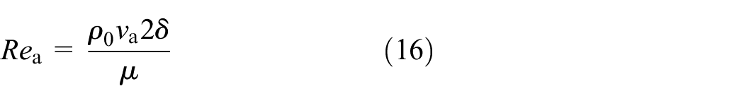
where δ is the air gap length. μ is the relative magnetic permeability of the rotor’s silicon steel material. va is the viscosity coefficient of the gas in the motor’s operating environment.
Shaft friction loss
The equation for calculating rolling bearing friction loss is:

where F is the speed load of the bearing. d is the diameter at the center of the rolling element. v is the circumferential speed at the center of the rolling element.
Iron core loss
Iron core hysteresis loss
The mechanism of iron core loss: In electric power systems, the stator and rotor are made of stacked silicon steel laminations. Silicon steel is a ferromagnetic material with many tiny magnetic domains inside. The magnetic flux density generated in the windings induces an electromotive force (EMF) in these domains, which requires power to overcome the induced EMF and results in corresponding losses. 29
The hysteresis loop of a ferromagnetic material is depicted in the Figure 4.

Hysteresis loop of iron core material.
The energy consumed in one magnetization cycle per unit volume of iron core is:


where Ph is the hysteresis loss density in the iron core. T is the change period of the magnetic field in the iron core. B is the magnetic flux density in the iron core. H is the magnetic field strength in the iron core. Pah is the alternating hysteresis loss generated within the iron core. Prh is the rotational hysteresis loss generated within the iron core. Both hysteresis losses depend on the magnetic field frequency and the amplitude of magnetic flux density.
The equation for calculating hysteresis loss per unit volume is:

where Kh is the hysteresis loss coefficient. Bm is the amplitude of the magnetic flux density in the iron core. f is the frequency of the magnetic field variation. α is the hysteresis loss calculation parameter, typically α = 2.
Iron core eddy current loss
When the frequency and amplitude of the magnetic field remain constant, higher magnetic permeability and electrical conductivity, as well as thicker laminations, can lead to increased stator core eddy current losses. 30
When the stator and rotor iron cores are exposed to a sinusoidal alternating magnetic field, according to the basic principles of electromagnetic fields, the equation for calculating the eddy current loss per unit mass of the stator iron core is:
where ρ is the resistivity of the stator and rotor iron core material. ρFe is the density of the stator and rotor iron core material. ΔFe is the thickness of the silicon steel lamination. Bm is the amplitude of the magnetic flux density. f is the frequency of the magnetic field variation.
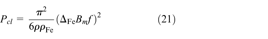
For a given thickness of silicon steel laminations, the equation for calculating eddy current losses is:

where Kcl is the eddy current loss coefficient, and its expression is:

Anomalous core loss
Initially, when calculating the core loss of a motor, most scholars, both domestically and internationally, believed that core loss primarily consists of hysteresis loss and eddy current loss. 31 However, a significant amount of experimental results indicates that the sum of hysteresis loss and eddy current loss does not exactly match the total core loss but is slightly smaller than the total loss. Therefore, some researchers refer to the difference between the total loss and the sum of hysteresis loss and eddy current loss as anomalous loss. The equation for calculating anomalous loss when ferromagnetic materials are subjected to sinusoidal alternating magnetic fields is as follows:

where Pex represents an anomalous loss. Kex is the anomalous loss coefficient. Bm is the amplitude of the magnetic flux density. f is the frequency of the magnetic field variation.
Eddy current loss in permanent magnets
Eddy current losses also exist in permanent magnets, but compared to eddy current losses, hysteresis losses in permanent magnets are much smaller and can be neglected in the calculation process. While eddy current losses in permanent magnets may be relatively small, MEHC employs an embedded permanent magnet synchronous motor, and the thermal dissipation conditions for the permanent magnets are not ideal. Even small eddy current losses can cause an increase in the temperature of the permanent magnets, leading to an increase in rotor losse. 32 Furthermore, when permanent magnets operate in a high-temperature environment, they are prone to demagnetization, which can affect the motor’s service life and efficiency.
Permanent magnets are thin conductors, and their shape and size are shown in Figure 5.

Permanent magnet.
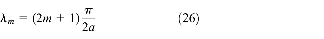
The equation for calculating eddy current losses in permanent magnets is:

where a is half the width of the permanent magnet. b is half the length of the permanent magnet. d is half the thickness of the permanent magnet. δ is the skin dept. J is the current density in the permanent magnet. H is the magnetic field strength in the permanent magnet. σ is the electrical conductivity of the permanent magnet. m is the number of terms in the series solution. λm, γ, βm, βmr, and βmi are coefficients determined by δ and m.
Where:


When the skin depth is much greater than a and b, equation (25) can be simplified to:
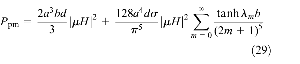
where μ is the magnetic permeability of the permanent magnet.
When the skin depth is much smaller than a and b, equation (25) can be simplified to:

When the skin effect in the permanent magnet is significant, eddy current losses can be simplified as being dependent on the eddy current density along the total edge length of the permanent magnet.
To analyze the magnetic field in MEHC electric motors, it is necessary to derive the relationship between magnetic induction B and the armature current and the permanent magnet. To do this, a vector magnetic potential A with spatial coordinate functions is introduced. The magnetic induction B and vector magnetic potential A satisfy the following relationship:

Taking into account the magnetomotive force of the permanent magnet and the armature current, the electromagnetic field equations are:

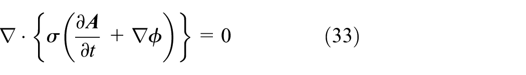

where φ is the scalar magnetic flux. σ is the electrical conductivity of the permanent magnet. μ is the magnetic permeability of the permanent magnet. μ0 is the vacuum permeability. J a is the current density. M is the magnetomotive force of the permanent magnet. u a is the armature voltage. i a is the armature current. R a is the coil resistance. φ a is the coil magnetic flux.
In the eddy current losses in the permanent magnet, there is also an impact of harmonics on the losses. By performing a Fourier transform on the vector magnetic potential and the scalar magnetic flux, their time harmonic components are obtained, allowing the calculation of the losses generated by harmonics.

where n is the harmonic number. An and φn are the amplitude and phase angle of the nth harmonic. θAn and θφn are the phase angles of the harmonics.
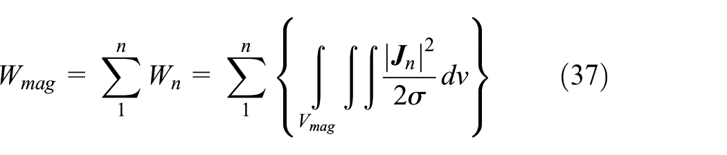
From this, the expression for the nth harmonic time-varying eddy current density Jn can be derived.

The calculation of harmonic eddy current density allows for the determination of eddy current density for each harmonic component. Consequently, it is possible to calculate the overall eddy current losses and harmonic eddy current losses in the permanent magnet using the following equation:
Simulation and discussion
Iron core loss calculation model
Iron core losses and eddy current losses in the permanent magnet are among the most significant losses in MEHC. These two types of losses directly impact the efficiency and performance of the coupler. Therefore, in-depth research of these losses are of paramount importance for the development of MEHC. This effort can help improve the efficiency of the coupler, reduce energy consumption, and extend its lifespan.
Considerable research has been conducted on iron core losses. While the equations mentioned above can provide approximate loss values, they are not always entirely accurate. To address this, Italian scholar Bertotti proposed an iron loss separation calculation model, which can more accurately calculate the iron core losses in the stator when subjected to a sinusoidal changing magnetic field. This model is still widely used. Bertotti’s iron loss separation model includes hysteresis losses, eddy current losses, and abnormal losses, and the calculation equations are as follows:

As mentioned in equation (38), the total iron core losses in the stator and rotor are related to three types of loss coefficients of the silicon steel, the frequency of the changing magnetic field, and the amplitude of the magnetic flux. When the rotational speed is constant, the frequency of the changing magnetic field can be determined. The calculation of the three loss coefficients of the silicon steel can be obtained by fitting the B-H curve of the silicon steel.
Based on the above, it is evident that when using Bertotti’s iron loss separation model to calculate iron core losses, the three loss coefficients of the silicon steel and the changing frequency of the magnetic field have already been determined. Therefore, to calculate stator iron core losses, it is necessary to ascertain the distribution and variations in magnetic flux within the stator. During the motor’s operation, the magnetic flux density at each point on the silicon steel differs and constantly changes. To accurately compute stator iron core losses, you need to calculate the magnetic flux density at each point within the stator and then utilize Bertotti’s iron loss separation model to compute the losses at each point. Ultimately, summing up the losses from each point yields the total stator iron core losses. However, in practical calculations, it’s not feasible to compute losses at every single point. To simplify the computation process while maximizing accuracy, representative points on the stator are chosen for analysis, and the parameters at one point are employed to approximate losses within a specific region.
Stator magnetic flux density analysis
In the electro-hydraulic coupling mode, three points are selected on the stator as shown in Figure 6, which are the stator tooth tip, stator tooth middle, and stator tooth yoke. Within one electrical cycle, the radial and tangential magnetic flux densities at points A, B, and C vary as depicted in Figure 7.

Point selection on the stator of the electric motor.

Magnetic flux density variation at points A, B, and C. The values (a), (b), and (c) in the figure correspond to the magnetic flux densities at points A, B, and C in the diagram above.
It can be observed that the radial magnetic flux density at points A and B is significantly greater than the tangential magnetic flux density, and their variations follow a similar trend. The losses generated at these points are primarily due to hysteresis losses in the alternating magnetic field. At point C, the tangential magnetic flux density is significantly greater than the radial magnetic flux density, resulting in losses primarily due to rotational hysteresis losses. The maximum values of radial and tangential magnetic flux densities at these three points are shown in Table 3.
Amplitude of magnetic flux density.

The stator experiences different magnetization patterns at different positions. While the magnetic flux density curves at these three points closely resemble sinusoidal curves, they exhibit varying degrees of higher-order harmonics. Although the amplitudes of these harmonics are relatively small, they occur at higher frequencies. According to the iron loss calculation model, iron core losses are closely related to the amplitude and frequency of magnetic flux density. The losses introduced by these harmonics should not be overlooked. Frequency decomposition of the radial and tangential magnetic flux densities at points A, B, and C is performed.
From Figure 8, it can be observed that, apart from the fundamental component, the third and fifth harmonics have the most significant impact on losses. In equation (38), only eddy current losses generated by the fundamental magnetic flux density were considered, neglecting the influence of harmonic magnetic flux on losses, which resulted in errors in the calculation. To accurately calculate the stator iron core losses, it is necessary to decompose the magnetic flux density waveforms at various stator points into radial and tangential alternating magnetic fields. Then, calculate the losses generated by the radial magnetic flux fundamental and harmonics, as well as the losses generated by the tangential magnetic flux fundamental and harmonics separately, and add both types of losses together. The final calculated total loss has a smaller error and is closer to the actual loss.
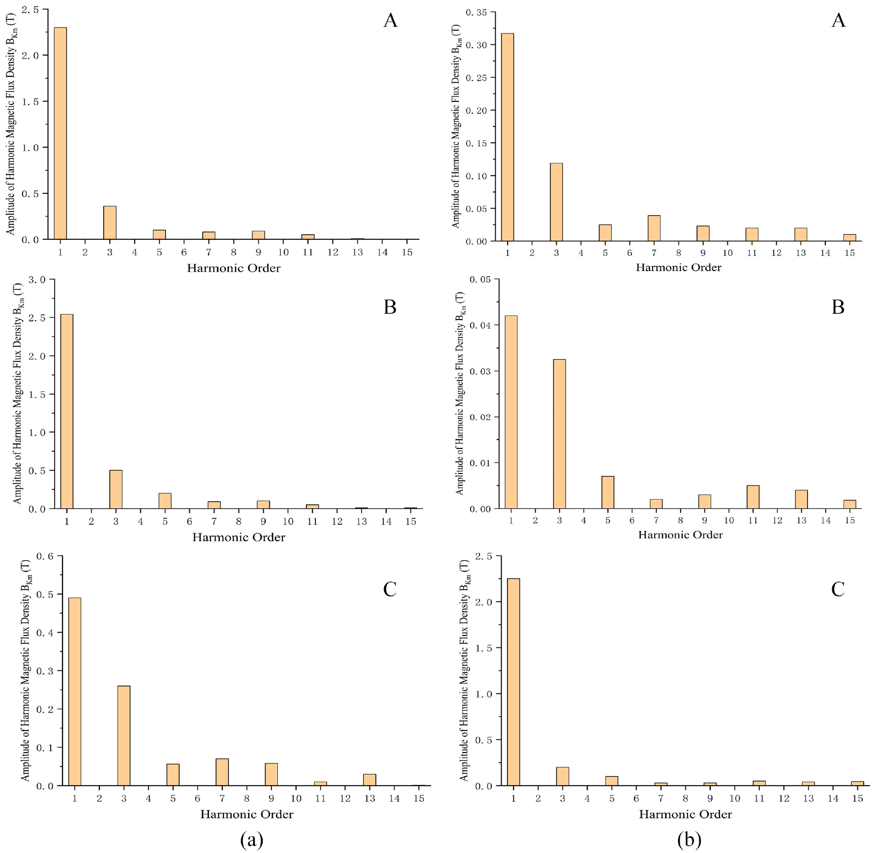
Harmonics of magnetic flux density at points A, B, and C: (a) radial magnetic flux harmonic and (b) tangential magnetic flux harmonic.
Based on the Bertotti iron loss separation model, equation (38) is modified as follows:

Using the finite element electromagnetic software ANSYS Maxwell, simulations were performed to calculate the stator magnetic flux density of the MEHC motor in both the pure electric motor mode and the electro-hydraulic coupling mode under rated load conditions. The results are depicted in Figure 9.

Stator magnetic flux density contour plot under rated load: (a) pure electric motor mode and (b) electro-hydraulic coupling mode.
From Figure 9, it can be observed that the stator tooth region has a higher magnetic flux density compared to the stator yoke region. In both modes, the maximum magnetic flux density occurs at the stator tooth slot, and in the pure electric motor mode, the maximum magnetic flux density is slightly higher than in the electro-hydraulic coupling mode.
Iron core loss finite element calculation
At a rated speed of 3000 rpm and a rated power of 18 kW, three-dimensional finite element simulations were conducted to obtain the stator iron core loss curves for both the pure electric motor mode and the electro-hydraulic coupling mode under rated operating conditions, as shown in Figure 10. The stator loss contour plots are presented in Figure 11.

Motor stator core loss curve.

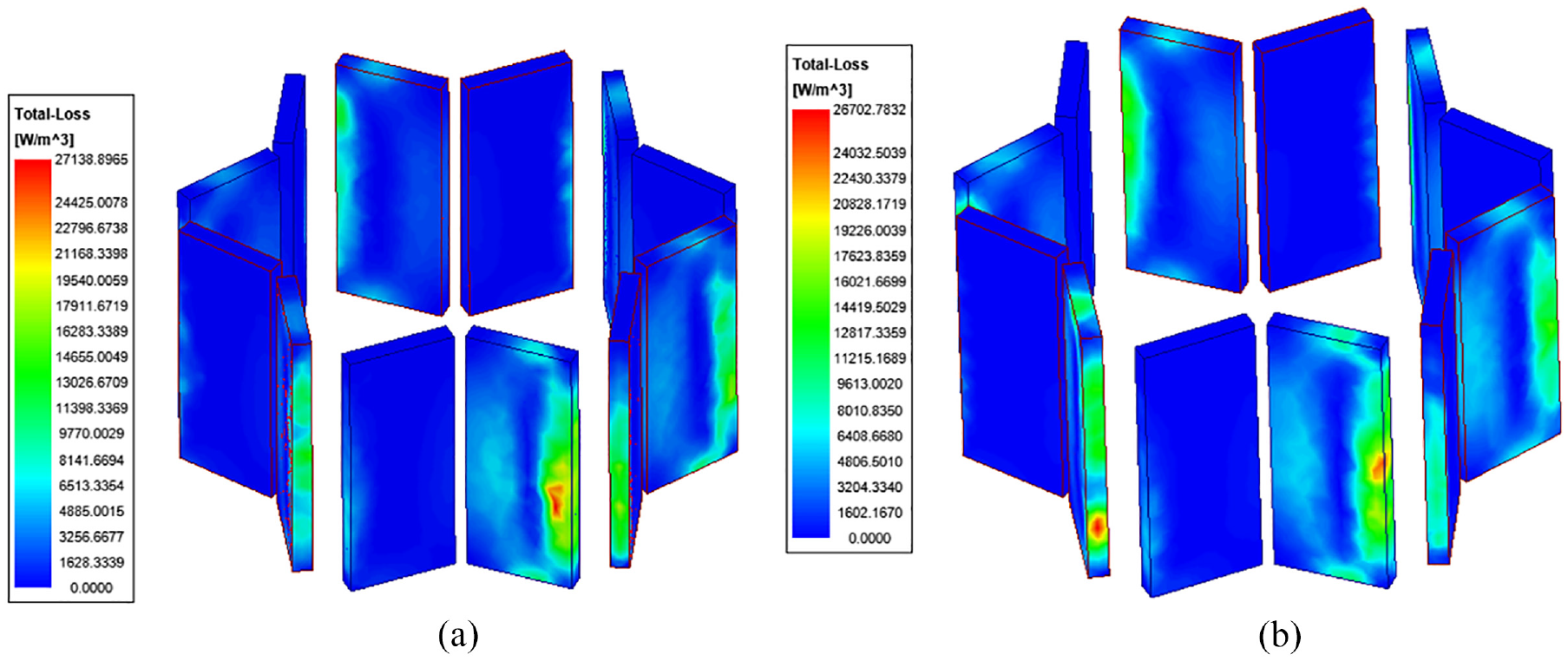
Motor stator core loss contour plot: (a) pure electric motor mode and (b) electro-hydraulic coupling mode.
Figure 10 illustrates that the stator iron core loss in the motor is overall lower in the electro-hydraulic coupling mode compared to the pure electric motor mode. In both modes, the stator core loss stabilizes within the range of 100–110 W. In the pure electric motor mode, the maximum loss is 114.6 W, whereas in the electro-hydraulic coupling mode, the maximum loss is 110.8 W.
Figure 11 shows that the stator core loss distribution in both modes is roughly similar. The losses are more severe in the stator tooth and slot regions, while the stator yoke region experiences lower losses. This is consistent with the earlier analysis of magnetic flux density results, as areas with higher magnetic flux density tend to exhibit greater losses.
At rated operating conditions, three-dimensional finite element simulations were used to calculate the rotor iron core loss curves for both the pure electric motor mode and the electro-hydraulic coupling mode, as shown in Figure 12. The rotor loss contour plots are presented in Figure 13.

Rotor iron core loss curve.

Motor rotor loss contour plot: (a) pure electric motor mode and (b) electro-hydraulic coupling mode.
Figure 12 demonstrates that the rotor iron core loss in the pure electric motor mode exhibits greater fluctuations compared to the electro-hydraulic coupling mode, where the rotor iron core loss is more stable. In both modes, the stator core loss eventually stabilizes within the range of 40–45 W.
Figure 13 reveals that the motor rotor core loss is mainly concentrated on the sides of the rotor, with higher losses occurring near the slot close to the air gap. This is due to the uneven distribution of the magnetic field in the air gap.
Permanent magnet Eddy current loss
When simulating the eddy current loss in the permanent magnet material, the first step is to set the appropriate electrical conductivity for the permanent magnet material in the finite element electromagnetic software ANSYS Maxwell. Then, the eddy current effects are configured for the permanent magnet material. Finally, deep mesh refinement is applied to the permanent magnet material. Eddy current losses are calculated separately for the MEHC pure electric motor mode and the electro-hydraulic coupling mode under rated load conditions, with a calculation duration of two electrical cycles. The eddy current loss curve is shown in Figure 14, and the loss contour plot is displayed in Figure 15.

Permanent magnet eddy current loss curve.
Permanent magnet eddy current loss contour plot: (a) pure electric motor mode and (b) electro-hydraulic coupling mode.
From Figure 14, it can be observed that the permanent magnet eddy current losses stabilize within the range of 35–45 W. In the pure electric motor mode, the maximum eddy current loss in the permanent magnet is 43.87 W, with an average eddy current loss of 38.51 W. In the electro-hydraulic coupling mode, the maximum eddy current loss in the permanent magnet is 42.16 W, with an average eddy current loss of 36.24 W. Overall, in the electro-hydraulic coupling mode, the permanent magnet eddy current losses are lower than those in the pure electric motor mode.
Figure 15 shows that on the side close to the stator, the permanent magnet eddy current losses are higher, and the locations of the losses are roughly the same in both modes.
The advantages of MEHC
The losses of three-phase asynchronous motors are usually greater than those of permanent magnet synchronous motors. This is because the rotor winding of three-phase asynchronous motors is made of conductive materials such as copper and aluminum. In three-phase asynchronous motors, the rotor current is induced, whereas the rotor of permanent magnet synchronous motors contains permanent magnets, and its magnetic field is provided by the permanent magnets, eliminating the need for induced currents. Therefore, three-phase asynchronous motors generate additional currents during operation, leading to more resistance losses and copper losses. In comparison, the losses of permanent magnet synchronous motors are lower. Due to the constant magnetic field generated by the permanent magnets on the rotor, permanent magnet synchronous motors can provide greater torque at both low and rated speeds, while three-phase asynchronous motors require larger currents to generate sufficient torque, resulting in relatively smaller torque at low speeds. I conducted simulation simulations on both with consistent excitation and dimensional parameters.
Because the convergence of three-phase asynchronous motors is relatively slow, they do not start as quickly as permanent magnet synchronous motors. Therefore, the simulation period set for IA-MEHPC is longer. In fact, MEHC performs much better than IA-MEHPC, as shown in the figure
From Figures 16 and 17. The average torque of MEHC is 41.5264, while the average torque of IA-MEHPC is 28.4893. The average losses of MEHC are 40.6325, whereas the average losses of IA-MEHPC are 47.5328. In summary, the torque of MEHC is greater than that of IA-MEHPC, and the losses of MEHC are smaller than those of IA-MEHPC.

Core loss and torque of IA-MEHPC.

Core loss and torque of MEHC.
Electric power efficiency and external characteristics
Control strategy
Currently, there are two commonly used control strategies for calculating the efficiency of permanent magnet synchronous motors. One is based on Maximum Torque Per Ampere (MTPA) control strategy, and the other is based on Loss-Minimizing Control (LMS) strategy. The former aims to maximize torque output under rated current, reduce copper losses, and improve motor efficiency. However, the MTPA strategy does not consider iron losses and cannot achieve the optimal motor efficiency. The latter takes into account various losses during the actual operation of the motor and establishes a relatively accurate motor loss model based on the motor’s equivalent circuit. With the premise of achieving the highest motor efficiency, it controls the current to minimize all losses, ensuring the motor operates at optimal efficiency under all conditions.
This paper uses the Loss-Minimizing Control (LMS) strategy when calculating motor efficiency.
Analysis of electric power efficiency simulation results
Under rated operating conditions, the efficiency simulation results for the MEHC motor system in pure electric motor mode are shown in Figure 18, and the efficiency simulation results in electro-hydraulic coupling mode are shown in Figure 19. In most operating conditions, the motor system efficiency is above 90%, with the maximum efficiency in the electro-hydraulic coupling mode slightly higher than in the pure electric motor mode. In low-speed, high-torque conditions, such as the starting phase of an electric vehicle, the efficiency of the pure electric motor mode is relatively low. In contrast, the electro-hydraulic coupling mode, with the assistance of the hydraulic system, can effectively improve efficiency. Combining the previous analysis of hydraulic system efficiency, using the pure hydraulic mode during the vehicle’s starting phase can effectively avoid the inefficient operating region of the motor. When the speed reaches above 1500 rpm, the electro-hydraulic coupling mode can be used for transition. When the system operates in the high-efficiency region of the motor, the hydraulic system is no longer involved. In the full operating mode, the MEHC operates in a high-efficiency working region, maximizing energy utilization.

Electric power efficiency in pure electric motor mode.

Motor efficiency in electro-hydraulic coupling mode.
External electric power characteristics
In pure electric motor mode, the external electric power characteristics are shown in Figure 20. It can be observed that within the constant torque region, the electric power output torque remains constant, and the output power increases with an increase in speed, while the electric power efficiency also increases with speed. At the critical speed point, both the electric power output and efficiency reach their highest points. Beyond this point, as the speed continues to increase, the electric power output remains constant. The output torque decreases with increasing speed, and efficiency shows a decreasing trend.

External electric power characteristics curve in pure electric motor mode.
Comprehensive characteristics
The greatest advantage of MEHC is the combination of a swash plate axial piston pump/motor and a permanent magnet synchronous motor. Studying its comprehensive power characteristics is essential to gain an in-depth understanding of the system’s performance, features, and behavior. This understanding, in turn, allows for more effective design, control, and maintenance of engineering systems involving this device. Now, let’s connect the previous content and examine the comprehensive power characteristics of the MEHC.
When the swashplate angle is 20°, the load pressure is 40 MPa, and hydraulic power reaches its maximum, the power characteristics of the MEHC are as shown in Figure 21.

Comprehensive characteristics curve of MEHC.
The maximum operating speed of the swash plate axial piston pump/motor in the MEHC is 3000 rpm. When the speed exceeds 3000 rpm, hydraulic power no longer contributes to power output but may provide corresponding power assistance or cease to function completely. As observed in Figure 21, the range from 0 to 3000 rpm falls into the electro-hydraulic coupling zone. In this zone, the system’s torque and efficiency exhibit a decreasing trend because hydraulic power efficiency decreases in this region. While electric power efficiency increases, the efficiency drops slightly due to hydraulic power output being higher than electric power output. When the speed exceeds 3000 rpm, hydraulic power is no longer involved in power output. At this point, the MEHC operates in the electric motor constant power zone, where torque, power, and efficiency undergo a sudden change and gradually stabilize, resulting in higher efficiency.
During the startup phase, MEHC relies on hydraulic power, effectively avoiding the issue of low motor efficiency at startup. As the speed increases, electric power efficiency gradually improves while hydraulic power efficiency decreases. By controlling the swashplate angle to reduce the proportion of hydraulic power output and increase the proportion of electric power output, MEHC can operate within a higher efficiency range. When entering the high-efficiency electric power zone, hydraulic power can be completely disengaged from operation. Through a rational control strategy that adjusts the electro-hydraulic ratio, MEHC can avoid the low-efficiency zones of the swash plate axial piston pump/motor and the permanent magnet synchronous motor, ensuring continuous operation within a higher efficiency range.
Conclusions
To address the issues of traditional multi-source power coupling devices, such as their large volume, loose structure, and low energy conversion efficiency, a multi-source power coupling device called MEHC, based on a permanent magnet synchronous motor and a swash plate axial piston pump/motor, has been proposed. MEHC employs a nested design, where the pistons of the piston pump are embedded within the rotor of the motor, making the overall structure compact and reducing installation complexity.
The paper provides a detailed introduction to the structure and principles of MEHC, as well as its application in vehicles, and compares the losses and torque of MEHC with those of IA-MEHPC. Calculations have been performed for the copper losses, iron core losses, and mechanical losses in the MEHC motor system, and simulations of losses have been carried out in different operating modes. The results indicate that in the pure electric motor mode, iron core losses are higher than those in the electro-hydraulic coupling mode. Efficiency calculations for both modes show that the maximum motor efficiency in the electro-hydraulic coupling mode is higher than that in the pure electric motor mode. In low-speed, high-torque conditions, the electro-hydraulic coupling mode, with the assistance of the hydraulic system, has a significantly larger high-efficiency region than the pure electric motor mode.
This paper computes the external electric power characteristics in pure electric motor mode and the comprehensive characteristics of the MEHC. The calculations are based on a three-dimensional model and represent ideal conditions. The next step involves applying MEHC to a vehicle and conducting simulations under various conditions to assess if its efficiency meets the demands of diverse vehicle operating scenarios.
Footnotes
Handling Editor: Sharmili Pandian
Declaration of conflicting interests
The author(s) declared no potential conflicts of interest with respect to the research, authorship, and/or publication of this article.
Funding
The author(s) disclosed receipt of the following financial support for the research, authorship, and/or publication of this article: The project was supported by the National Natural Science Foundation of China (No. 52075278).